EP1234785B1 - Regallager - Google Patents
Regallager Download PDFInfo
- Publication number
- EP1234785B1 EP1234785B1 EP02100123A EP02100123A EP1234785B1 EP 1234785 B1 EP1234785 B1 EP 1234785B1 EP 02100123 A EP02100123 A EP 02100123A EP 02100123 A EP02100123 A EP 02100123A EP 1234785 B1 EP1234785 B1 EP 1234785B1
- Authority
- EP
- European Patent Office
- Prior art keywords
- aisle
- telescopic
- longitudinal members
- depth
- height
- Prior art date
- Legal status (The legal status is an assumption and is not a legal conclusion. Google has not performed a legal analysis and makes no representation as to the accuracy of the status listed.)
- Expired - Lifetime
Links
- 239000000969 carrier Substances 0.000 description 4
- 229910000831 Steel Inorganic materials 0.000 description 1
- 239000002800 charge carrier Substances 0.000 description 1
- 238000006073 displacement reaction Methods 0.000 description 1
- 239000004033 plastic Substances 0.000 description 1
- 125000006850 spacer group Chemical group 0.000 description 1
- 239000010959 steel Substances 0.000 description 1
- 239000000126 substance Substances 0.000 description 1
- 239000002023 wood Substances 0.000 description 1
Images


Classifications
-
- B—PERFORMING OPERATIONS; TRANSPORTING
- B65—CONVEYING; PACKING; STORING; HANDLING THIN OR FILAMENTARY MATERIAL
- B65G—TRANSPORT OR STORAGE DEVICES, e.g. CONVEYORS FOR LOADING OR TIPPING, SHOP CONVEYOR SYSTEMS OR PNEUMATIC TUBE CONVEYORS
- B65G1/00—Storing articles, individually or in orderly arrangement, in warehouses or magazines
- B65G1/02—Storage devices
- B65G1/04—Storage devices mechanical
- B65G1/0407—Storage devices mechanical using stacker cranes
- B65G1/0435—Storage devices mechanical using stacker cranes with pulling or pushing means on either stacking crane or stacking area
-
- B—PERFORMING OPERATIONS; TRANSPORTING
- B65—CONVEYING; PACKING; STORING; HANDLING THIN OR FILAMENTARY MATERIAL
- B65G—TRANSPORT OR STORAGE DEVICES, e.g. CONVEYORS FOR LOADING OR TIPPING, SHOP CONVEYOR SYSTEMS OR PNEUMATIC TUBE CONVEYORS
- B65G1/00—Storing articles, individually or in orderly arrangement, in warehouses or magazines
- B65G1/02—Storage devices
Definitions
- the invention relates to a rack storage, each with a storage aisle adjacent shelving units, which are divided by vertical supports and horizontal, parallel to the storage lane longitudinal beams in compartments, each compartment has a depth of at least two consecutively arranged parking spaces for each loading unit, and with a movable in the storage lane, provided with a retractable into the compartments lifting device, conveyor.
- the load units are basically formed with loading equipment, such as europallets, chemical pallets or lattice boxes.
- loading equipment such as europallets, chemical pallets or lattice boxes.
- the loading units are usually stored longitudinally, that is, that the three runners of the pallets rest on the side rails (book “Materialflußsysteme” by Reinhardt Jünemann and Thorsten Schmidt, Springer Verlag, Berlin 1999, pages 54 to 57).
- shelf shelves are often created with different shelf spacing, which are each tailored specifically to a cargo unit. However, this means that the loading units can be accommodated only in the specially equipped areas of the camp.
- adjustable tine intervals of the telescopic forks are used, which in each case requires an additional effort in the adjustment of the tines.
- the proximal fork sections of a telescopic fork in the shelf can be achieved in conventional side member systems, as shown in Figure 2, by a vertical offset in the support between the front and the rear parking space. As shown in FIG. 2, this height offset is achieved, for example, by special padding on the longitudinal members 5B; instead, however, the rear side members 58 could be set higher from the outset than the front side members 5A. Because of this height offset, the proximal fork cross sections can be passed over the bearing rail closest to the side member 5A.
- a rack warehouse with a storage lane is already known, adjoined on both sides of rack scaffolding, which are divided by vertical supports and horizontal beams, wherein the side members are parallel to the storage lane.
- the supports and side members divide the rack frame into individual compartments. Each compartment is designed so that it has a depth of at least two consecutively arranged locations for each loading unit.
- a conveyor is movable, which has a retractable into the compartments device.
- US-A-5,927,926 discloses a rack warehouse, in which for the storage of the loading units each two transverse to the longitudinal members extending support rails are provided. These mounting rails extend over the entire depth of the compartment. The distance between the two support rails from each other corresponds approximately to the width and the height of the longitudinal members in about the height of the extendable into the compartments elements of a moving along the storage lane displacement unit.
- the aim of the present invention is to provide a shelf storage of the type mentioned in such a way that a space-optimal and flexible storage of cargo units different Basic dimensions and differently shaped charge carriers in partially or fully automated form is made possible, in particular a multi-place storage (in the direction of the camp gate) and a double deep storage in the individual subjects can be done without any special effort.
- this object is achieved in the aforementioned rack storage, that are arranged on the side rails of each compartment for each of the adjacent parking spaces two mounting rails transversely to the longitudinal members, which extend approximately over the entire depth of the compartment and their distance from each other at least Width and height of which at least equal to the height of the retractable into the compartments part of the lifting device that the lifting device has a telescopically extendable lifting element with at least two sections, that the height of the support rails at least equal to the height of the distal telescope section, that the storage lane nearest Longitudinal members are arranged at a predetermined depth of the storage lane in the subjects, which corresponds to a depth of entry of a proximal telescopic member with a comparatively larger extent in the compartment, and that the support rails of the storage lane n waxed lying longitudinal support via a collar.
- the control panel between these support rails can be moved so that no fork clearances of the pallets or other carriers are required for storage.
- the support rails are arranged with an overhang on the longitudinal members, so that the proximal fork sections of a telescopic fork can enter the shelf without having to drive over a side member.
- the side rail nearest the storage lane is in the compartment depth reset so far that the distance between its front edge to the front edge of the overhanging support rail corresponds approximately to the length of the proximal fork portion.
- this proximal portion of the telescopic fork unhindered retract into the shelf, while the distal portion of the telescopic fork between the support rails reaches the remaining depth of the compartment.
- the height of the support rails is thus determined essentially only by the upper, distal extension of the telescopic fork, whereby they need only have a relatively low height.
- the mounting rails can also be arranged overhanging on the longitudinal members, that each of the storage lane nearest longitudinal beams can be set so far back into the compartment depth that the (stackable) directly on the stacker crane (proximal) thicker section of a telescopic lifting element can enter freely in the tray while the thin outer or distal portion of the lifting element between the support rails reaches the remaining depth of the compartment.
- the mounting rails therefore need only have a relatively low height.
- the degree of fork clearance in the pallets plays no role, an adjustment of the telescopic tines is no longer required.
- the width of the telescopic fork must only be smaller than the distance of the mounting rails.
- a telescopic fork instead of a telescopic fork usually used to use a telescopic table, which ensures sufficient stability for the movement of the load units even with a smaller overall width. In this way can also load units guaranteed. In this way it is also possible to transport loading units with different constructive load carrier design, for example load carriers made of wood, steel, plastic, designs with boards and blocks or designs with and without running-in clearances for storage and retrieval unit telescopic forks.
- FIG. 1 shows the basic structure of a pallet warehouse
- FIG. 2 shows a schematic view of a double-deep arrangement of pallets in a shelf according to conventional technology (longitudinal carrier system)
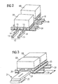
- FIG. 3 shows a double-deep arrangement of pallets in a shelf compartment according to the invention with overhanging mounting rails
- FIG. 4 and FIG. 5 show schematically a side view and a section V of a shelf designed according to the invention.
- FIG. 1 shows the basic structure of a shelf warehouse. It consists of shelving 1, which are each formed on both sides of a storage lane 2 by uprights or supports 3 with cross bars 4 and side rails 5. Each storage tower has a plurality of compartments 10 according to a predetermined rack grid, which is determined by the above-mentioned vertical supports 3 and horizontal crossbar 4 or side member 5. In the individual compartments loading units 6 are arranged on pallets 7, in the example shown in a double-deep arrangement, ie, that in each compartment two loading units are arranged one behind the other.
- FIG 2 shows the arrangement of the loading units 6A and 6B in a conventionally constructed shelf.
- Each loading unit which has a pallet 7 as a loading aid, is mounted on two longitudinal members 5A and 5B.
- the movement of the loading units in the compartment and from the compartment is done by a lifting device of the stacker crane 8, which has a telescopic fork 12.
- the extendable forks of the telescopic fork are shown schematically, namely in each case a proximal tine telescopic section 13 and an outer tine telescopic section 14.
- the lifting device moves into the fork clearance 15 of the pallet 7.
- the inner tine telescopic sections 13 must be lifted over the front side members 5A.
- the rear loading unit 6B is mounted higher on spacer blocks 16 on the rear side rails 5b.
- FIG. 3 shows the arrangement according to the invention for double-deep storage.
- the storage of the loading units 6A and 6B takes place at the same height in each case on two support rails 20 which rest transversely to the longitudinal members 5 on this and hineineruiten in the compartment depth.
- the storage and storage takes place in this case via a lifting device in the form of a telescope-coptic 21 with a proximal telescope section 22 and a distal telescope section 23 (see also Figure 4).
- the distal telescopic section 23 can be moved between the support rails 20 to the rear second parking space, while the proximal telescopic section 22 can be retracted to the front mounting rail 5A.
- This front mounting rail 5A is displaced away from the bearing lane towards the rear in comparison to the conventional embodiment according to FIG. 2, so that the mounting rails 20 project over a length "a" towards the front.
- two side members 5A and 5B are sufficient, since the Loading units do not lie directly on these.
- telescopic forks in a conventional form as shown in FIG. 2 could be used instead of the telescopic table 21.
- Figures 4 and 5 show schematically two views of an inventively designed shelf.
- the compartment has three parking spaces in the longitudinal direction of the warehouse lane and in depth two parking spaces in each case, which in the example shown are each equipped with a pallet loading unit 6.
- the compartment is, as already described with reference to Figure 1, limited by the vertical supports 3 and in height by the horizontal side members 5.
- two mounting rails 20 are arranged inwardly for each parking space, on which the loading units 6 stand.
- Figure 4 shows schematically the storage and retrieval unit 8 with the telescopic table 21 as a lifting device, the telescopic sections 22 and 23 are extended.
- the overhang "a" of the support rail 20 can be seen above the side rail 5 facing the storage lane 2, as a result of which the proximal telescopic section 22 can move in unhindered into the front part of the compartment. Otherwise, the function has already been described with reference to FIG.
Landscapes
- Engineering & Computer Science (AREA)
- Mechanical Engineering (AREA)
- Warehouses Or Storage Devices (AREA)
- Control Of Motors That Do Not Use Commutators (AREA)
- Transition And Organic Metals Composition Catalysts For Addition Polymerization (AREA)
- Bidet-Like Cleaning Device And Other Flush Toilet Accessories (AREA)
- Addition Polymer Or Copolymer, Post-Treatments, Or Chemical Modifications (AREA)
- Devices That Are Associated With Refrigeration Equipment (AREA)
Description
- Die Erfindung betrifft ein Regallager mit jeweils an eine Lagergasse angrenzenden Regalgerüsten, die durch vertikale Stützen und horizontale, parallel zur Lagergasse verlaufende Längsträger in Fächer unterteilt sind, wobei jedes Fach eine Tiefe von mindestens zwei hintereinander angeordneten Stellplätzen für jeweils eine Ladeeinheit aufweist, und mit einer in der Lagergasse bewegbaren, mit einer in die Fächer ausfahrbaren Hubeinrichtung versehenen, Fördereinrichtung.
- In derartigen Regallagern, die gewöhnich als Palettenregale bezeichnet werden, werden die Ladeeinheiten grundsätzlich mit Ladehilfsmitteln gebildet, beispielsweise mit Europaletten, Chemiepaletten oder Gitterboxen. Soweit es sich um Mehrplatzsysteme handelt, werden die Ladeeinheiten üblicherweise längs eingelagert, d.h., daß die drei Kufen der Paletten auf den Längsträgern aufliegen (Buch "Materialflußsysteme" von Reinhardt Jünemann und Thorsten Schmidt, Springer Verlag, Berlin 1999, Seite 54 bis 57). Zur Aufnahme von unterschiedlichen Ladeeinheiten mit unterschiedlichen Ladungsträgern werden dabei häufig Regalstellplätze mit unterschiedlichem Regalraster geschaffen, die jeweils speziell auf eine Ladungseinheit zugeschnitten sind. Das bedeutet aber, daß die Ladeeinheiten jeweils nur in den speziell eingerichteten Bereichen des Lagers untergebracht werden können. Zum Teil werden in Anpassung an die verschiedenen Ladungsträger auch Regalbediengeräte mit verstellbaren Zinkenabständen der Teleskopgabeln verwendet, was jeweils einen zusätzlichen Aufwand bei der Zinkenverstellung erfordert.
- Bei doppelttiefer Lagerung der Ladeeinheiten muß zudem eine Möglichkeit geschaffen werden, daß bei der Bedienung der zweiten Fachtiefe mit dem Regalbediengerät auch die proximalen Gabelabschnitte einer Teleskopgabel in das Regal einfahren können. Dies kann bei herkömmlichen Längsträger-Systemen, wie es in Figur 2 gezeigt ist, durch einen Höhenversatz in der Auflage zwischen dem vorderen und dem hinteren Stellplatz erreicht werden. Wie in Figur 2 gezeigt ist, erreicht man diesen Höhenversatz beispielsweise durch spezielle Aufklotzungen auf den Längsträgern 5B; statt dessen könnten aber die hinteren Längsträger 58 von vornherein höher gelegt werden als die vorderen Längsträger 5A. Aufgrund dieses Höhenversatzes können die proximalen Gabelquerschnitte über den der Lagergasse am nächsten liegenden Längsträger 5A hinweggeführt werden.
- Aus der GB-A-2189779 ist bereits ein Regallager mit einer Lagergasse bekannt, an der beidseitig Regalgerüste angrenzen, die durch vertikale Stützen und horizontale Träger unterteilt sind, wobei die Längsträger parallel zur Lagergasse verlaufen. Dabei unterteilen die Stützen und Längsträger das Regalgerüst in einzelne Fächer. Jedes Fach ist so ausgelegt, dass es über eine Tiefe von mindestens zwei hintereinander angeordneten Stellplätzen für jeweils eine Ladeeinheit verfügt. In der Lagergasse ist eine Fördereinrichtung verfahrbar, welche eine in die Fächer einfahrbare Einrichtung aufweist.
- Weiter offenbart die US-A-5,927,926 ein Regallager, bei dem für die Ablage der Ladeeinheiten jeweils zwei quer zu den Längsträgern verlaufende Tragschienen vorgesehen sind. Diese Tragschienen erstrecken sich über die gesamte Tiefe des Faches. Der Abstand der beiden Tragschienen voneinander entspricht dabei in etwa der Breite und die Höhe der Längsträger in etwa der Höhe der in die Fächer ausfahrbaren Elemente einer sich längs der Lagergasse bewegenden Verschiebeeinheit.
- Ziel der vorliegenden Erfindung ist es, ein Regallager der eingangs genannten Art so auszugestalten, daß eine raumoptimale und flexible Lagerung von Ladungseinheiten verschiedener Grundabmessungen und unterschiedlich gestalteter Ladungsträger in teil- oder auch vollautomatisierter Form ermöglicht wird, wobei insbesondere eine Mehrplatzlagerung (in Richtung der Lagergasse) als auch eine doppelt tiefe Lagerung in den einzelnen Fächern ohne besonderen Aufwand erfolgen kann.
- Erfindungsgemäß wird dieses Ziel bei dem eingangs genannten Regallager dadurch erreicht, daß auf den Längsträgern eines jeden Faches jeweils für jeden der nebeneinanderliegenden Stellplätze zwei Tragschienen quer zu den Längsträgern angeordnet sind, die sich annähernd über die gesamte Tiefe des Faches erstrecken und deren Abstand voneinander zumindest der Breite und deren Höhe zumindest der Höhe des in die Fächer einfahrbaren Teiles der Hubeinrichtung entspricht, daß die Hubeinrichtung ein teleskopartig ausfahrbares Hubelement mit mindestens zwei Abschnitten aufweist, daß die Höhe der Tragschienen mindestens der Höhe des distalen Teleskop-Abschnittes entspricht, daß die der Lagergasse nächstliegenden Längsträger um eine vorgegebene Tiefe von der Lagergasse entfernt in den Fächern angeordnet sind, welcher einer Einfahrtiefe eines proximalen Teleskopgliedes mit vergleichsweise größerem Umfang in dem Fach entspricht, und daß die Tragschienen die der Lagergasse nächstliegenden Längsträger überkragen.
- Durch die erfindungsgemäß vorgesehenen Tragschienen, die sich in Richtung der Fachtiefe erstrecken, können die ausfahrbaren Hubelemente, also beispielsweise Teleskopgabeln, des Regelbediengerätes zwischen diesen Tragschienen bewegt werden, so daß für die Einlagerung keine Gabelfreiräume der Paletten oder sonstigen Ladungsträger benötigt werden.
- Die Tragschienen werden mit einer Überkragung auf den Längsträgern angeordnet, so daß auch die proximalen Gabelabschnitte einer Teleskopgabel in das Regal einfahren können, ohne einen Längsträger überfahren zu müssen. Zu diesem Zweck ist der der Lagergasse nächstliegende Längsträger in die Fachtiefe so weit zurückgesetzt, daß der Abstand seiner Vorderkante zur Vorderkante der überkragenden Tragschiene etwa der Länge des proximalen Gabelabschnittes entspricht. Damit kann dieser proximale Abschnitt der Teleskopgabel ungehindert in das Regalfach einfahren, während der distale Abschnitt der Teleskopgabel zwischen den Tragschienen die restliche Tiefe des Faches erreicht. Die Höhe der Tragschienen wird somit im wesentlichen nur durch den oberen, beim Ausfahren distalen Teil der Teleskopgabel bestimmt, wodurch diese nur eine verhältnismäßig geringe Bauhöhe aufzuweisen brauchen.
- Die Tragschienen können auch so überkragend auf den Längsträgern angeordnet werden, daß jeweils der der Lagergasse nächstliegende Längsträger in die Fachtiefe so weit zurückgesetzt werden kann, daß der unmittelbar am Regalbediengerät liegende (proximale) dickere Abschnitt eines Teleskop-Hubelementes ungehindert in das Fach einfahren kann, während der dünne äußere oder distale Abschnitt des Hubelementes zwischen den Tragschienen die restliche Tiefe des Faches erreicht. Die Tragschienen brauchen deshalb nur eine verhältnismäßig geringe Bauhöhe aufzuweisen.
- Da mit der erfindungsgemäßen Anordnung der Tragschienen das Maß der Gabelfreiräume in den Paletten keine Rolle spielt, ist auch eine Verstellung der Telekopzinken nicht mehr erforderlich. Die Breite der Telekopgabel muß lediglich kleiner sein als der Abstand der Tragschienen. Darüber hinaus ist in einer vorteilhaften Ausgestaltung der Erfindung vorgesehen, anstelle einer üblicherweise verwendeten Teleskopgabel einen Teleskoptisch zu verwenden, der auch bei geringerer Gesamtbreite eine ausreichende Stabilität für die Bewegung der Ladeeinheiten gewährleistet. Auf diese Weise können auch Ladeeinheiten gewährleistet. Auf diese Weise können auch Ladeeinheiten mit unterschiedlicher konstruktiver Ladungsträgergestaltung transportiert werden, zum Beispiel Ladungsträger aus Holz, Stahl, Kunststoff, Ausführungen mit Brettern und Klötzen oder Ausführungen mit und ohne Einfahrfreiräumen für Regalbediengerät-Teleskopgabeln.
- Die Erfindung wird nachfolgend an Ausführungsbeispielen anhand der Zeichnung näher erläutert. Es zeigt
Figur 1 den grundsätzlichen Aufbau eines Palettenlagers,
Figur 2 eine schematische Ansicht einer doppelttiefen Anordnung von Paletten in einem Regalfach nach herkömmlicher Technik (Längsträgersystem),
Figur 3 eine doppelttiefe Anordnung von Paletten in einem Regalfach bei erfindungsgemäßer Gestaltung mit überkragenden Tragschienen,
Figur 4 und Figur 5 ein erfindungsgemäß gestaltetes Regalfach schematisch in Seitenansicht und im Schnitt V. - Figur 1 zeigt den grundsätzlichen Aufbau eines Regallagers. Es besteht aus Regalgerüsten 1, die jeweils zu beiden Seiten einer Lagergasse 2 durch Steher oder Stützen 3 mit Querriegeln 4 und Längsträgern 5 gebildet sind. Jedes Lagergerüst besitzt eine Vielzahl von Fächern 10 nach einem vorgegebenen Regalraster, das durch die erwähnten senkrechten Stützen 3 und waagerechten Querriegel 4 bzw. Längsträger 5 bestimmt wird. In den einzelnen Fächern sind Ladeeinheiten 6 auf Paletten 7 angeordnet, und zwar im gezeichneten Beispiel in doppelttiefer Anordnung, d.h., daß in jedem Fach zwei Ladeeinheiten hintereinander angeordnet sind. Zur Aus- und Einlagerung der Ladeeinheiten dienen Regalbediengeräte 8, die jeweils in jeder Lagergasse vorgesehen sind und an einem Mast 9 vertikal sowie über ein nicht gezeigtes Fahrwerk auch horizontal im Bereich der Lagergasse bewegbar sind, so daß sie jedes Fach erreichen. Die erfindungsgemäße Ausgestaltung der Fächer wird anhand der weiteren Figuren näher gezeigt.
- Figur 2 zeigt die Anordnung der Ladeeinheiten 6A und 6B in einem herkömmlich aufgebauten Regalfach. Dabei ist jede Ladeeinheit, die als Ladehilfsmittel eine Palette 7 besitzt, auf zwei Längsträgern 5A bzw. 5B gelagert. Das bedeutet bei doppelttiefer Lagerung die Anordnung von vier Längsträgern 5 über eine Fachtiefe. Die Bewegung der Ladeeinheiten in das Fach und aus dem Fach geschieht durch eine Hubeinrichtung des Regalbediengerätes 8, welche eine Teleskopgabel 12 aufweist. In Figur 2 sind lediglich die ausfahrbaren Gabelzinken der Teleskopgabel schematisch gezeigt, nämlich jeweils ein proximaler Zinken-Teleskopabschnitt 13 und ein äußerer Zinken-Teleskopabschnitt 14. Mit den distalen Teleskopabschnitten 14 fährt die Hubeinrichtung in die Gabelfreiräume 15 der Palette 7. Für die Aus- bzw. Einlagerung der hinten liegenden Ladeeinheit 6B müssen die inneren Zinken-Teleskopabschnitte 13 über die vorderen Längsträger 5A hinweggehoben werden. Aus diesem Grund wird die hintere Ladeeinheit 6B über Abstandsklötze 16 auf den hinteren Längsträgern 5b höher gelagert.
- Figur 3 zeigt die erfindungsgemäße Anordnung für doppelttiefe Lagerung. Dabei erfolgt die Lagerung der Ladeeinheiten 6A und 6B auf gleicher Höhe jeweils auf zwei Tragschienen 20, die quer zu den Längsträgern 5 auf diesen aufliegen und sich in die Fachtiefe hineinerstrecken. Die Aus- und Einlagerung erfolgt in diesem Fall über eine Hubeinrichtung in Form eines Teles-koptisches 21 mit einem proximalen Teleskopabschnitt 22 und einem distalen Teleskopabschnitt 23 (siehe auch Figur 4). Zur Einlagerung der hinten liegenden Ladeeinheit 6B kann der distale Teleskopabschnitt 23 zwischen den Tragschienen 20 bis zum hinten liegenden zweiten Stellplatz verfahren werden, während der proximale Teleskopabschnitt 22 bis zur vorderen Tragschiene 5A eingefahren werden kann. Diese vordere Tragschiene 5A ist gegenüber der herkömmlichen Ausführungsform gemäß Figur 2 von der Lagergasse weg nach hinten verlagert, so daß die Tragschienen 20 um eine Länge "a" nach vorne überkragen. Im übrigen genügen bei der erfindungsgemäßen Gestaltung für eine Fachtiefe zwei Längsträger 5A und 5B, da die Ladeeinheiten nicht direkt auf diesen liegen. Anstelle des Teleskoptisches 21 könnten natürlich auch Teleskopgabeln in herkömmlicher Form wie in Figur 2 verwendet werden.
- Die Figuren 4 und 5 zeigen schematisch zwei Ansichten eines erfindungsgemäß gestalteten Regalfaches. Das Fach hat in Längsrichtung der Lagergasse drei Stellplätze und in der Tiefe jeweils zwei Stellplätze hintereinander, die in dem gezeigten Beispiel jeweils mit einer Paletten-Ladecinheit 6 bestückt sind. Das Fach wird, wie bereits anhand von Figur 1 beschrieben, durch die senkrechten Stützen 3 und in der Höhe durch die waagerechten Längsträger 5 begrenzt. Auf den Längsträgern sind facheinwärts für jeden Stellplatz zwei Tragschienen 20 angeordnet, auf denen die Ladeeinheiten 6 stehen. Figur 4 zeigt schematisch das Regalbediengerät 8 mit dem Teleskoptisch 21 als Hubvorrichtung, dessen Teleskopabschnitte 22 und 23 ausgefahren sind. Dabei ist insbesondere die Überkragung "a" der Tragschiene 20 über dem der Lagergasse 2 zugewandten Längsträger 5 zu sehen, wodurch der proximale Teleskopabschnitt 22 ungehindert in den vorderen Teil des Faches einfahren kann. Im übrigen wurde die Funktion bereits anhand von Figur 3 beschrieben.
Claims (4)
- Regallager mit jeweils an eine Lagergasse (2) angrenzenden Regalgerüsten (1), die durch vertikale Stützen (3) und horizontale, parallel zur Lagergasse verlaufende Längsträger (5) in Fächer (10) unterteilt sind, wobei jedes Fach (10) eine Tiefe von mindestens zwei hintereinander angeordneten Stellplätzen für jeweils eine Ladeeinheit aufweist, und mit einer in der Lagergasse bewegbaren, mit einer in die Fächer einfahrbaren Hubeinrichtung (12;21) versehenen Fördereinrichtung (8),
dadurch gekennzeichnet ,
daß auf den Längsträgern (5) eines jeden Faches (10) jeweils für jeden der nebeneinander liegenden Stellplätze zwei Tragschienen (20) quer zu den Längsträgern (5) angeordnet sind, die sich annähernd über die gesamte Tiefe des Faches (10) erstrecken und deren Abstand voneinander zumindest der Breite und deren Höhe zumindest der Höhe des in die Fächer (10) ausfahrbaren Teiles der Hubeinrichtung (12;21) entspricht, daß die Hubeinrichtung ein teleskopartig ausfahrbares Hubelement (12;21) mit mindestens zwei Abschnitten (13,14;22,23) aufweist,
daß die Höhe der Tragschienen (20) mindestens der Höhe des distalen Teleskop-Abschnittes (14;23) entspricht,
daß die der Lagergasse (2) nächstliegenden Längsträger (20) um eine vorgegebene Tiefe (a) von der Lagergasse entfernt in den Fächern (10) angeordnet sind, welcher einer Einfahrtiefe eines proximalen Teleskopgliedes (13;22) mit vergleichsweise größerem Umfang in dem Fach entspricht, und
daß die Tragschienen (20) die der Lagergasse nächstliegenden Längsträger (11) überkragen. - Regallager nach Anspruch 1,
dadurch gekennzeichnet , daß die Tragschienen (20) ein Hutprofil aufweisen. - Regallager nach einem der Ansprüche 1 oder 2,
dadurch gekennzeichnet, daß die Fördereinrichtung ein Regalbediengerät (8) ist und eine ausfahrbare Teleskopgabel (12) als Hubeinrichtung aufweist. - Regallager nach einem der Ansprüche 1 bis 3,
dadurch gekennzeichnet , daß die Fördereinrichtung ein Regalbediengerät (8) ist und einen ausfahrbaren Teleskoptisch (21) als Hubeinrichtung aufweist.
Applications Claiming Priority (2)
| Application Number | Priority Date | Filing Date | Title |
|---|---|---|---|
| DE10108944A DE10108944A1 (de) | 2001-02-23 | 2001-02-23 | Regallager |
| DE10108944 | 2001-02-23 |
Publications (2)
| Publication Number | Publication Date |
|---|---|
| EP1234785A1 EP1234785A1 (de) | 2002-08-28 |
| EP1234785B1 true EP1234785B1 (de) | 2006-04-26 |
Family
ID=7675360
Family Applications (1)
| Application Number | Title | Priority Date | Filing Date |
|---|---|---|---|
| EP02100123A Expired - Lifetime EP1234785B1 (de) | 2001-02-23 | 2002-02-11 | Regallager |
Country Status (6)
| Country | Link |
|---|---|
| EP (1) | EP1234785B1 (de) |
| AT (1) | ATE324338T1 (de) |
| DE (2) | DE10108944A1 (de) |
| DK (1) | DK1234785T3 (de) |
| ES (1) | ES2259696T3 (de) |
| PT (1) | PT1234785E (de) |
Cited By (1)
| Publication number | Priority date | Publication date | Assignee | Title |
|---|---|---|---|---|
| WO2025012333A1 (de) * | 2023-07-11 | 2025-01-16 | Kardex Produktion Deutschland Gmbh | Lagergerät mit integriertem arbeitsbereich vor dem zugriffsbereich |
Families Citing this family (7)
| Publication number | Priority date | Publication date | Assignee | Title |
|---|---|---|---|---|
| DE102004056474B4 (de) * | 2004-11-23 | 2009-03-19 | Witron Logistik + Informatik Gmbh | Regallager mit Kommissionierfächern für die automatisierte Kommissionierung von Waren |
| WO2008008818A2 (en) * | 2006-07-11 | 2008-01-17 | J & D Global, Ltd. | Racking system and method of storing palletized items |
| DE102007021068A1 (de) * | 2007-05-04 | 2008-11-06 | Christian Beer | Verfahren und Vorrichtung zum Abgeben und Aufnehmen von Werkstücken auf eine Arbeitsebene |
| EP2325110A1 (de) | 2009-11-18 | 2011-05-25 | Inter IKEA Systems B.V. | Lagersystem zur Lagerung von Gütern auf Einweg-Ladehilfsmitteln und Facheinsatz für ein derartiges Lagersystem |
| DE202009015794U1 (de) | 2009-11-18 | 2011-04-07 | Inter Ikea Systems B.V. | Lagersystem zur Lagerung von Gütern auf Einweg-Ladehilfsmitteln und Facheinsatz für ein derartiges Lagersystem |
| DE102012107176A1 (de) * | 2012-08-06 | 2014-02-06 | Dematic Accounting Services Gmbh | Verfahren zum Bereitstellen von Transporteinheiten aus einem Lager |
| CN104309975A (zh) * | 2014-11-18 | 2015-01-28 | 江苏华鹏智能电气股份有限公司 | 铜排料库 |
Family Cites Families (8)
| Publication number | Priority date | Publication date | Assignee | Title |
|---|---|---|---|---|
| US3633769A (en) * | 1969-06-25 | 1972-01-11 | Vladimir Alexandrovich Dubinsk | Storage premises for storing piece articles |
| DE2030726A1 (de) * | 1970-06-23 | 1972-01-05 | Scheffler, Hellmut, 4811 Heepen | Anlage zur stufenweisen Einlagerung von Lagergütern, insbesondere Langgut |
| US3982638A (en) * | 1974-05-17 | 1976-09-28 | Lamson Frederick W | Device for converting pallets into a storage rack |
| US4570806A (en) * | 1983-05-31 | 1986-02-18 | Allis-Chalmers Corporation | Tote pan and warehouse rack structure therefor |
| JPH0227243B2 (ja) * | 1985-03-27 | 1990-06-15 | Hitachi Ltd | Fuookunoandaakabaasochi |
| JPH0649522B2 (ja) * | 1986-03-24 | 1994-06-29 | 株式会社林原生物化学研究所 | 高層倉庫 |
| DE4301475A1 (en) * | 1992-02-12 | 1993-08-19 | Krupp Stahl Kaltform | Building structure separating rooms one above the other - has cold-rolled profiled girders forming auxiliary ceiling of heat-section open towards main ceiling with flanges converging and then at right angles to it |
| US5927926A (en) * | 1996-10-21 | 1999-07-27 | Itoki Crebio Corporation | Carriage for storage-retrieval system with locking-engaging members |
-
2001
- 2001-02-23 DE DE10108944A patent/DE10108944A1/de not_active Withdrawn
-
2002
- 2002-02-11 PT PT02100123T patent/PT1234785E/pt unknown
- 2002-02-11 AT AT02100123T patent/ATE324338T1/de active
- 2002-02-11 DE DE50206513T patent/DE50206513D1/de not_active Expired - Lifetime
- 2002-02-11 EP EP02100123A patent/EP1234785B1/de not_active Expired - Lifetime
- 2002-02-11 DK DK02100123T patent/DK1234785T3/da active
- 2002-02-11 ES ES02100123T patent/ES2259696T3/es not_active Expired - Lifetime
Cited By (1)
| Publication number | Priority date | Publication date | Assignee | Title |
|---|---|---|---|---|
| WO2025012333A1 (de) * | 2023-07-11 | 2025-01-16 | Kardex Produktion Deutschland Gmbh | Lagergerät mit integriertem arbeitsbereich vor dem zugriffsbereich |
Also Published As
| Publication number | Publication date |
|---|---|
| DE10108944A1 (de) | 2002-09-12 |
| ES2259696T3 (es) | 2006-10-16 |
| DE50206513D1 (de) | 2006-06-01 |
| ATE324338T1 (de) | 2006-05-15 |
| EP1234785A1 (de) | 2002-08-28 |
| DK1234785T3 (da) | 2006-08-14 |
| PT1234785E (pt) | 2006-08-31 |
Similar Documents
| Publication | Publication Date | Title |
|---|---|---|
| EP3286111B1 (de) | Verfahren zum einlagern von stückgütern in ein lagerregal und lagersystem | |
| EP2850968B1 (de) | Stückgutlager | |
| EP1716060B1 (de) | Verfahren und system zum bedienen eines regals in einer kommissionieranlage | |
| AT500229B1 (de) | Rechnergesteuerte transportvorrichtung | |
| EP0268965B1 (de) | Lagereinrichtung | |
| DE2154709C3 (de) | Regalförderzeug | |
| EP2145842B1 (de) | Regallager | |
| DE8905526U1 (de) | Hochregallager zum Ein- und Auslagern von rollenförmigem Gut, insbesondere von Papierrollen | |
| WO2015154116A2 (de) | Regalbediengerät | |
| DE102012220193A1 (de) | Lagergut-Extraktor für ein automatisches Lagersystem | |
| EP2746193B1 (de) | Regalfahrzeug, Regalbediengerät, Lager und entsprechendes Verfahren | |
| DE202018102035U1 (de) | Regalbediengerät und Regallager mit einem solchen Regalbediengarät | |
| WO2019154815A1 (de) | Kommissioniereinrichtung | |
| EP2829502B1 (de) | Lastaufnahmevorrichtung für ein Regalbediengerät | |
| EP1234785A1 (de) | Regallager | |
| DE3644517C2 (de) | ||
| AT509458B1 (de) | Regallager mit regalbediengerät | |
| EP1772399B1 (de) | Regalsystem | |
| DE202004002338U1 (de) | System zum Bedienen eines Regals vorzugsweise in einer Kommissionieranlage | |
| EP1384692A1 (de) | Lagerregal für Waren oder Warengebinde, wie z. B. beladene Paletten | |
| EP0255477B1 (de) | Blechlager | |
| DE2126801A1 (de) | ||
| EP1502880B1 (de) | Lager-und Kommissionieranlage | |
| DE69112064T2 (de) | System zum Handhaben von Materialien. | |
| DE20111541U1 (de) | Container |
Legal Events
| Date | Code | Title | Description |
|---|---|---|---|
| PUAI | Public reference made under article 153(3) epc to a published international application that has entered the european phase |
Free format text: ORIGINAL CODE: 0009012 |
|
| AK | Designated contracting states |
Kind code of ref document: A1 Designated state(s): AT BE CH CY DE DK ES FI FR GB GR IE IT LI LU MC NL PT SE TR |
|
| AX | Request for extension of the european patent |
Free format text: AL;LT;LV;MK;RO;SI |
|
| 17P | Request for examination filed |
Effective date: 20021007 |
|
| AKX | Designation fees paid |
Designated state(s): AT BE CH CY DE DK ES FI FR GB GR IE IT LI LU MC NL PT SE TR |
|
| 17Q | First examination report despatched |
Effective date: 20050131 |
|
| GRAP | Despatch of communication of intention to grant a patent |
Free format text: ORIGINAL CODE: EPIDOSNIGR1 |
|
| RIN1 | Information on inventor provided before grant (corrected) |
Inventor name: SCHWARDT, AXEL Inventor name: LEDERER, JUERGEN |
|
| GRAS | Grant fee paid |
Free format text: ORIGINAL CODE: EPIDOSNIGR3 |
|
| GRAA | (expected) grant |
Free format text: ORIGINAL CODE: 0009210 |
|
| AK | Designated contracting states |
Kind code of ref document: B1 Designated state(s): AT BE CH CY DE DK ES FI FR GB GR IE IT LI LU MC NL PT SE TR |
|
| PG25 | Lapsed in a contracting state [announced via postgrant information from national office to epo] |
Ref country code: IT Free format text: LAPSE BECAUSE OF FAILURE TO SUBMIT A TRANSLATION OF THE DESCRIPTION OR TO PAY THE FEE WITHIN THE PRESCRIBED TIME-LIMIT;WARNING: LAPSES OF ITALIAN PATENTS WITH EFFECTIVE DATE BEFORE 2007 MAY HAVE OCCURRED AT ANY TIME BEFORE 2007. THE CORRECT EFFECTIVE DATE MAY BE DIFFERENT FROM THE ONE RECORDED. Effective date: 20060426 Ref country code: IE Free format text: LAPSE BECAUSE OF FAILURE TO SUBMIT A TRANSLATION OF THE DESCRIPTION OR TO PAY THE FEE WITHIN THE PRESCRIBED TIME-LIMIT Effective date: 20060426 |
|
| REG | Reference to a national code |
Ref country code: GB Ref legal event code: FG4D Free format text: NOT ENGLISH |
|
| REG | Reference to a national code |
Ref country code: CH Ref legal event code: NV Representative=s name: SIEMENS SCHWEIZ AG |
|
| REG | Reference to a national code |
Ref country code: IE Ref legal event code: FG4D Free format text: LANGUAGE OF EP DOCUMENT: GERMAN |
|
| REF | Corresponds to: |
Ref document number: 50206513 Country of ref document: DE Date of ref document: 20060601 Kind code of ref document: P |
|
| GBT | Gb: translation of ep patent filed (gb section 77(6)(a)/1977) |
Effective date: 20060607 |
|
| REG | Reference to a national code |
Ref country code: DK Ref legal event code: T3 |
|
| REG | Reference to a national code |
Ref country code: SE Ref legal event code: TRGR |
|
| REG | Reference to a national code |
Ref country code: PT Ref legal event code: SC4A Effective date: 20060622 |
|
| REG | Reference to a national code |
Ref country code: ES Ref legal event code: FG2A Ref document number: 2259696 Country of ref document: ES Kind code of ref document: T3 |
|
| REG | Reference to a national code |
Ref country code: IE Ref legal event code: FD4D |
|
| ET | Fr: translation filed | ||
| PG25 | Lapsed in a contracting state [announced via postgrant information from national office to epo] |
Ref country code: MC Free format text: LAPSE BECAUSE OF NON-PAYMENT OF DUE FEES Effective date: 20070228 |
|
| PLBE | No opposition filed within time limit |
Free format text: ORIGINAL CODE: 0009261 |
|
| STAA | Information on the status of an ep patent application or granted ep patent |
Free format text: STATUS: NO OPPOSITION FILED WITHIN TIME LIMIT |
|
| 26N | No opposition filed |
Effective date: 20070129 |
|
| PG25 | Lapsed in a contracting state [announced via postgrant information from national office to epo] |
Ref country code: GR Free format text: LAPSE BECAUSE OF FAILURE TO SUBMIT A TRANSLATION OF THE DESCRIPTION OR TO PAY THE FEE WITHIN THE PRESCRIBED TIME-LIMIT Effective date: 20060727 |
|
| REG | Reference to a national code |
Ref country code: CH Ref legal event code: PCAR Free format text: SIEMENS SCHWEIZ AG;INTELLECTUAL PROPERTY FREILAGERSTRASSE 40;8047 ZUERICH (CH) |
|
| PG25 | Lapsed in a contracting state [announced via postgrant information from national office to epo] |
Ref country code: CY Free format text: LAPSE BECAUSE OF FAILURE TO SUBMIT A TRANSLATION OF THE DESCRIPTION OR TO PAY THE FEE WITHIN THE PRESCRIBED TIME-LIMIT Effective date: 20060426 Ref country code: LU Free format text: LAPSE BECAUSE OF NON-PAYMENT OF DUE FEES Effective date: 20070211 |
|
| PG25 | Lapsed in a contracting state [announced via postgrant information from national office to epo] |
Ref country code: TR Free format text: LAPSE BECAUSE OF FAILURE TO SUBMIT A TRANSLATION OF THE DESCRIPTION OR TO PAY THE FEE WITHIN THE PRESCRIBED TIME-LIMIT Effective date: 20060426 |
|
| REG | Reference to a national code |
Ref country code: CH Ref legal event code: NV Representative=s name: ALDO ROEMPLER PATENTANWALT Ref country code: CH Ref legal event code: PUE Owner name: DEMATIC GMBH Free format text: SIEMENS AKTIENGESELLSCHAFT#WITTELSBACHERPLATZ 2#80333 MUENCHEN (DE) -TRANSFER TO- DEMATIC GMBH#CARL-LEGIEN-STRASSE 15#63073 OFFENBACH (DE) |
|
| REG | Reference to a national code |
Ref country code: GB Ref legal event code: 732E Free format text: REGISTERED BETWEEN 20110120 AND 20110126 |
|
| REG | Reference to a national code |
Ref country code: NL Ref legal event code: SD Effective date: 20110211 |
|
| REG | Reference to a national code |
Ref country code: FR Ref legal event code: TP |
|
| REG | Reference to a national code |
Ref country code: ES Ref legal event code: PC2A Owner name: DEMATIC GMBH Effective date: 20110418 |
|
| REG | Reference to a national code |
Ref country code: PT Ref legal event code: PC4A Owner name: DEMATIC GMBH, DE Effective date: 20110606 |
|
| REG | Reference to a national code |
Ref country code: FR Ref legal event code: PLFP Year of fee payment: 15 |
|
| REG | Reference to a national code |
Ref country code: FR Ref legal event code: PLFP Year of fee payment: 16 |
|
| REG | Reference to a national code |
Ref country code: FR Ref legal event code: PLFP Year of fee payment: 17 |
|
| PGFP | Annual fee paid to national office [announced via postgrant information from national office to epo] |
Ref country code: NL Payment date: 20190218 Year of fee payment: 18 |
|
| PGFP | Annual fee paid to national office [announced via postgrant information from national office to epo] |
Ref country code: FI Payment date: 20190122 Year of fee payment: 18 Ref country code: CH Payment date: 20190218 Year of fee payment: 18 Ref country code: FI Payment date: 20190219 Year of fee payment: 18 |
|
| PGFP | Annual fee paid to national office [announced via postgrant information from national office to epo] |
Ref country code: SE Payment date: 20190218 Year of fee payment: 18 Ref country code: FR Payment date: 20190219 Year of fee payment: 18 Ref country code: BE Payment date: 20190218 Year of fee payment: 18 Ref country code: DK Payment date: 20190220 Year of fee payment: 18 Ref country code: AT Payment date: 20190219 Year of fee payment: 18 |
|
| PGFP | Annual fee paid to national office [announced via postgrant information from national office to epo] |
Ref country code: PT Payment date: 20190205 Year of fee payment: 18 |
|
| REG | Reference to a national code |
Ref country code: FI Ref legal event code: MAE |
|
| REG | Reference to a national code |
Ref country code: DK Ref legal event code: EBP Effective date: 20200229 |
|
| REG | Reference to a national code |
Ref country code: SE Ref legal event code: EUG |
|
| REG | Reference to a national code |
Ref country code: CH Ref legal event code: PL |
|
| REG | Reference to a national code |
Ref country code: NL Ref legal event code: MM Effective date: 20200301 |
|
| REG | Reference to a national code |
Ref country code: AT Ref legal event code: MM01 Ref document number: 324338 Country of ref document: AT Kind code of ref document: T Effective date: 20200211 |
|
| GBPC | Gb: european patent ceased through non-payment of renewal fee |
Effective date: 20200211 |
|
| REG | Reference to a national code |
Ref country code: BE Ref legal event code: MM Effective date: 20200229 |
|
| PG25 | Lapsed in a contracting state [announced via postgrant information from national office to epo] |
Ref country code: PT Free format text: LAPSE BECAUSE OF NON-PAYMENT OF DUE FEES Effective date: 20200911 Ref country code: FI Free format text: LAPSE BECAUSE OF NON-PAYMENT OF DUE FEES Effective date: 20200211 Ref country code: SE Free format text: LAPSE BECAUSE OF NON-PAYMENT OF DUE FEES Effective date: 20200212 |
|
| PG25 | Lapsed in a contracting state [announced via postgrant information from national office to epo] |
Ref country code: AT Free format text: LAPSE BECAUSE OF NON-PAYMENT OF DUE FEES Effective date: 20200211 Ref country code: LI Free format text: LAPSE BECAUSE OF NON-PAYMENT OF DUE FEES Effective date: 20200229 Ref country code: CH Free format text: LAPSE BECAUSE OF NON-PAYMENT OF DUE FEES Effective date: 20200229 |
|
| PG25 | Lapsed in a contracting state [announced via postgrant information from national office to epo] |
Ref country code: NL Free format text: LAPSE BECAUSE OF NON-PAYMENT OF DUE FEES Effective date: 20200301 |
|
| PG25 | Lapsed in a contracting state [announced via postgrant information from national office to epo] |
Ref country code: GB Free format text: LAPSE BECAUSE OF NON-PAYMENT OF DUE FEES Effective date: 20200211 Ref country code: DK Free format text: LAPSE BECAUSE OF NON-PAYMENT OF DUE FEES Effective date: 20200229 Ref country code: FR Free format text: LAPSE BECAUSE OF NON-PAYMENT OF DUE FEES Effective date: 20200229 |
|
| PG25 | Lapsed in a contracting state [announced via postgrant information from national office to epo] |
Ref country code: BE Free format text: LAPSE BECAUSE OF NON-PAYMENT OF DUE FEES Effective date: 20200229 |
|
| PGFP | Annual fee paid to national office [announced via postgrant information from national office to epo] |
Ref country code: DE Payment date: 20210217 Year of fee payment: 20 |
|
| PGFP | Annual fee paid to national office [announced via postgrant information from national office to epo] |
Ref country code: ES Payment date: 20210421 Year of fee payment: 20 |
|
| PG25 | Lapsed in a contracting state [announced via postgrant information from national office to epo] |
Ref country code: IT Free format text: LAPSE BECAUSE OF NON-PAYMENT OF DUE FEES Effective date: 20200211 |
|
| REG | Reference to a national code |
Ref country code: DE Ref legal event code: R071 Ref document number: 50206513 Country of ref document: DE |
|
| REG | Reference to a national code |
Ref country code: ES Ref legal event code: FD2A Effective date: 20220526 |
|
| PG25 | Lapsed in a contracting state [announced via postgrant information from national office to epo] |
Ref country code: ES Free format text: LAPSE BECAUSE OF EXPIRATION OF PROTECTION Effective date: 20220212 |