EP1233900B1 - Bauteil für ein kraftfahrzeug - Google Patents
Bauteil für ein kraftfahrzeug Download PDFInfo
- Publication number
- EP1233900B1 EP1233900B1 EP01978326A EP01978326A EP1233900B1 EP 1233900 B1 EP1233900 B1 EP 1233900B1 EP 01978326 A EP01978326 A EP 01978326A EP 01978326 A EP01978326 A EP 01978326A EP 1233900 B1 EP1233900 B1 EP 1233900B1
- Authority
- EP
- European Patent Office
- Prior art keywords
- plastic
- component
- basic body
- duct
- half shells
- Prior art date
- Legal status (The legal status is an assumption and is not a legal conclusion. Google has not performed a legal analysis and makes no representation as to the accuracy of the status listed.)
- Expired - Lifetime
Links
Images









Classifications
-
- B—PERFORMING OPERATIONS; TRANSPORTING
- B62—LAND VEHICLES FOR TRAVELLING OTHERWISE THAN ON RAILS
- B62D—MOTOR VEHICLES; TRAILERS
- B62D25/00—Superstructure or monocoque structure sub-units; Parts or details thereof not otherwise provided for
- B62D25/08—Front or rear portions
- B62D25/14—Dashboards as superstructure sub-units
- B62D25/145—Dashboards as superstructure sub-units having a crossbeam incorporated therein
-
- B—PERFORMING OPERATIONS; TRANSPORTING
- B60—VEHICLES IN GENERAL
- B60H—ARRANGEMENTS OF HEATING, COOLING, VENTILATING OR OTHER AIR-TREATING DEVICES SPECIALLY ADAPTED FOR PASSENGER OR GOODS SPACES OF VEHICLES
- B60H1/00—Heating, cooling or ventilating devices
- B60H1/00507—Details, e.g. mounting arrangements, desaeration devices
- B60H1/00557—Details of ducts or cables
- B60H1/00564—Details of ducts or cables of air ducts
-
- B—PERFORMING OPERATIONS; TRANSPORTING
- B60—VEHICLES IN GENERAL
- B60H—ARRANGEMENTS OF HEATING, COOLING, VENTILATING OR OTHER AIR-TREATING DEVICES SPECIALLY ADAPTED FOR PASSENGER OR GOODS SPACES OF VEHICLES
- B60H1/00—Heating, cooling or ventilating devices
- B60H1/24—Ventilating devices where the heating or cooling is irrelevant
- B60H1/241—Ventilating devices where the heating or cooling is irrelevant characterised by the location of ventilation devices in the vehicle
- B60H1/242—Ventilating devices where the heating or cooling is irrelevant characterised by the location of ventilation devices in the vehicle located in the front area
-
- B—PERFORMING OPERATIONS; TRANSPORTING
- B62—LAND VEHICLES FOR TRAVELLING OTHERWISE THAN ON RAILS
- B62D—MOTOR VEHICLES; TRAILERS
- B62D25/00—Superstructure or monocoque structure sub-units; Parts or details thereof not otherwise provided for
- B62D25/08—Front or rear portions
- B62D25/14—Dashboards as superstructure sub-units
- B62D25/142—Dashboards as superstructure sub-units having ventilation channels incorporated therein
-
- B—PERFORMING OPERATIONS; TRANSPORTING
- B62—LAND VEHICLES FOR TRAVELLING OTHERWISE THAN ON RAILS
- B62D—MOTOR VEHICLES; TRAILERS
- B62D29/00—Superstructures, understructures, or sub-units thereof, characterised by the material thereof
- B62D29/04—Superstructures, understructures, or sub-units thereof, characterised by the material thereof predominantly of synthetic material
Definitions
- the invention relates to a component for a motor vehicle, in particular a Cross member for the cockpit area, according to the preamble of claim 1 and a manufacturing method and uses of this component.
- the pipes can be in principle for air guidance, for example, from a center in the vehicle arranged air conditioning to lateral vents (see for example DE 197 53 877), whereby this is not used until today, because of the Metal pipes can easily deposit unwanted condensation.
- the one preferably made of metal existing shell-shaped body has, in the interior Reinforcing ribs are arranged.
- the reinforcing ribs consist of injected plastic and are discrete with the metal body Connected joints by placing the plastic in the metal part arranged apertures interspersed and over the surfaces of the apertures extends.
- the metal body is U-shaped and the Enforce reinforcing ribs for high rigidity and Strength the interior of the body.
- This known hybrid component has an advantageous low weight with sufficient strength at the same time, Stiffness and resilience. An air duct is with this as a carrier usable lightweight component not possible.
- From DE-U 200 08 201 is a cross member in hybrid construction with a shell-like body of which is injected by an Plastic ribbing is stiffened, known.
- the plastic ribs are shaped such that serving as an air duct plastic pipe can be inserted positively.
- introduction of a channel is complicated, because the channel is made separately and in one step must be inserted.
- the thus adapted in shape ribs lose stability.
- the older non-prepublished EP-A-1 075 972 describes a component which in particular a cross member for placing between A-pillars of a Motor vehicle, with a substantially tubular body, in the at least one channel is provided, wherein the main body inside with Plastic lined is used to form plastic Channel walls.
- the main body is lined on the inside with molded-on plastic, see above that the channel walls are formed of plastic.
- additional Air duct components such as blowing parts, air hoses o. The like.
- the wall thickness of the usually metal existing Body can be reduced, thereby saving weight can.
- On the channel walls, which consist of plastic on the inside, can no or at least less condensation of in the conditioned air contained moisture. The same applies to the condensation on the outside of the channels.
- In the channel could also other media, such as Wiping water for the headlights or the windshield, cooling water, Oil, compressed air or the like can be performed or stored.
- the channel for the protected laying of cables, fuel line, oil line, Compressed air lines or the like or for storage of Serve objects are not more necessary.
- the wall thickness of the usually metal existing Body can be reduced, thereby saving weight can.
- On the channel walls, which consist of plastic on the inside can no or at least less condensation of in the conditioned air contained moisture. The same applies to the condensation on the outside of the channels.
- the component according to the invention has the further advantage that compared to the known components in which a combination of metal and Plastic is used, now according to the invention, a cheaper Plastic can be used, because in the component according to the invention the plastic does not need to perform any essential strength function.
- a cheaper Plastic is mostly for insulation, e.g. thermal or Soundproofing.
- the strength results from the combination of Body and plastic, thus achieving a synegetic effect becomes.
- thinner sheet metal and cheaper plastic can be used.
- the main body openings which with the Plastic are interspersed and being attached to the main body brackets, Connection points or housing parts of a heating or air conditioning o.
- Elements of the plastic are integrally formed. Due to the Breakthroughs, the body is firmly connected to the plastic, Similar to a component in hybrid construction, so that the Component according to the invention also an advantageously lower weight having.
- channel walls of the formed by the body But closed channels, these openings are through closed the plastic.
- connection points or for example Housing parts of an air conditioner are molded with, so that in one single process step an instrument panel carrier with cross member can be obtained, which is easy, a variety of connection points and has holders and possibly also already housing parts and in the one air duct, for example for the guidance of conditioned air, is included.
- the plastic is in an injection molding process recoverable.
- Such a plastic introduced can be made relatively strong be and also hold functions.
- the plastic is allowed to have a lower strength, it can out a foam material, for example a polyurethane foam or a particle foam.
- a plastic that is very light and yet has high strength consists of foam particles interconnected by a binder.
- foam particles interconnected by a binder.
- Such a composite plastic for example, in the trade under the Brand name "Xeratec" available.
- the component preferably forms one between the A-pillars of the Vehicle to be arranged cross member to which the instrument panel and other components, such as steering column, airbag or the like. be connected can.
- the variety of parts in the production of the motor vehicle reduced because the component according to the invention, for example as Instrument panel support all mounts and air ducts and a Part of the air conditioner housing may contain. This allows assembly time and labor can be saved and an advantageous Pre-testability of the component is made possible.
- integrally molded Be provided plastic ribs.
- connection points such as the connections to A-pillars of a Vehicles must be very stable and should therefore be made of metal.
- Such connection elements are in one embodiment of the invention therefore to the body before the introduction of the plastic Welding, clinching or other joining methods attachable. You could for example, be further stabilized via plastic ribs.
- the tubular base body is made Two half-shells are formed, over the introduced plastic connected to each other. Tube-like crossbeams with their many Connection points for steering column, airbag, etc., are more cost-effective two half-shells can be produced.
- the Half shells can not be pre-connected with each other but can be considered as Half shells are inserted into the tool. In the tool can they are then optionally mechanically interconnected, for example, by caulking.
- the Half shells in addition or even exclusively on the introduced Plastic are interconnected, for example, in the manner of Rivets, so that the plastic forms rivets, among other things. To do this of course, corresponding openings in the half-shells be provided, which are filled with the plastic.
- vents in the longitudinal direction at a distance from each other are arranged and advantageously in at least one of Half shells seen in the longitudinal direction between each two Vents provided a filling possibility.
- the adjacent edges connection points for other components form.
- the component according to the invention is used as a cross member in a Motor vehicle, wherein the channel is an air duct and / or a Cable duct is used.
- the component could be considered under one Windshield arranged cross member in a motor vehicle, wherein the channel an air duct for guiding the windshield to De-icing or heating a wiper blade tray and / or the Side windows to be supplied Defrostluft is used.
- a Another possibility of using the component according to the invention is as Cross member in a front end region of the motor vehicle, wherein the channel a conduit is or a container for a medium, such as wiper water for the headlights or the windshield, cooling water, oil, compressed air or the like, or a channel for a protected installation of Gasoline lines, oil lines, compressed air lines or the like forms.
- the component according to the invention could also be used as a rear-end or Heckabschlußmodul find use.
- the channel of the component can in an embodiment of the invention in the Process step of plastic insertion through a tool core be formed, which is particularly advantageous if the plastic injected under pressure.
- casting for example, a blow core, a filled molding tube, Gases, granules, a Ausschmelzkern or a lost core used become.
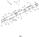
- An illustrated in the drawing inventive component 10 is in the illustrated embodiment designed as a dashboard and is referred to below as a cross member.
- the cross member 10 is in a vehicle in a manner not shown between the A-pillars of Vehicle arranged and fixable to this in a suitable manner. With the arrow 12, the direction of travel is indicated.
- the cross member 10 has a preferably made of metal Base 14, which is formed substantially tubular.
- brackets such as a steering column mount 16 and 17 and connecting elements 18, 20, 21 for a passenger airbag tethered.
- These brackets and connection elements consist in also preferably made of metal and are attached to the body 14 suitably connected, for example, welded.
- Reinforcement and better stiffening can reinforcing ribs Plastic, as indicated for example by the reference numeral 19, be provided.
- the brackets and attachment elements can also be surrounded by the plastic, whereby the rigidity is increased, a Rattling is avoided and an edge protection is given.
- the main body 14 is lined on the inside with plastic 22 and forms a channel 24 with internal walls 25 for guiding media, for example air.
- the plastic can in the main body 14 in a Injection molding process be introduced. Alternatively and depending on the type of the plastic, this can also be foamed, poured or in be introduced in a similar manner, as already explained in detail above. In the following description, for example, only the injection in the Injection molding mentioned, but not limited to.
- the main body 14 has a plurality of openings on, which are interspersed by the plastic, as for example in the Reference numerals 26 and 28 are shown. At 26 and 28 the plastic forms virtually a rivet, so that the plastic firmly with the main body 14th connected is.
- the main body 14 has a further plurality of openings, which are also interspersed by the plastic, but on the Outside of the cross member 14 form a holder, like this
- a holder like this
- 30 or 32 is indicated.
- the brackets 30 and Fig. 32 is shown schematically as simple eyelets and hooks. The various forms for the brackets are conceivable.
- the cross member approximately centrally has a larger opening 34, to which a plastic shell 36 connects.
- This plastic shell 36 may form part of an air conditioning housing, not shown, from the conditioned air into the channel 24 can be introduced.
- the air becomes through the channel 24 to provided in the cross member outlet openings 40, 42, 44, 46 out.
- At the outlet openings close each Air outlet 50, 52, 54, 56, which preferably also from the Plastic exist.
- All plastic parts such as channel inner walls 25, rivets 26, 28, brackets 30, 32, housing part 36, air outlet spigot 50, 52, 54, 56, Reinforcing ribs 19 are injected in a single injection molding process.
- the base body is first formed and with the provided corresponding openings. Then they are made of metal existing brackets welded, riveted, toxtoiled, screwed or the like attached. Thereafter, the body is in a corresponding Injection mold inserted and all plastic parts in one Injection molding molded onto the body.
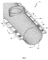
- the Channel-forming base body 114 of the component 110 according to the invention formed in two parts (Fig. 4) and consists of first and second half-shell 116 and 118, which are shown in Fig. 5 individually.
- the half shells 116 and 118 each have angled longitudinal edges 120 and 122 or 124 and 126, in the formation of the tubular base body 14, as in Fig. 6 represented, lie against each other.
- the longitudinal edges 120, 122, 124 and 126 are shaped such that when abutting (Fig. 6) vent openings 128th remain free, as shown in Fig. 8 in detail. The function of this Vents 128 will be described later in the description of the Production method explained in more detail.
- Air outlet stubs 151 and 153 can be provided in one or both half-shells 116, 118.
- the tubular base 114 is the same as in the first embodiment lined on the inside with a plastic 130, wherein the plastic in injected an injection molding process.
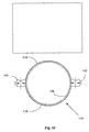
- the plastic 130 covers it not only the insides of the body 114 with its half shells 116th and 118, but also penetrates the vents 128 and encompasses outermost edges 132 and 134 of the angled edges 120, 122, 124 and 126, as shown for example in FIG. 7 and in the cross section in FIG. 9 can be seen. This shows a first possibility, as the two half shells 116 and 118 over the injected plastic 130th can be connected to each other.
- a second way to connect the two half-shells 116 and 118 is also shown in FIG. 7 and in the cross section in FIG.
- a Kunststoffniet 140 in and around the fürbmasteren 136 and 138 injected so that on this plastic rivet 140 is given a further connection option.
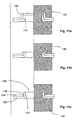
- the can Openings 136 and 138 may be designed differently in detail, such as this is shown in detail on individual examples in FIGS. 11a, b and c is.
- the openings 136 and 138 passages 142 and 144 through which, where appropriate, the exact assembly of the Half shells 116 and 118 can be simplified.
- these passages can also over a Stamp 146, for example, after inserting the half-shells in a Injection mold are bent so that at the same time a mechanical connection between the two half shells 116 and 118th given is.
- the punch and the associated die after flanging the passage 144 retracted and the outer shape of the thereafter injected plastic rivet 140 determine.
- the shape of the half-shell 116 and 118 may differ in detail be formed, as for example the representations in Figs to 19 show.
- the channel formed by the main body 114 not only round but also polygonal, such as in FIG. 19 shown.
- the half-shells 116 and 118 Before the Splashing the plastic 130, the half-shells 116 and 118th pivoted together to form the main body 114, in which then the Plastic 130 is injected.
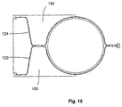
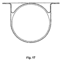
- the longitudinal edges 120, 122, 124 and 126 of the Half shells 116 and 118 may be formed in various ways, as in FIGS. 13 to 18. In particular, they can be designed in this way be that the longitudinal edges connecting points for other components, such as For example, steering column, airbag or the like form. if the Longitudinal edges are formed very bulging, such as in Fig. 15th at the longitudinal edges 120 and 124, these edges 120 and 124 are reinforced by plastic ribs 150, wherein the Plastic ribs 150 preferably sprayed in the same injection molding process become.
- the reinforcing ribs 150 may also have openings 152 have, as shown in Fig. 16, so that parallel to the through Main body formed channel, for example, cables can be performed.
- FIG. 18 shows an embodiment in which the longitudinal edges 120, 122, 124 and 126 are not angled, but in the direction of the circumference of the base body 114 are formed, so that the half-shells 116 and 118 are virtually nestable.
- the connection of the half-shells 116 and 118 may turn over not shown rivet, such as they are shown in Figs. 11 and 12, be realized.
- This second embodiment 110 of the component according to the invention is in essentially the same as the previously described Embodiment with respect to FIGS. 1 to 3.
- the Half shells 116 and 118 of the body 114 shaped, for example in a deep-drawing process and the appropriate brackets attached, for example, welded.
- the half shells 116 and 118 placed in the injection mold and injected the plastic 130, whereby then the main body 140 lined on the inside with plastic and at the same time the two half-shells 116 and 118, as above described, be interconnected.
- the half-shells Have Anspritzö réelleen 160 the center in the circumferential direction at least one preferably two half-shells 116, 118 are arranged and in the longitudinal direction between each two vents 128th are arranged. Then, as in FIG. 20, flow lines 162 may be used indicated, the injected plastic in an advantageous manner, starting from the Anspritzö réelleen 160, flow relatively unpressurized, whereby by the Vents 128 the air displaced in the injection molding process can escape. As a result, a process-safe injection molding process allows, in which the plastic improves flow in all areas can.
Landscapes
- Engineering & Computer Science (AREA)
- Mechanical Engineering (AREA)
- Combustion & Propulsion (AREA)
- Transportation (AREA)
- Chemical & Material Sciences (AREA)
- Physics & Mathematics (AREA)
- Thermal Sciences (AREA)
- Structural Engineering (AREA)
- Architecture (AREA)
- Body Structure For Vehicles (AREA)
- Injection Moulding Of Plastics Or The Like (AREA)
- Air-Conditioning For Vehicles (AREA)
- Seal Device For Vehicle (AREA)
- Vehicle Body Suspensions (AREA)
- Instrument Panels (AREA)
Description
- Formen des Grundkörpers mit den entsprechenden Öffnungen und/oder Durchbrechungen
- Anbringen der aus Material des Grundkörpers bestehenen Halterungen an den Grundkörper
- Einlegen des/der Grundkörper(s) in ein Werkzeug
- Anformen, beispielsweise Anspritzen, sämtlicher Kunststoffteile und Kunststoffauskleidungen an den Grundkörper in einem einzigen Verfahrensschritt.
- Fig. 1
- eine perspektivische Ansicht eines erfindungsgemäßen Bauteils als Instrumententafelträger ;
- Fig. 2
- eine Ansicht wie Fig. 1 aus einer anderen Perspektive;
- Fig. 3
- eine Ansicht des Bauteils aus Fig. 1 von der Seite;
- Fig. 4
- eine Ansicht einer Ausführungsform des erfindungsgemäßen Bauteils mit zwei Halbschalen;
- Fig. 5
- die beiden Halbschalen des Bauteils aus Fig. 4 in Explosionsdarstellung;
- Fig. 6
- die beiden Halbschalen des Bauteils aus Fig. 4 zusammengesetzt dargestellt;
- Fig. 7
- eine Detailansicht des Bauteils aus Fig. 4;
- Fig. 8
- eine Ansicht der Ränder der beiden Halbschalen aus der Ansicht VIII aus Fig. 6;
- Fig. 9 und 10
- Querschnitte entlang der Linien IX-IX und X-X aus Fig. 7;
- Fig. 11a bis c
- sowie
- Fig. 12a bis b
- Querschnitte verschiedener Ausführungsformen der Verbindungen der Halbschalen;
- Fig. 13 bis 18
- Ansichten verschiedener Ausführungen des Bauteils mit verschiedenen Rändern und ggf. zusätzlichen Kanälen;
- Fig. 19
- ein Bauteil mit unrundem Querschnitt;
- Fig. 20
- Darstellung des Kunststoffflusses im Spritzgußprozeß.
Claims (23)
- Bauteil, insbesondere Querträger zum Anordnen zwischen A-Säulen eines Kraftfahrzeuges, mit einem im wesentlichen rohrartigen Grundkörper (14, 114), in dem wenigstens ein Kanal (24) vorgesehen ist, dadurch gekennzeichnet, daß der Grundkörper (14, 114) innen mit angeformtem Kunststoff (22, 130) ausgekleidet ist zur Bildung von aus Kunststoff bestehenden Kanalwänden (25).
- Bauteil nach einem der vorhergehenden Ansprüche, dadurch gekennzeichnet, daß der Grundkörper (14) Durchbrechungen aufweist, die mit dem Kunststoff (22) durchsetzt sind und daß an den Grundkörper Halterungen (30, 32), Anbindungspunkte oder Gehäuseteile (36) einer Heizungs- oder Klimaanlage o. dgl. Elemente aus dem Kunststoff einstückig angeformt sind.
- Bauteil nach Anspruch 2, dadurch gekennzeichnet, daß der Grundkörper (14) und/oder die Halterungen und/oder Anbindungspunkte (21) über einstückig angeformte Kunststoffrippen (19) aussteifbar sind.
- Bauteil nach einem der vorhergehenden Ansprüche, dadurch gekennzeichnet, daß der Kunststoff in einem Spritzgußverfahren einbringbar ist.
- Bauteil nach einem der vorhergehenden Ansprüche 1 bis 3, dadurch gekennzeichnet, daß der Kunststoff aus einem Schaummaterial, beispielsweise einem Polyurethanschaum oder einem Partikelschaum, besteht.
- Bauteil nach einem der vorhergehenden Ansprüche, dadurch gekennzeichnet, daß der Kunststoff aus über ein Bindemittel miteinander verbundenen Schaumpartikeln besteht.
- Bauteil nach Anspruch 3, dadurch gekennzeichnet, daß an den Grundkörper (14) vor dem Anformen des Kunststoffs weitere Anbindungspunkte (18, 20, 21) oder Halterungen (16, 17) durch Schweißen, Clinchen oder andere Fügeverfahren anbindbar sind und die beispielsweise über die Kunststoffrippen (19) aussteifbar sind.
- Bauteil nach einem der vorhergehenden Ansprüche, dadurch gekennzeichnet, daß der rohrartige Grundkörper (114) aus zwei Halbschalen (116, 118) gebildet ist, die über den angeformten Kunststoff (130) miteinander verbunden sind.
- Bauteil nach Anspruch 8, dadurch gekennzeichnet, daß die Halbschalen (116, 118) über den Kunststoff (130) nach Art von Nieten (140) zusammengehalten sind.
- Bauteil nach Anspruch 9, dadurch gekennzeichnet, daß die Halbschalen (116,118) zusätzlich mechanisch verbunden sind.
- Bauteil nach einem der vorhergehenden Ansprüche 8 bis 10, dadurch gekennzeichnet, daß zwischen aneinanderliegenden Rändern (120 und 124, 122 und 126) der beiden Halbschalen (116, 118) Entlüftungsöffungen (128) vorgesehen sind, die im Herstellprozeß zumindest teilweise mit Kunststoff (130) ausfüllbar sind.
- Bauteil nach Anspruch 11, dadurch gekennzeichnet, daß die Entlüftungsöffnungen (128) in Längsrichtung des Grundkörpers mit Abstand zueinander angeordnet sind.
- Bauteil nach Anspruch 12, dadurch gekennzeichnet, daß in wenigstens einer der Halbschalen (116, 118) in Längsrichtung gesehen jeweils zwischen zwei Entlüftungsöffnungen (128) eine Befüllmöglichkeit (160) vorgesehen ist.
- Bauteil nach einem der vorhergehenden Ansprüche 8 bis 13, dadurch gekennzeichnet, daß die aneinanderliegenden Ränder (120 und 124, 122 und 126) der beiden Halbschalen (116, 118) Anbindungspunkte für weitere Komponenten bilden.
- Verwendung eines Bauteils nach einem der vorhergehenden Ansprüche 1 bis 14 als Instrumententafelträger in einem Kraftfahrzeug, wobei der Kanal ein Luftführungskanal und/oder ein Kabelkanal ist.
- Verwendung eines Bauteils nach einem der vorhergehenden Ansprüche 1 bis 14 als unter einer Windschutzscheibe angeordneter Querträger in einem Kraftfahrzeug, wobei der Kanal ein Luftführungskanal zur Führung der der Windschutzscheibe und/oder den Seitenscheiben zuzuführenden Defrostluft ist und/oder zur Beheizung einer Wischblattablage.
- Verfahren zur Herstellung eines Bauteils (10, 110) nach Anspruch 2, bei dem zunächst der Grundkörper (14, 114) geformt und mit den entsprechenden Öffnungen und/oder Durchbrechungen versehen wird, dann die aus Metall bestehenen Halterungen (16, 17, 21) an den Grundkörper (14, 114) angebracht werden und danach der Grundkörper (14, 114) in ein Werkzeug eingelegt wird und sämtliche Kunststoffteile und Kunststoffauskleidungen in einem einzigen Verfahrensschritt an den Grundkörper (14, 114) angeformt, beispielsweise angespritzt, werden.
- Verfahren nach Anspruch 17 und wobei der Rohrartige Grundkörper (114) aus zwei Halbschalen (116, 118) gebildet ist, dadurch gekennzeichnet, daß vor dem Verfahrensschritt des Kunststoffeinbringens die Halbschalen (116, 118) in dem Werkzeug durch beispielsweise Verstemmen miteinander verbunden werden.
- Verfahren nach einem der vorhergehenden Ansprüche 17 oder 18, dadurch gekennzeichnet, daß der Kanal in dem Verfahrensschritt des Kunststoffeinbringens durch einen Werkzeugkern gebildet wird.
- Verfahren nach einem der vorhergehenden Ansprüche 17 oder 18, dadurch gekennzeichnet, daß der Kanal in dem Verfahrensschritt des Kunststoffeinbringens durch einen Blaskem, einen gefüllten Formschlauch, durch Gase oder Granulate gebildet wird.
- Verfahren nach einem der vorhergehenden Ansprüche 17 oder 18, dadurch gekennzeichnet, daß der Kanal in dem Verfahrensschritt des Kunststoffeinbringens durch einen Ausschmelzkern gebildet wird.
- Verfahren nach einem der vorhergehenden Ansprüche 17 oder 18, dadurch gekennzeichnet, daß der Kanal in dem Verfahrensschritt des Kunststoffeinbringens durch einen verlorenen Kern gebildet wird.
- Verfahren nach Anspruch 17 und wobei der Rohrartige Grundkörper (114) aus zwei Halbschalen (116, 118) gebildet ist, dadurch gekennzeichnet, daß die den Grundkörper bildenden Halbschalen vor dem Zusammenfügen mit Kunststoff ausgekleidet werden.
Applications Claiming Priority (5)
| Application Number | Priority Date | Filing Date | Title |
|---|---|---|---|
| DE10044292 | 2000-09-07 | ||
| DE10044292 | 2000-09-07 | ||
| DE10064522 | 2000-12-22 | ||
| DE10064522A DE10064522A1 (de) | 2000-09-07 | 2000-12-22 | Bauteil für ein Kraftfahrzeug |
| PCT/EP2001/010024 WO2002020334A1 (de) | 2000-09-07 | 2001-08-30 | Bauteil für ein kraftfahrzeug |
Publications (2)
| Publication Number | Publication Date |
|---|---|
| EP1233900A1 EP1233900A1 (de) | 2002-08-28 |
| EP1233900B1 true EP1233900B1 (de) | 2004-07-21 |
Family
ID=26006963
Family Applications (1)
| Application Number | Title | Priority Date | Filing Date |
|---|---|---|---|
| EP01978326A Expired - Lifetime EP1233900B1 (de) | 2000-09-07 | 2001-08-30 | Bauteil für ein kraftfahrzeug |
Country Status (7)
| Country | Link |
|---|---|
| US (1) | US6921127B2 (de) |
| EP (1) | EP1233900B1 (de) |
| JP (1) | JP2004508243A (de) |
| AT (1) | ATE271488T1 (de) |
| AU (1) | AU2002210476A1 (de) |
| ES (1) | ES2225612T3 (de) |
| WO (1) | WO2002020334A1 (de) |
Cited By (1)
| Publication number | Priority date | Publication date | Assignee | Title |
|---|---|---|---|---|
| DE102009010345A1 (de) * | 2009-02-25 | 2010-08-26 | Hbpo Gmbh | Frontendmodul für Fahrzeuge |
Families Citing this family (39)
| Publication number | Priority date | Publication date | Assignee | Title |
|---|---|---|---|---|
| JP4239594B2 (ja) * | 2002-04-10 | 2009-03-18 | 株式会社デンソー | 車両用空調ダクト構造 |
| DE10220025A1 (de) * | 2002-05-04 | 2003-11-20 | Behr Gmbh & Co | Querträger |
| DE60310339T2 (de) * | 2002-11-01 | 2007-05-10 | Calsonic Kansei Corp. | Querträger und Herstellungsverfahren |
| DE10254348B4 (de) * | 2002-11-21 | 2005-02-24 | Daimlerchrysler Ag | Baugruppe für einen Cockpit-Bereich |
| US7128360B2 (en) * | 2002-12-10 | 2006-10-31 | Delphi Technologies, Inc. | Structural hybrid attachment system and method |
| US6988764B2 (en) * | 2003-01-28 | 2006-01-24 | Calsonic Kansei Corporation | Cross car beam for vehicle |
| EP1520676A1 (de) * | 2003-10-02 | 2005-04-06 | Behr GmbH & Co. KG | Verfahren und Vorrichtung zur Herstellung eines Hybridbauteils, insbesondere für einen Querträger eines Fahrzeugs |
| BRPI0415175A (pt) * | 2003-10-08 | 2006-11-28 | Behr Gmbh & Co Kg | componente estrutural para um dispositivo para climatização de um compartimento interno de veìculo e dispositivo para climatização de um compartimento interno de veìculo |
| ATE452813T1 (de) * | 2003-10-08 | 2010-01-15 | Behr Gmbh & Co Kg | Bauteil, verwendung eines bauteils sowie verfahren zur herstellung eines bauteils, insbesondere eines querträgers für ein fahrzeug |
| EP1673272B1 (de) * | 2003-10-08 | 2010-06-30 | Behr GmbH & Co. KG | Verfahren und vorrichtung zur herstellung eines bauteils, insbesondere eines hybridbaudteils für einen quertr ger eines fahrzeugs sowie bauteil und verwendung eines bauteils |
| US20070006986A1 (en) * | 2003-10-08 | 2007-01-11 | Martin Derleth | Component, especially a hybid carrier for a vehicle, and method for the production of said type of component, and use of said type of component |
| ATE399663T1 (de) * | 2003-10-08 | 2008-07-15 | Behr Gmbh & Co Kg | Bauteil, insbesondere hybridbauteil für einen querträger eines fahrzeugs und verwendung eines bauteils |
| WO2005037632A1 (de) * | 2003-10-14 | 2005-04-28 | Behr Gmbh & Co. Kg | Verbundbauteil, insbesondere querträger |
| DE502004010600D1 (de) * | 2003-10-17 | 2010-02-11 | Behr Gmbh & Co Kg | Bauteil für ein kraftfahrzeug |
| US20070245758A1 (en) * | 2004-03-02 | 2007-10-25 | Georg Binder | Component for a Motor Vehicle Structure |
| DE102004013384A1 (de) * | 2004-03-17 | 2005-10-06 | Behr Gmbh & Co. Kg | Querträger oder Strukturbauteil für ein Kraftfahrzeug |
| ES2300756T3 (es) * | 2004-03-26 | 2008-06-16 | Autotech Engineering, A.I.E. | Traviesa de soporte para tablero de instrumentos. |
| FR2872091B1 (fr) * | 2004-06-25 | 2008-03-07 | Faurecia Interieur Ind Snc | Traverse de planche de bord |
| FR2872742B1 (fr) * | 2004-07-07 | 2008-12-05 | Valeo Climatisation Sa | Poutre de renfort d'un habitacle organisee pour la reception d'un module de distribution selective d'air d'une installation de chauffage, de ventilation et/ou de climatisation |
| DE102005004605B4 (de) * | 2005-02-01 | 2009-03-05 | Lisa Dräxlmaier GmbH | Querträgermodul für ein Kraftfahrzeug |
| FR2881708B1 (fr) * | 2005-02-04 | 2007-05-04 | Valeo Systemes Thermiques | Poutre structurelle pour habitacle de vehicule, logeant des organes aerauliques de distribution selective d'air |
| DE202005003080U1 (de) * | 2005-02-25 | 2006-07-06 | Magna Automotive Services Gmbh | Modulträger |
| JP2006306345A (ja) * | 2005-05-02 | 2006-11-09 | Toyota Motor Corp | 中空構造部材の内包材配設構造 |
| US7585017B2 (en) | 2005-05-10 | 2009-09-08 | Noble Advanced Technologies, Inc. | One-piece, tubular member with an integrated welded flange and associated method for producing |
| FR2886889B1 (fr) * | 2005-06-14 | 2007-08-17 | Renault Sas | Conduit de distribution d'air dans l'habitacle d'un vehicule automobile |
| EP2001647B1 (de) * | 2006-03-21 | 2013-05-08 | Inteva Products | Herstellungsverfahren fuer ein integriertes strukturelement für ein fahrzeug |
| DE102006037303A1 (de) * | 2006-08-08 | 2008-02-14 | Behr Gmbh & Co. Kg | Bauteil für einen Träger eines Fahrzeugs |
| US8366166B2 (en) * | 2008-02-07 | 2013-02-05 | Toyota Motor Engineering & Manufacturing North America, Inc. | Duct anti-rotation attachment flange |
| DE102008039652A1 (de) * | 2008-08-26 | 2010-03-11 | Lanxess Deutschland Gmbh | Querträgermodul für ein Kraftfahrzeug |
| DE102009026297B4 (de) * | 2009-07-31 | 2013-08-08 | Thyssenkrupp Steel Europe Ag | Cockpitquerträger mit variablem Lenksäulenneigungswinkel |
| US20120273539A1 (en) * | 2011-04-28 | 2012-11-01 | GM Global Technology Operations LLC | Support structure and method of manufacturing the same |
| DE102012204892A1 (de) | 2012-03-27 | 2013-10-02 | Mekra Lang Gmbh & Co. Kg | Temperierbares Gehäuse zur Aufnahme einer elektronischen Einrichtung und Fahrzeug mit diesem Gehäuse |
| FR2991650B1 (fr) * | 2012-06-07 | 2014-06-20 | Peugeot Citroen Automobiles Sa | Traverse pour planche de bord de vehicule pourvue d'une entretoise de renfort dorsal en composite fibre |
| DE102012213813B4 (de) * | 2012-08-03 | 2021-07-01 | Mekra Lang Gmbh & Co. Kg | Außenkameravorrichtung für Fahrzeuge sowie Fahrzeug mit einer solchen Außenkameravorrichtung |
| US8925993B2 (en) | 2012-10-26 | 2015-01-06 | Denso International America, Inc. | Mounting feature to cross car beam |
| PT106837A (pt) * | 2013-03-14 | 2014-09-15 | Sodecia Ct Tecnológico S A | Travessa para veículos motorizados com a função de evitar a redução do espaço interior do habitáculo em caso de choque lateral |
| US10882378B2 (en) * | 2017-08-18 | 2021-01-05 | Zhejiang CFMOTO Power Co., Ltd. | ATV air heat exchanger with mounting structure and linkage |
| US11407454B2 (en) * | 2019-05-20 | 2022-08-09 | Faurecia Interior Systems, Inc. | Composite vehicle crossmember |
| FR3135955A1 (fr) | 2022-05-30 | 2023-12-01 | Faurecia Interieur Industrie | Traverse de véhicule, véhicule comprenant une telle traverse, et ensemble de deux traverses |
Citations (1)
| Publication number | Priority date | Publication date | Assignee | Title |
|---|---|---|---|---|
| EP1075972A2 (de) * | 1999-08-13 | 2001-02-14 | Bayerische Motoren Werke Aktiengesellschaft | Luftleitsystem für ein Kraftfahrzeug |
Family Cites Families (26)
| Publication number | Priority date | Publication date | Assignee | Title |
|---|---|---|---|---|
| US2664373A (en) * | 1950-10-25 | 1953-12-29 | Dow Chemical Co | Method of lining rigid pipe with elastic thermoplastics |
| US3372462A (en) * | 1965-10-11 | 1968-03-12 | Upjohn Co | Method of making plastic lined metal pipe |
| US3934064A (en) * | 1971-11-24 | 1976-01-20 | E. I. Du Pont De Nemours And Company | Composite structures of knitted glass fabric and thermoplastic polyfluoroethylene resin sheet |
| CH553597A (de) * | 1972-05-24 | 1974-09-13 | Arx Paul Von | Verfahren zum anbringen einer beschichtung auf der innenwand eines rohres. |
| US4347277A (en) * | 1978-11-03 | 1982-08-31 | General Signal Corporation | Corrosion resistant coated articles which include an intermediate coating layer of a thermosetting polymer and non-siliceous filler |
| US4272971A (en) * | 1979-02-26 | 1981-06-16 | Rockwell International Corporation | Reinforced tubular structure |
| JPS5611179U (de) * | 1979-07-05 | 1981-01-30 | ||
| US4329879A (en) * | 1980-07-14 | 1982-05-18 | Fischer & Porter Co. | Insulating liner for electromagnetic flowmeter tube |
| US4403933A (en) * | 1982-04-14 | 1983-09-13 | Fischer & Porter Company | Apparatus for injection-molding a liner onto a metal spool |
| US4592886A (en) * | 1982-04-28 | 1986-06-03 | Fischer & Porter | Technique for stabilizing injection molded flowmeter liner |
| DE3220023C2 (de) * | 1982-05-27 | 1993-05-27 | Cellofoam Deutschland Gmbh, 7950 Biberach | Schalldämpfender Strömungskanal und Verfahren zu seiner Herstellung |
| DE3839855A1 (de) | 1988-11-25 | 1990-05-31 | Bayer Ag | Leichtbauteil |
| JPH02125484U (de) * | 1989-03-27 | 1990-10-16 | ||
| DE4232847A1 (de) | 1992-09-30 | 1994-03-31 | Audi Ag | Armaturenbrett für ein Kraftfahrzeug |
| US5364159A (en) * | 1993-06-15 | 1994-11-15 | Davidson Textron Inc. | Structural instrument panel carrier assembly |
| US5566721A (en) * | 1995-07-20 | 1996-10-22 | Dana Corporation | Driveshaft tube having sound deadening coating |
| FR2756801B1 (fr) | 1996-12-10 | 1999-02-05 | Reydel Sa | Tableau de bord pour vehicule, notamment destine a des vehicules automobiles |
| DE19720902A1 (de) | 1997-05-17 | 1998-11-19 | Mannesmann Vdo Ag | Baugruppe für einen Cockpit-Bereich eines Fahrzeuges |
| DE19812288C1 (de) * | 1998-03-20 | 1999-05-27 | Moeller Plast Gmbh | Hohlprofil mit Innenversteifung und Verfahren zur Herstellung dieses Hohlprofils |
| JP3772549B2 (ja) * | 1998-09-11 | 2006-05-10 | 日産自動車株式会社 | 電気自動車のバッテリ冷却構造 |
| FR2789043B1 (fr) * | 1999-01-29 | 2001-06-08 | Valeo Climatisation | Poutre transversale de support d'une planche de bord de vehicule automobile, a conduit d'air integre |
| US6186885B1 (en) | 1999-02-18 | 2001-02-13 | Ford Motor Company | Integrated HVAC system for an automotive vehicle |
| DE29916470U1 (de) | 1999-09-18 | 1999-12-09 | Benteler Ag, 33104 Paderborn | Instrumententräger |
| DE10005718A1 (de) | 2000-02-09 | 2001-08-16 | Volkswagen Ag | Zugleich als Strömungsmittelleitug dienender Hohlträger |
| DE20008201U1 (de) | 2000-05-08 | 2000-07-27 | Benteler Ag, 33104 Paderborn | Instrumententafelträger |
| US6592069B1 (en) * | 2000-06-06 | 2003-07-15 | Dan Cobble | Mini-beam yarn supply apparatus and method |
-
2001
- 2001-08-30 AT AT01978326T patent/ATE271488T1/de not_active IP Right Cessation
- 2001-08-30 WO PCT/EP2001/010024 patent/WO2002020334A1/de not_active Ceased
- 2001-08-30 AU AU2002210476A patent/AU2002210476A1/en not_active Abandoned
- 2001-08-30 US US10/111,570 patent/US6921127B2/en not_active Expired - Fee Related
- 2001-08-30 JP JP2002524974A patent/JP2004508243A/ja active Pending
- 2001-08-30 ES ES01978326T patent/ES2225612T3/es not_active Expired - Lifetime
- 2001-08-30 EP EP01978326A patent/EP1233900B1/de not_active Expired - Lifetime
Patent Citations (1)
| Publication number | Priority date | Publication date | Assignee | Title |
|---|---|---|---|---|
| EP1075972A2 (de) * | 1999-08-13 | 2001-02-14 | Bayerische Motoren Werke Aktiengesellschaft | Luftleitsystem für ein Kraftfahrzeug |
Cited By (1)
| Publication number | Priority date | Publication date | Assignee | Title |
|---|---|---|---|---|
| DE102009010345A1 (de) * | 2009-02-25 | 2010-08-26 | Hbpo Gmbh | Frontendmodul für Fahrzeuge |
Also Published As
| Publication number | Publication date |
|---|---|
| AU2002210476A1 (en) | 2002-03-22 |
| ATE271488T1 (de) | 2004-08-15 |
| JP2004508243A (ja) | 2004-03-18 |
| EP1233900A1 (de) | 2002-08-28 |
| WO2002020334A1 (de) | 2002-03-14 |
| US20020153750A1 (en) | 2002-10-24 |
| ES2225612T3 (es) | 2005-03-16 |
| US6921127B2 (en) | 2005-07-26 |
Similar Documents
| Publication | Publication Date | Title |
|---|---|---|
| WO2002020334A1 (de) | Bauteil für ein kraftfahrzeug | |
| DE10064522A1 (de) | Bauteil für ein Kraftfahrzeug | |
| DE102007006722C5 (de) | Träger für eine Karosserie eines Kraftwagens | |
| EP1682401B1 (de) | Bauteil, verwendung eines bauteils sowie verfahren zur herstellung eines bauteils, insbesondere eines querträgers für ein fahrzeug | |
| EP1136345B1 (de) | Querträger in Hybridbauweise | |
| EP1254043B1 (de) | Bauteil für ein kraftfahrzeug | |
| EP2064108B1 (de) | Tragrohr einer instrumententafel eines kraftfahrzeugs | |
| EP0836983B1 (de) | Vorderwandrahmen für eine selbsttragende Karosserie eines Personenkraftwagens und Verfahren zu seiner Herstellung | |
| DE10220025A1 (de) | Querträger | |
| EP2782787B1 (de) | Mittelkonsole für fahrzeuge sowie verfahren zu deren herstellung | |
| DE102005004605A1 (de) | Querträgermodul für ein Kraftfahrzeug | |
| DE19505935A1 (de) | Struktur zur Absorption von Aufprallenergie durch ein nichtmetallisches Innenraummaterial eines Kraftfahrzeuges | |
| DE102005061506B4 (de) | Strukturteil für ein Fahrzeug | |
| DE29916466U1 (de) | Instrumententräger | |
| EP1762468B1 (de) | Querträger für ein Kraftfahrzeug | |
| DE202010018117U1 (de) | Instrumententafelstruktur eines Kraftfahrzeugs und Kraftfahrzeug, das eine derartige Struktur umfasst | |
| DE602005004699T2 (de) | Instrumententräger | |
| WO2020147963A1 (de) | Achsträger für kraftfahrzeuge und herstellung desselben | |
| EP1500578B1 (de) | Modulträger-Teil und Verfahren zu seiner Pressformung | |
| EP2379362A2 (de) | Kraftstoffbehälter mit einbauten und verfahren zu dessen fertigung | |
| DE10251762A1 (de) | Grundträger für eine Fahrzeugstruktur sowie Verfahren zur Herstellung eines Grundträgers | |
| DE602005005561T2 (de) | Träger im Fahrzeuginnenraum für eine Luftversorgungseinrichtungeinheit einer Klima-Anlage. | |
| DE19933533A1 (de) | Luftleitsystem für ein Kraftfahrzeug | |
| EP1851103B1 (de) | Modulträger für ein kraftfahrzeug | |
| DE102005025082A1 (de) | Querträger mit integrierter Luftführung für ein Kraftfahrzeug |
Legal Events
| Date | Code | Title | Description |
|---|---|---|---|
| PUAI | Public reference made under article 153(3) epc to a published international application that has entered the european phase |
Free format text: ORIGINAL CODE: 0009012 |
|
| AK | Designated contracting states |
Kind code of ref document: A1 Designated state(s): AT BE CH CY DE DK ES FI FR GB GR IE IT LI LU MC NL PT SE TR |
|
| AX | Request for extension of the european patent |
Free format text: AL;LT;LV;MK;RO;SI |
|
| 17P | Request for examination filed |
Effective date: 20020916 |
|
| 17Q | First examination report despatched |
Effective date: 20030123 |
|
| RIN1 | Information on inventor provided before grant (corrected) |
Inventor name: WOLF, WALTER Inventor name: REDDIG, THOMAS Inventor name: FEITH, THOMAS Inventor name: NEUSS, SABINE |
|
| GRAP | Despatch of communication of intention to grant a patent |
Free format text: ORIGINAL CODE: EPIDOSNIGR1 |
|
| GRAS | Grant fee paid |
Free format text: ORIGINAL CODE: EPIDOSNIGR3 |
|
| GRAA | (expected) grant |
Free format text: ORIGINAL CODE: 0009210 |
|
| AK | Designated contracting states |
Kind code of ref document: B1 Designated state(s): AT BE CH CY DE DK ES FI FR GB GR IE IT LI LU MC NL PT SE TR |
|
| PG25 | Lapsed in a contracting state [announced via postgrant information from national office to epo] |
Ref country code: CY Free format text: LAPSE BECAUSE OF FAILURE TO SUBMIT A TRANSLATION OF THE DESCRIPTION OR TO PAY THE FEE WITHIN THE PRESCRIBED TIME-LIMIT Effective date: 20040721 Ref country code: NL Free format text: LAPSE BECAUSE OF FAILURE TO SUBMIT A TRANSLATION OF THE DESCRIPTION OR TO PAY THE FEE WITHIN THE PRESCRIBED TIME-LIMIT Effective date: 20040721 Ref country code: IE Free format text: LAPSE BECAUSE OF FAILURE TO SUBMIT A TRANSLATION OF THE DESCRIPTION OR TO PAY THE FEE WITHIN THE PRESCRIBED TIME-LIMIT Effective date: 20040721 Ref country code: TR Free format text: LAPSE BECAUSE OF FAILURE TO SUBMIT A TRANSLATION OF THE DESCRIPTION OR TO PAY THE FEE WITHIN THE PRESCRIBED TIME-LIMIT Effective date: 20040721 Ref country code: FI Free format text: LAPSE BECAUSE OF FAILURE TO SUBMIT A TRANSLATION OF THE DESCRIPTION OR TO PAY THE FEE WITHIN THE PRESCRIBED TIME-LIMIT Effective date: 20040721 |
|
| REG | Reference to a national code |
Ref country code: GB Ref legal event code: FG4D Free format text: NOT ENGLISH |
|
| REG | Reference to a national code |
Ref country code: CH Ref legal event code: EP |
|
| REG | Reference to a national code |
Ref country code: IE Ref legal event code: FG4D Free format text: GERMAN |
|
| REF | Corresponds to: |
Ref document number: 50102920 Country of ref document: DE Date of ref document: 20040826 Kind code of ref document: P |
|
| PG25 | Lapsed in a contracting state [announced via postgrant information from national office to epo] |
Ref country code: AT Free format text: LAPSE BECAUSE OF NON-PAYMENT OF DUE FEES Effective date: 20040830 Ref country code: LU Free format text: LAPSE BECAUSE OF NON-PAYMENT OF DUE FEES Effective date: 20040830 |
|
| PG25 | Lapsed in a contracting state [announced via postgrant information from national office to epo] |
Ref country code: MC Free format text: LAPSE BECAUSE OF NON-PAYMENT OF DUE FEES Effective date: 20040831 Ref country code: BE Free format text: LAPSE BECAUSE OF NON-PAYMENT OF DUE FEES Effective date: 20040831 |
|
| REG | Reference to a national code |
Ref country code: SE Ref legal event code: TRGR |
|
| PG25 | Lapsed in a contracting state [announced via postgrant information from national office to epo] |
Ref country code: DK Free format text: LAPSE BECAUSE OF FAILURE TO SUBMIT A TRANSLATION OF THE DESCRIPTION OR TO PAY THE FEE WITHIN THE PRESCRIBED TIME-LIMIT Effective date: 20041021 Ref country code: GR Free format text: LAPSE BECAUSE OF FAILURE TO SUBMIT A TRANSLATION OF THE DESCRIPTION OR TO PAY THE FEE WITHIN THE PRESCRIBED TIME-LIMIT Effective date: 20041021 |
|
| RAP2 | Party data changed (patent owner data changed or rights of a patent transferred) |
Owner name: BEHR GMBH & CO. KG |
|
| LTIE | Lt: invalidation of european patent or patent extension |
Effective date: 20040721 |
|
| GBT | Gb: translation of ep patent filed (gb section 77(6)(a)/1977) |
Effective date: 20041206 |
|
| NLV1 | Nl: lapsed or annulled due to failure to fulfill the requirements of art. 29p and 29m of the patents act | ||
| BERE | Be: lapsed |
Owner name: BEHR G.M.B.H. & CO. Effective date: 20040831 |
|
| REG | Reference to a national code |
Ref country code: ES Ref legal event code: FG2A Ref document number: 2225612 Country of ref document: ES Kind code of ref document: T3 |
|
| REG | Reference to a national code |
Ref country code: IE Ref legal event code: FD4D |
|
| ET | Fr: translation filed | ||
| PLBE | No opposition filed within time limit |
Free format text: ORIGINAL CODE: 0009261 |
|
| STAA | Information on the status of an ep patent application or granted ep patent |
Free format text: STATUS: NO OPPOSITION FILED WITHIN TIME LIMIT |
|
| 26N | No opposition filed |
Effective date: 20050422 |
|
| PG25 | Lapsed in a contracting state [announced via postgrant information from national office to epo] |
Ref country code: LI Free format text: LAPSE BECAUSE OF NON-PAYMENT OF DUE FEES Effective date: 20050831 Ref country code: CH Free format text: LAPSE BECAUSE OF NON-PAYMENT OF DUE FEES Effective date: 20050831 |
|
| REG | Reference to a national code |
Ref country code: CH Ref legal event code: PL |
|
| BERE | Be: lapsed |
Owner name: *BEHR G.M.B.H. & CO. Effective date: 20040831 |
|
| PG25 | Lapsed in a contracting state [announced via postgrant information from national office to epo] |
Ref country code: PT Free format text: LAPSE BECAUSE OF NON-PAYMENT OF DUE FEES Effective date: 20041221 |
|
| PGFP | Annual fee paid to national office [announced via postgrant information from national office to epo] |
Ref country code: ES Payment date: 20080827 Year of fee payment: 8 |
|
| PGFP | Annual fee paid to national office [announced via postgrant information from national office to epo] |
Ref country code: IT Payment date: 20080826 Year of fee payment: 8 |
|
| PGFP | Annual fee paid to national office [announced via postgrant information from national office to epo] |
Ref country code: GB Payment date: 20080826 Year of fee payment: 8 |
|
| PGFP | Annual fee paid to national office [announced via postgrant information from national office to epo] |
Ref country code: SE Payment date: 20080825 Year of fee payment: 8 |
|
| GBPC | Gb: european patent ceased through non-payment of renewal fee |
Effective date: 20090830 |
|
| REG | Reference to a national code |
Ref country code: ES Ref legal event code: FD2A Effective date: 20090831 |
|
| PG25 | Lapsed in a contracting state [announced via postgrant information from national office to epo] |
Ref country code: GB Free format text: LAPSE BECAUSE OF NON-PAYMENT OF DUE FEES Effective date: 20090830 |
|
| PGFP | Annual fee paid to national office [announced via postgrant information from national office to epo] |
Ref country code: DE Payment date: 20100920 Year of fee payment: 10 Ref country code: FR Payment date: 20100901 Year of fee payment: 10 |
|
| PG25 | Lapsed in a contracting state [announced via postgrant information from national office to epo] |
Ref country code: IT Free format text: LAPSE BECAUSE OF NON-PAYMENT OF DUE FEES Effective date: 20090830 |
|
| PG25 | Lapsed in a contracting state [announced via postgrant information from national office to epo] |
Ref country code: SE Free format text: LAPSE BECAUSE OF NON-PAYMENT OF DUE FEES Effective date: 20090831 |
|
| PG25 | Lapsed in a contracting state [announced via postgrant information from national office to epo] |
Ref country code: ES Free format text: LAPSE BECAUSE OF NON-PAYMENT OF DUE FEES Effective date: 20090831 |
|
| REG | Reference to a national code |
Ref country code: FR Ref legal event code: ST Effective date: 20120430 |
|
| REG | Reference to a national code |
Ref country code: DE Ref legal event code: R119 Ref document number: 50102920 Country of ref document: DE Effective date: 20120301 |
|
| PG25 | Lapsed in a contracting state [announced via postgrant information from national office to epo] |
Ref country code: FR Free format text: LAPSE BECAUSE OF NON-PAYMENT OF DUE FEES Effective date: 20110831 |
|
| PG25 | Lapsed in a contracting state [announced via postgrant information from national office to epo] |
Ref country code: DE Free format text: LAPSE BECAUSE OF NON-PAYMENT OF DUE FEES Effective date: 20120301 |