EP1233655A2 - Unterputzeinsatz - Google Patents
Unterputzeinsatz Download PDFInfo
- Publication number
- EP1233655A2 EP1233655A2 EP02002675A EP02002675A EP1233655A2 EP 1233655 A2 EP1233655 A2 EP 1233655A2 EP 02002675 A EP02002675 A EP 02002675A EP 02002675 A EP02002675 A EP 02002675A EP 1233655 A2 EP1233655 A2 EP 1233655A2
- Authority
- EP
- European Patent Office
- Prior art keywords
- flush
- switch
- lighting
- insert
- interface
- Prior art date
- Legal status (The legal status is an assumption and is not a legal conclusion. Google has not performed a legal analysis and makes no representation as to the accuracy of the status listed.)
- Granted
Links
Images

Classifications
-
- H—ELECTRICITY
- H05—ELECTRIC TECHNIQUES NOT OTHERWISE PROVIDED FOR
- H05B—ELECTRIC HEATING; ELECTRIC LIGHT SOURCES NOT OTHERWISE PROVIDED FOR; CIRCUIT ARRANGEMENTS FOR ELECTRIC LIGHT SOURCES, IN GENERAL
- H05B47/00—Circuit arrangements for operating light sources in general, i.e. where the type of light source is not relevant
- H05B47/10—Controlling the light source
- H05B47/16—Controlling the light source by timing means
-
- H—ELECTRICITY
- H01—ELECTRIC ELEMENTS
- H01H—ELECTRIC SWITCHES; RELAYS; SELECTORS; EMERGENCY PROTECTIVE DEVICES
- H01H2300/00—Orthogonal indexing scheme relating to electric switches, relays, selectors or emergency protective devices covered by H01H
- H01H2300/03—Application domotique, e.g. for house automation, bus connected switches, sensors, loads or intelligent wiring
-
- Y—GENERAL TAGGING OF NEW TECHNOLOGICAL DEVELOPMENTS; GENERAL TAGGING OF CROSS-SECTIONAL TECHNOLOGIES SPANNING OVER SEVERAL SECTIONS OF THE IPC; TECHNICAL SUBJECTS COVERED BY FORMER USPC CROSS-REFERENCE ART COLLECTIONS [XRACs] AND DIGESTS
- Y02—TECHNOLOGIES OR APPLICATIONS FOR MITIGATION OR ADAPTATION AGAINST CLIMATE CHANGE
- Y02B—CLIMATE CHANGE MITIGATION TECHNOLOGIES RELATED TO BUILDINGS, e.g. HOUSING, HOUSE APPLIANCES OR RELATED END-USER APPLICATIONS
- Y02B20/00—Energy efficient lighting technologies, e.g. halogen lamps or gas discharge lamps
- Y02B20/40—Control techniques providing energy savings, e.g. smart controller or presence detection
-
- Y—GENERAL TAGGING OF NEW TECHNOLOGICAL DEVELOPMENTS; GENERAL TAGGING OF CROSS-SECTIONAL TECHNOLOGIES SPANNING OVER SEVERAL SECTIONS OF THE IPC; TECHNICAL SUBJECTS COVERED BY FORMER USPC CROSS-REFERENCE ART COLLECTIONS [XRACs] AND DIGESTS
- Y02—TECHNOLOGIES OR APPLICATIONS FOR MITIGATION OR ADAPTATION AGAINST CLIMATE CHANGE
- Y02B—CLIMATE CHANGE MITIGATION TECHNOLOGIES RELATED TO BUILDINGS, e.g. HOUSING, HOUSE APPLIANCES OR RELATED END-USER APPLICATIONS
- Y02B90/00—Enabling technologies or technologies with a potential or indirect contribution to GHG emissions mitigation
- Y02B90/20—Smart grids as enabling technology in buildings sector
-
- Y—GENERAL TAGGING OF NEW TECHNOLOGICAL DEVELOPMENTS; GENERAL TAGGING OF CROSS-SECTIONAL TECHNOLOGIES SPANNING OVER SEVERAL SECTIONS OF THE IPC; TECHNICAL SUBJECTS COVERED BY FORMER USPC CROSS-REFERENCE ART COLLECTIONS [XRACs] AND DIGESTS
- Y04—INFORMATION OR COMMUNICATION TECHNOLOGIES HAVING AN IMPACT ON OTHER TECHNOLOGY AREAS
- Y04S—SYSTEMS INTEGRATING TECHNOLOGIES RELATED TO POWER NETWORK OPERATION, COMMUNICATION OR INFORMATION TECHNOLOGIES FOR IMPROVING THE ELECTRICAL POWER GENERATION, TRANSMISSION, DISTRIBUTION, MANAGEMENT OR USAGE, i.e. SMART GRIDS
- Y04S20/00—Management or operation of end-user stationary applications or the last stages of power distribution; Controlling, monitoring or operating thereof
- Y04S20/14—Protecting elements, switches, relays or circuit breakers
Definitions
- the invention relates to a flush-mounted insert and can be used, for example Toilet systems can be used for combined lighting / fan control.
- switch-on delay In house installation technology (for example in toilet facilities) there are many the request, only after a defined delay time (switch-on delay) automatically switch on a fan after switching on a lighting. After the lighting has been switched off, the fan should still be on a defined follow-up time (switch-off delay).
- switch-off delay For one Such an application is usually a manually operated switch for switching the lighting on / off and a separate timer for power supply including the on / off delay of the fan.
- a motion detector can also be used instead of the manual switch.
- the separate timer is housed in the central distribution or a junction box or it is alternatively integrated directly in the fan. Overall, there is a relative elaborate cabling, since the fan connection is also laid in the distribution board must become.
- the invention has for its object to provide a flush-mounted insert, which a combined lighting / fan control enables.
- a flush-mounted insert for combined Lighting / fan control with a combination insert, which with connections for lighting, fans and mains, with an interface for connecting a Lighting switching control element, and with at least one potentiometer to select the operating modes, in particular to specify different switch-on delays and run-on times for the fan, the combination insert the necessary for the formation of switch-on delays and follow-up times Electronics.
- the advantages that can be achieved with the invention are in particular that the Switch for lighting and timer for fan control in one Flush-mounted insert are combined, which has advantages in terms of the required cable installation has and also reduces the required space.
- One and the same Flush-mounted insert is universal and can be optionally equipped with a manual operated switch and suitable with a motion detector.
- the flush-mounted insert 1 shows a view of a flush-mounted insert.
- the flush-mounted insert 1 consists essentially of a combination insert 2 and a support ring 3.
- the combination insert 2 contains the necessary to form the on / off delays for the fan Electronics and has a total of six connections 4 for lighting (output I), fan (output II) and network (input), a central interface 5 (dome) for the Connection of a control element (motion detector control element or switch control element) and a potentiometer 6 (operating mode potentiometer).
- the potentiometer 6 is used to select the operating modes, in particular to specify different switch-on delays T E and follow-up times T N for the fan.
- An automatic mode can also optionally be set by means of the potentiometer 6, in which the run-on time T N is automatically adapted to the on-time of the lighting, ie the run-on time is automatically extended with increasing on-time.
- FIG. 2 is a view of the connection surface of a motion detector control element shown.
- the motion detector control element 7 has a central interface 8 (dome) for contacting the interface 5 and two potentiometers 9 or 10 to set the brightness response threshold or switch-off delay of the motion detector.
- Brackets 11 attached on the edge serve for assembly (Latching) on flush-mounted insert 1.
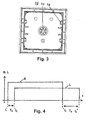
- the switch control element 12 has a central interface 13 (dome) Contact with interface 5. Furthermore, are attached on the edge Brackets 14 are provided for mounting on the flush-mounted insert 1.
- the lighting is switched on at time t 1 . This is done either by manually operating the switch control element 12 or automatically by detecting a person using the motion detector (see motion detector control element 7). After a defined switch-on delay T E has elapsed, the electronics of the combination insert 5 switches on the fan at time t 2 . At time t 3 , the lighting is switched off, which is done either by manual actuation of the switch control element 12 or automatically by the motion detector (see motion detector control element 7), which detects that the previously detected person is moving away from the area to be monitored. After a defined switch-off delay T N (follow-up time) has elapsed, the electronics of the combination insert 5 switch off the fan at time t 4 .
- T N follow-up time
- the switch-on delay T E is expediently defined such that the fan does not start if the lighting is switched off again before the switch-on delay T E has expired.
- Output II is only activated when the current switch-on time of the lighting exceeds the switch-on delay T E. This prevents unnecessary operation of the fan.
Landscapes
- Circuit Arrangement For Electric Light Sources In General (AREA)
- Arrangement Of Elements, Cooling, Sealing, Or The Like Of Lighting Devices (AREA)
- Circuit Arrangements For Discharge Lamps (AREA)
- Control Of Positive-Displacement Air Blowers (AREA)
Abstract
Description
- Fig.1
- eine Sicht auf einen Unterputzeinsatz,
- Fig. 2
- eine Sicht auf ein Bewegungsmelder-Bedienelement,
- Fig.3
- eine Sicht auf ein Schalter-Bedienelement,
- Fig. 4
- den zeitlichen Verlauf der Ein/Aus-Signale von Beleuchtung und Lüfter.
Claims (4)
- Unterputzeinsatz für kombinierte Beleuchtung/Lüfter-Ansteuerung mit einem Kombieinsatz (2), welcher mit Anschlüssen (4) für Beleuchtung, Lüfter und Netz, mit einer Schnittstelle (5) zum Anschluß eines die Beleuchtung schaltenden Bedienelementes (7, 12), und mit mindestens einem Potentiometer (6) zur Auswahl der Betriebsarten, insbesondere zur Vorgabe von unterschiedlichen Einschaltverzögerungen (TE) und Nachlaufzeiten (TN) für den Lüfter versehen ist, wobei der Kornbieinsatz (2) die zur Bildung von Einschaltverzögerungen und Nachlaufzeiten erforderliche Elektronik aufweist.
- Unterputzeinsatz nach Anspruch 1, gekennzeichnet durch ein manuell betätigbares Schalter-Bedienelement (12) mit einer Schnittstelle (13) zur Kontaktierung der Schnittstelle (5) des Unterputzeinsatzes.
- Unterputzeinsatz nach Anspruch 1, gekennzeichnet durch ein Bewegungsmelder-Bedienelement (7) mit einer Schnittstelle (8) zur Kontaktierung der Schnittstelle (5) des Unterputzeinsatzes.
- Unterputzeinsatz nach einem der vorstehenden Ansprüchen, gekennzeichnet durch Klammern (11, 14) zur Befestigung eines Bedienelementes (7, 12) am Unterputzeinsatz.
Applications Claiming Priority (2)
| Application Number | Priority Date | Filing Date | Title |
|---|---|---|---|
| DE10107805A DE10107805A1 (de) | 2001-02-20 | 2001-02-20 | Unterputzeinsatz |
| DE10107805 | 2001-02-20 |
Publications (3)
| Publication Number | Publication Date |
|---|---|
| EP1233655A2 true EP1233655A2 (de) | 2002-08-21 |
| EP1233655A3 EP1233655A3 (de) | 2007-05-09 |
| EP1233655B1 EP1233655B1 (de) | 2010-05-12 |
Family
ID=7674627
Family Applications (1)
| Application Number | Title | Priority Date | Filing Date |
|---|---|---|---|
| EP02002675A Expired - Lifetime EP1233655B1 (de) | 2001-02-20 | 2002-02-06 | Unterputzeinsatz für Kombinierte Beleuchtung/Lüfter-Ansteuerung |
Country Status (3)
| Country | Link |
|---|---|
| EP (1) | EP1233655B1 (de) |
| AT (1) | ATE468004T1 (de) |
| DE (2) | DE10107805A1 (de) |
Families Citing this family (1)
| Publication number | Priority date | Publication date | Assignee | Title |
|---|---|---|---|---|
| DE202012100439U1 (de) * | 2012-02-09 | 2013-05-10 | Gira Giersiepen Gmbh & Co. Kg | Elektrisches Steuergerät |
Family Cites Families (7)
| Publication number | Priority date | Publication date | Assignee | Title |
|---|---|---|---|---|
| GB2067356B (en) * | 1979-11-30 | 1984-02-01 | Matsushita Electric Works Ltd | Time delay switches |
| DE3836625A1 (de) * | 1987-11-01 | 1989-05-11 | Maico Elektroapparate | Steuervorrichtung |
| DE3913175A1 (de) * | 1988-04-22 | 1990-02-08 | Richard Von Liechtenstein | Zeitschaltvorrichtung |
| US4990908A (en) * | 1989-03-23 | 1991-02-05 | Michael Tung | Remote power control for dual loads |
| DE4117572A1 (de) * | 1991-05-29 | 1992-12-03 | Abb Patent Gmbh | Elektrisches geraet zur stufenlosen lasteinstellung |
| US5338910A (en) * | 1993-02-12 | 1994-08-16 | Powell Tsai | Wall controller |
| DE19845960A1 (de) * | 1998-10-06 | 2000-04-13 | Insta Elektro Gmbh & Co Kg | Elektrisches Installationssystem |
-
2001
- 2001-02-20 DE DE10107805A patent/DE10107805A1/de not_active Withdrawn
-
2002
- 2002-02-06 AT AT02002675T patent/ATE468004T1/de active
- 2002-02-06 DE DE50214421T patent/DE50214421D1/de not_active Expired - Lifetime
- 2002-02-06 EP EP02002675A patent/EP1233655B1/de not_active Expired - Lifetime
Also Published As
| Publication number | Publication date |
|---|---|
| DE50214421D1 (de) | 2010-06-24 |
| DE10107805A1 (de) | 2002-09-05 |
| EP1233655B1 (de) | 2010-05-12 |
| EP1233655A3 (de) | 2007-05-09 |
| ATE468004T1 (de) | 2010-05-15 |
Similar Documents
| Publication | Publication Date | Title |
|---|---|---|
| EP2438664B1 (de) | Elektro-installationseinheit | |
| EP2211084B1 (de) | Leuchte, insbesondere Wandleuchte | |
| EP0853022B1 (de) | Funktionsmodul für Kraftfahrzeuge | |
| EP0905875B1 (de) | Elektrischer Bremswiderstand | |
| EP0402654B1 (de) | Anschlussvorrichtung für den Anschluss elektrischer Verbraucher | |
| EP0625817A1 (de) | Bedieneinheit für Installationsgeräte | |
| DE102023110987B3 (de) | Funktionsmodul, Anordnung umfassend ein solches und ein Schaltgerät sowie Verfahren zur Montage | |
| DE10329358B4 (de) | Elektrische/elektronische Einrichtung | |
| DE102005062494B4 (de) | Elektrisches/elektronisches Installationsgerät | |
| EP3799534A1 (de) | Funktionsmodul | |
| DE19708210C2 (de) | Regler, insbesondere Temperaturregler wie Raumtemperaturregler | |
| EP1233655A2 (de) | Unterputzeinsatz | |
| EP1843366B1 (de) | Elektrisches/elektronisches Installationsgerät mit Bewegungsmelder und manueller Schalteinrichtung | |
| DE102005062489B4 (de) | Elektrisches / elektronisches Installationsgerät | |
| DE3241159A1 (de) | Befehlstaster zum einbau in eine schalttafel oder dergleichen | |
| DE102017103699B4 (de) | Elektrisches/elektronisches Steuergerät | |
| DE10020217B4 (de) | Gegliederter Abdeckrahmen für elektrische Unterputz-Installationsgeräte | |
| EP0809266A2 (de) | Niederspannungsschaltgerät | |
| DE3445601A1 (de) | Raumtemperaturregler | |
| DE29602673U1 (de) | Programmierbares Lichtsteuersystem | |
| EP2395627A1 (de) | Installationsgerät sowie Einsatzgerät und Aufsatzgerät für ein Installationsgerät | |
| DE9321350U1 (de) | Bedieneinheit für Installationsgeräte | |
| EP3482471B1 (de) | Aufnahmemodul, funktionsmodul sowie ein elektrisches/elektronisches installationsgerät | |
| EP0825688A2 (de) | Elektronisches Vorschaltgerät für Tragschienenleuchten | |
| DE102006062751A1 (de) | Multidimmer, welcher universell als Masterdimmer, als Slavedimmer oder als Nebenstelle einsetzbar ist |
Legal Events
| Date | Code | Title | Description |
|---|---|---|---|
| PUAI | Public reference made under article 153(3) epc to a published international application that has entered the european phase |
Free format text: ORIGINAL CODE: 0009012 |
|
| AK | Designated contracting states |
Kind code of ref document: A2 Designated state(s): AT BE CH CY DE DK ES FI FR GB GR IE IT LI LU MC NL PT SE TR |
|
| AX | Request for extension of the european patent |
Free format text: AL PAYMENT 20020216;LT PAYMENT 20020216;LV PAYMENT 20020216;MK PAYMENT 20020216;RO PAYMENT 20020216;SI PAYMENT 20020216 |
|
| PUAL | Search report despatched |
Free format text: ORIGINAL CODE: 0009013 |
|
| AK | Designated contracting states |
Kind code of ref document: A3 Designated state(s): AT BE CH CY DE DK ES FI FR GB GR IE IT LI LU MC NL PT SE TR |
|
| AX | Request for extension of the european patent |
Extension state: AL LT LV MK RO SI |
|
| RIC1 | Information provided on ipc code assigned before grant |
Ipc: H01H 25/06 20060101ALI20070330BHEP Ipc: H05B 37/02 20060101AFI20020529BHEP |
|
| 17P | Request for examination filed |
Effective date: 20070622 |
|
| 17Q | First examination report despatched |
Effective date: 20071025 |
|
| AKX | Designation fees paid |
Designated state(s): AT BE CH CY DE DK ES FI FR GB GR IE IT LI LU MC NL PT SE TR |
|
| AXX | Extension fees paid |
Extension state: RO Payment date: 20020216 Extension state: LT Payment date: 20020216 Extension state: SI Payment date: 20020216 Extension state: AL Payment date: 20020216 Extension state: MK Payment date: 20020216 Extension state: LV Payment date: 20020216 |
|
| GRAP | Despatch of communication of intention to grant a patent |
Free format text: ORIGINAL CODE: EPIDOSNIGR1 |
|
| RTI1 | Title (correction) |
Free format text: FLUSH MOUNTING FOR COMBINED LIGHT/VENTILATION CONTROL& X9;& X9; |
|
| GRAS | Grant fee paid |
Free format text: ORIGINAL CODE: EPIDOSNIGR3 |
|
| RTI1 | Title (correction) |
Free format text: FLUSH MOUNTING FOR COMBINED LIGHT/VENTILATION CONTROL |
|
| RAP1 | Party data changed (applicant data changed or rights of an application transferred) |
Owner name: ABB AG |
|
| GRAA | (expected) grant |
Free format text: ORIGINAL CODE: 0009210 |
|
| AK | Designated contracting states |
Kind code of ref document: B1 Designated state(s): AT BE CH CY DE DK ES FI FR GB GR IE IT LI LU MC NL PT SE TR |
|
| AX | Request for extension of the european patent |
Extension state: AL LT LV MK RO SI |
|
| REG | Reference to a national code |
Ref country code: GB Ref legal event code: FG4D Free format text: NOT ENGLISH |
|
| REG | Reference to a national code |
Ref country code: CH Ref legal event code: EP |
|
| REG | Reference to a national code |
Ref country code: IE Ref legal event code: FG4D Free format text: LANGUAGE OF EP DOCUMENT: GERMAN |
|
| REF | Corresponds to: |
Ref document number: 50214421 Country of ref document: DE Date of ref document: 20100624 Kind code of ref document: P |
|
| REG | Reference to a national code |
Ref country code: NL Ref legal event code: VDEP Effective date: 20100512 |
|
| LTIE | Lt: invalidation of european patent or patent extension |
Effective date: 20100512 |
|
| PG25 | Lapsed in a contracting state [announced via postgrant information from national office to epo] |
Ref country code: ES Free format text: LAPSE BECAUSE OF FAILURE TO SUBMIT A TRANSLATION OF THE DESCRIPTION OR TO PAY THE FEE WITHIN THE PRESCRIBED TIME-LIMIT Effective date: 20100823 Ref country code: NL Free format text: LAPSE BECAUSE OF FAILURE TO SUBMIT A TRANSLATION OF THE DESCRIPTION OR TO PAY THE FEE WITHIN THE PRESCRIBED TIME-LIMIT Effective date: 20100512 Ref country code: SE Free format text: LAPSE BECAUSE OF FAILURE TO SUBMIT A TRANSLATION OF THE DESCRIPTION OR TO PAY THE FEE WITHIN THE PRESCRIBED TIME-LIMIT Effective date: 20100512 |
|
| PG25 | Lapsed in a contracting state [announced via postgrant information from national office to epo] |
Ref country code: FI Free format text: LAPSE BECAUSE OF FAILURE TO SUBMIT A TRANSLATION OF THE DESCRIPTION OR TO PAY THE FEE WITHIN THE PRESCRIBED TIME-LIMIT Effective date: 20100512 |
|
| REG | Reference to a national code |
Ref country code: IE Ref legal event code: FD4D |
|
| PG25 | Lapsed in a contracting state [announced via postgrant information from national office to epo] |
Ref country code: CY Free format text: LAPSE BECAUSE OF FAILURE TO SUBMIT A TRANSLATION OF THE DESCRIPTION OR TO PAY THE FEE WITHIN THE PRESCRIBED TIME-LIMIT Effective date: 20100512 Ref country code: GR Free format text: LAPSE BECAUSE OF FAILURE TO SUBMIT A TRANSLATION OF THE DESCRIPTION OR TO PAY THE FEE WITHIN THE PRESCRIBED TIME-LIMIT Effective date: 20100813 |
|
| PG25 | Lapsed in a contracting state [announced via postgrant information from national office to epo] |
Ref country code: IE Free format text: LAPSE BECAUSE OF FAILURE TO SUBMIT A TRANSLATION OF THE DESCRIPTION OR TO PAY THE FEE WITHIN THE PRESCRIBED TIME-LIMIT Effective date: 20100512 Ref country code: PT Free format text: LAPSE BECAUSE OF FAILURE TO SUBMIT A TRANSLATION OF THE DESCRIPTION OR TO PAY THE FEE WITHIN THE PRESCRIBED TIME-LIMIT Effective date: 20100913 Ref country code: DK Free format text: LAPSE BECAUSE OF FAILURE TO SUBMIT A TRANSLATION OF THE DESCRIPTION OR TO PAY THE FEE WITHIN THE PRESCRIBED TIME-LIMIT Effective date: 20100512 |
|
| PLBE | No opposition filed within time limit |
Free format text: ORIGINAL CODE: 0009261 |
|
| STAA | Information on the status of an ep patent application or granted ep patent |
Free format text: STATUS: NO OPPOSITION FILED WITHIN TIME LIMIT |
|
| PG25 | Lapsed in a contracting state [announced via postgrant information from national office to epo] |
Ref country code: IT Free format text: LAPSE BECAUSE OF FAILURE TO SUBMIT A TRANSLATION OF THE DESCRIPTION OR TO PAY THE FEE WITHIN THE PRESCRIBED TIME-LIMIT Effective date: 20100512 |
|
| 26N | No opposition filed |
Effective date: 20110215 |
|
| REG | Reference to a national code |
Ref country code: DE Ref legal event code: R097 Ref document number: 50214421 Country of ref document: DE Effective date: 20110214 |
|
| BERE | Be: lapsed |
Owner name: ABB A.G. Effective date: 20110228 |
|
| PG25 | Lapsed in a contracting state [announced via postgrant information from national office to epo] |
Ref country code: MC Free format text: LAPSE BECAUSE OF NON-PAYMENT OF DUE FEES Effective date: 20110228 |
|
| REG | Reference to a national code |
Ref country code: CH Ref legal event code: PL |
|
| GBPC | Gb: european patent ceased through non-payment of renewal fee |
Effective date: 20110206 |
|
| PG25 | Lapsed in a contracting state [announced via postgrant information from national office to epo] |
Ref country code: CH Free format text: LAPSE BECAUSE OF NON-PAYMENT OF DUE FEES Effective date: 20110228 Ref country code: LI Free format text: LAPSE BECAUSE OF NON-PAYMENT OF DUE FEES Effective date: 20110228 |
|
| REG | Reference to a national code |
Ref country code: FR Ref legal event code: ST Effective date: 20111102 |
|
| PG25 | Lapsed in a contracting state [announced via postgrant information from national office to epo] |
Ref country code: BE Free format text: LAPSE BECAUSE OF NON-PAYMENT OF DUE FEES Effective date: 20110228 |
|
| PG25 | Lapsed in a contracting state [announced via postgrant information from national office to epo] |
Ref country code: FR Free format text: LAPSE BECAUSE OF NON-PAYMENT OF DUE FEES Effective date: 20110228 |
|
| PG25 | Lapsed in a contracting state [announced via postgrant information from national office to epo] |
Ref country code: GB Free format text: LAPSE BECAUSE OF NON-PAYMENT OF DUE FEES Effective date: 20110206 |
|
| REG | Reference to a national code |
Ref country code: AT Ref legal event code: MM01 Ref document number: 468004 Country of ref document: AT Kind code of ref document: T Effective date: 20110206 |
|
| PG25 | Lapsed in a contracting state [announced via postgrant information from national office to epo] |
Ref country code: AT Free format text: LAPSE BECAUSE OF NON-PAYMENT OF DUE FEES Effective date: 20110206 |
|
| PG25 | Lapsed in a contracting state [announced via postgrant information from national office to epo] |
Ref country code: LU Free format text: LAPSE BECAUSE OF NON-PAYMENT OF DUE FEES Effective date: 20110206 |
|
| PG25 | Lapsed in a contracting state [announced via postgrant information from national office to epo] |
Ref country code: TR Free format text: LAPSE BECAUSE OF FAILURE TO SUBMIT A TRANSLATION OF THE DESCRIPTION OR TO PAY THE FEE WITHIN THE PRESCRIBED TIME-LIMIT Effective date: 20100512 |
|
| REG | Reference to a national code |
Ref country code: DE Ref legal event code: R084 Ref document number: 50214421 Country of ref document: DE |
|
| REG | Reference to a national code |
Ref country code: DE Ref legal event code: R081 Ref document number: 50214421 Country of ref document: DE Owner name: ABB SCHWEIZ AG, CH Free format text: FORMER OWNER: ABB AG, 68165 MANNHEIM, DE |
|
| PGFP | Annual fee paid to national office [announced via postgrant information from national office to epo] |
Ref country code: DE Payment date: 20210217 Year of fee payment: 20 |