EP1233233A1 - Luminaire encastrable au moins partiellement dans une cloison sèche - Google Patents
Luminaire encastrable au moins partiellement dans une cloison sèche Download PDFInfo
- Publication number
- EP1233233A1 EP1233233A1 EP02290322A EP02290322A EP1233233A1 EP 1233233 A1 EP1233233 A1 EP 1233233A1 EP 02290322 A EP02290322 A EP 02290322A EP 02290322 A EP02290322 A EP 02290322A EP 1233233 A1 EP1233233 A1 EP 1233233A1
- Authority
- EP
- European Patent Office
- Prior art keywords
- luminaire
- front face
- projecting part
- partition
- housing
- Prior art date
- Legal status (The legal status is an assumption and is not a legal conclusion. Google has not performed a legal analysis and makes no representation as to the accuracy of the status listed.)
- Granted
Links
- 238000005192 partition Methods 0.000 claims description 32
- 238000010438 heat treatment Methods 0.000 description 4
- 230000017525 heat dissipation Effects 0.000 description 2
- 238000009434 installation Methods 0.000 description 2
- 238000013459 approach Methods 0.000 description 1
- 210000000078 claw Anatomy 0.000 description 1
- 238000001816 cooling Methods 0.000 description 1
- 210000002445 nipple Anatomy 0.000 description 1
- 238000013021 overheating Methods 0.000 description 1
- 239000011505 plaster Substances 0.000 description 1
- 238000009423 ventilation Methods 0.000 description 1
Images

Classifications
-
- F—MECHANICAL ENGINEERING; LIGHTING; HEATING; WEAPONS; BLASTING
- F21—LIGHTING
- F21V—FUNCTIONAL FEATURES OR DETAILS OF LIGHTING DEVICES OR SYSTEMS THEREOF; STRUCTURAL COMBINATIONS OF LIGHTING DEVICES WITH OTHER ARTICLES, NOT OTHERWISE PROVIDED FOR
- F21V29/00—Protecting lighting devices from thermal damage; Cooling or heating arrangements specially adapted for lighting devices or systems
- F21V29/50—Cooling arrangements
- F21V29/70—Cooling arrangements characterised by passive heat-dissipating elements, e.g. heat-sinks
- F21V29/83—Cooling arrangements characterised by passive heat-dissipating elements, e.g. heat-sinks the elements having apertures, ducts or channels, e.g. heat radiation holes
-
- F—MECHANICAL ENGINEERING; LIGHTING; HEATING; WEAPONS; BLASTING
- F21—LIGHTING
- F21S—NON-PORTABLE LIGHTING DEVICES; SYSTEMS THEREOF; VEHICLE LIGHTING DEVICES SPECIALLY ADAPTED FOR VEHICLE EXTERIORS
- F21S8/00—Lighting devices intended for fixed installation
- F21S8/02—Lighting devices intended for fixed installation of recess-mounted type, e.g. downlighters
-
- F—MECHANICAL ENGINEERING; LIGHTING; HEATING; WEAPONS; BLASTING
- F21—LIGHTING
- F21V—FUNCTIONAL FEATURES OR DETAILS OF LIGHTING DEVICES OR SYSTEMS THEREOF; STRUCTURAL COMBINATIONS OF LIGHTING DEVICES WITH OTHER ARTICLES, NOT OTHERWISE PROVIDED FOR
- F21V21/00—Supporting, suspending, or attaching arrangements for lighting devices; Hand grips
- F21V21/02—Wall, ceiling, or floor bases; Fixing pendants or arms to the bases
- F21V21/04—Recessed bases
Definitions
- the present invention relates to a luminaire that can at least partially recessed in a drywall.
- the light fixtures known are of substantially parallelepiped shape with edges possibly rounded so as to present an elongated front face and rounded at the ends.
- a shaped hole corresponding is cut in the partition and the luminaire is introduced by translation in the opening made.
- the shape of the opening corresponds substantially to the shape of the section of the luminaire.
- the main technical problem encountered with luminaires recessed luminaires of the prior art is a problem of heating of the luminaire at inside the partition. Indeed, the interior space of the partition not being ventilated, the luminaire tends to heat up.
- the object of the present invention is therefore to provide a luminaire capable of be built-in for which the heating inside the partition is limited, even when the space to house the luminaire is limited.
- a luminaire intended to be at least partially embedded in a drywall with a front side intended to be at the level of the external surface of the partition as well as a housing intended to be embedded in the partition by an opening made previously in it.
- the recessed housing of the luminaire in its position installed in the partition, has a projecting part which is housed facing the partition, inside thereof and on one side of the opening, and the projecting part has, on the side opposite the front face of the luminaire, a profiled face rounded.
- This projecting part increases the exchange surface between the luminaire and its environment.
- the heat given off by the during operation it drains better, thus limiting overheating of the luminaire.
- the shape of the projection allows the introduction of the housing in a partition even in the case of a limited space (especially in depth) to accommodate this case.
- the projecting part presented by example, on the side of the front face of the luminaire, a substantially flat face and substantially parallel to this front face.
- the edge of the recessed box opposite the front face of the luminaire and opposite the projecting part is preferably rounded.
- the projecting part is advantageously perforated on at least part of its area.
- Access to the interior of the luminaire, and in particular of its housing, is allowed for example thanks to an opening made on the projecting part.
- provision can be made for the face of the projecting part opposite to the front face of the luminaire is constituted by a removable cover.
- the front face of the luminaire is substantially rectangular and the projecting part extends over a long side of this front face, over more than half the length of this long side.
- the height of the projecting part corresponds for example substantially at the height of the front face of the luminaire to obtain good heat exchange in the partition between the luminaire and its environment.
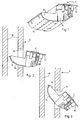
- Figure 1 shows a luminaire 2 intended to be recessed in a partition 4.
- the latter can be a vertical or horizontal partition in the case where it is a ceiling.
- the invention is however more particularly oriented towards luminaires recessed in a vertical partition, or wall, because it is in this case that the problems of heating of the luminaire appear usually. Indeed, the ventilation at the level of the ceilings is better than in vertical partitions. In this case, it is a dry wall 4 vertical.
- the luminaire 2 has a front face 6, a housing 8, closed by the front face 6, and a projecting part 10.
- the front face 6 is of substantially rectangular shape. On the Figures 2 to 6, we only see a small side of this rectangle. This front face 6 includes in particular a transparent or translucent zone surrounded by an edge opaque. This front face 6 is the part of the luminaire which will remain visible once this one recessed. Its shape depends on the aesthetics that one wishes to give to the lamp.
- the housing 8 is disposed behind the front face 6. It contains preferably all the various electrical components necessary for operation of luminaire 2. These components, connections, bulbs, etc. are known from skilled in the art and are not further described here. They depend including the type of bulb used.
- This box 8 is substantially rectangular and its size is adapted the dimensions of the front panel and the depth available for installation of the luminaire.
- the length and width of this case are slightly less than length and width of the front panel.
- the front face forms a rim 12 on at least two sides of the housing.
- the protruding part 10 extends from one face of the housing 8 corresponding to a large side of the front face 6. This projecting part extends parallel to the front face 6 and over almost the entire length of the face corresponding to the housing 8. So, looking at the luminaire from the front, the front 6 hides the housing 8 and we see the protruding part 10 beyond the outline of the front face.
- the height of the projecting part which protrudes from the face before 6 corresponds for example substantially to the width of the rectangle forming this front face.
- This projecting part 10 is preferably substantially empty. As indicated above, the components necessary for the operation of the luminaire are located in box 8. Only possibly cables supply (not shown) pass inside the protruding part 10.
- the rear face of the luminaire, as opposed to the front face 6, is convex.
- the two edges of the assembly formed by the housing 8 and the projecting part 10, extending parallel to the long sides of the rectangle of the front face 6 are in fact rounded to facilitate mounting of the luminaire 2 in the partition 4.
- the front back of the luminaire is perforated at the level of the projecting part 10. Air can thus circulate inside this projection.
- the rear side of this projecting part 10, that is to say the rounded face opposite the front face 6, consists of a removable cover 14.
- the latter is for example fixed on the one hand by two claws cooperating with an edge of the housing 8 and on the other hand by two nipples coming snap onto the front face of the protruding part 10. Any other fixing of the hood may be considered.
- This cover 14 is provided to allow access to the inside of the housing 8 for making connections for example inside this before mounting. This access is facilitated by the absence of components in the projection level 10.
- the mounting of the luminaire 2 in the partition 4 is then carried out by example according to the operating mode described below with reference to FIGS. 2 to 6.
- a first step consists in carrying out an opening 16 in one of the two walls 18 of the partition 4.
- the drywall in which the luminaire 2 is placed has two walls 18 parallel connected together by various means, for example a honeycomb cardboard.
- the walls 18 are for example made of plaster.
- the walls 18 have for example a thickness of 13 or 15 mm while the free space between these two walls 18 is 48 mm.
- the opening 16 made is of a size corresponding to that of the housing 8.
- the size of this opening is less than that of the front face 6. Indeed, once the luminaire in place, the edge of the opening 16 should no longer be visible but hidden by the edge 12.
- the luminaire 2 To introduce the luminaire 2 into the partition 4 passing through opening 16, the luminaire is presented in the position shown on the Figure 2.
- the front face 6 is then substantially perpendicular to the partition 4 and the projecting part 10 is introduced into the opening 16.
- the introduction of the luminaire into the partition 4 then results from a helical movement which is the combination of a translation of the luminaire 2 towards inside the partition 4 and a pivoting of the whole light fixture around an axis perpendicular to the drawing plane in a clockwise direction shows. It is recalled here that the drawing plane corresponds to a plane perpendicular to the front face 6 of the luminaire 2.
- Figure 3 shows the luminaire when the front face 6 is tilted about 45 ° relative to the partition 4.
- the front face of the protruding part 10 is in contact with or almost in contact with the upper edge of the opening 16.
- partition 4 is a vertical partition and that the luminaire must be mounted so that the long sides of the rectangle of the front face 6 are, in the mounted position, substantially horizontal.
- the projecting part 10 is located above the housing 8.
- the rounded rear edge of the protruding part 10 approaches the wall 18 having no opening 16.
- the rear rounded edge of the housing 8 is is located at the lower edge of the opening 16. The presence of these rounded edges facilitate the passage of the luminaire 2 through the opening 16 and allows the installation of a luminaire of larger dimensions than with edges at right angles for an opening of the same dimensions.
- the convex rounded shape of the rear side of the luminaire allows, during the movement of introduction of the luminaire in partition 4, to maintain this rear face substantially tangent on the one hand to the wall 18 not provided with the opening 16 at the level of the part protruding 10 and on the other hand at the edge of the opening 16 at the housing 8.
Landscapes
- Engineering & Computer Science (AREA)
- General Engineering & Computer Science (AREA)
- Arrangement Of Elements, Cooling, Sealing, Or The Like Of Lighting Devices (AREA)
Abstract
Description
Claims (8)
- Luminaire (2) destiné à être au moins partiellement encastré dans une cloison sèche (4) comportant une face avant (6) destinée à se trouver au niveau de la surface extérieure de la cloison (4) ainsi qu'un boítier (8) destiné à être encastré dans la cloison (4) par une ouverture (16) réalisée préalablement dans celle-ci,
caractérisé en ce que le boítier (8) encastré du luminaire, dans sa position installée dans la cloison, présente une partie en saillie (10) venant se loger face à la cloison, à l'intérieur de celle-ci et sur un côté de l'ouverture (16), et en ce que la partie en saillie (10) présente, du côté opposé à la face avant (6) du luminaire, une face de forme profilée arrondie. - Luminaire selon la revendication 1, caractérisé en ce que la partie en saillie (10) présente, du côté de la face avant (6) du luminaire, une face sensiblement plane et sensiblement parallèle à cette face avant.
- Luminaire selon l'une des revendications 1 ou 2, caractérisé en ce que la partie en saillie (10) est ajourée sur au moins une partie de sa surface.
- Luminaire selon l'une des revendications 1 à 3, caractérisé en ce que le bord du boítier à encastrer opposé à la face avant (6) du luminaire et opposé à la partie en saillie (10), est arrondi.
- Luminaire selon l'une des revendications 1 à 4, caractérisé en ce qu'une ouverture est réalisée sur la partie en saillie pour permettre d'accéder à l'intérieur du boítier (8).
- Luminaire selon la revendication 5, caractérisé en ce que la face de la partie en saillie (10) opposée à la face avant (6) du luminaire est constituée par un capot (14) amovible.
- Luminaire selon l'une des revendications 1 à 6, caractérisé en ce que sa face avant (6) est sensiblement rectangulaire et en ce que la partie en saillie (10) s'étend sur un grand côté de cette face avant, sur plus de la moitié de la longueur de ce grand côté.
- Luminaire selon l'une des revendications 1 à 7, caractérisé en ce que la hauteur de la partie en saillie (10) correspond sensiblement à la hauteur de la face avant (6) du luminaire.
Applications Claiming Priority (2)
| Application Number | Priority Date | Filing Date | Title |
|---|---|---|---|
| FR0102123A FR2821146B1 (fr) | 2001-02-16 | 2001-02-16 | Luminaire encastrable au moins partiellement dans une cloison seche |
| FR0102123 | 2001-02-16 |
Publications (2)
| Publication Number | Publication Date |
|---|---|
| EP1233233A1 true EP1233233A1 (fr) | 2002-08-21 |
| EP1233233B1 EP1233233B1 (fr) | 2008-10-08 |
Family
ID=8860101
Family Applications (1)
| Application Number | Title | Priority Date | Filing Date |
|---|---|---|---|
| EP02290322A Expired - Lifetime EP1233233B1 (fr) | 2001-02-16 | 2002-02-08 | Luminaire encastrable au moins partiellement dans une cloison sèche |
Country Status (4)
| Country | Link |
|---|---|
| EP (1) | EP1233233B1 (fr) |
| DE (1) | DE60229179D1 (fr) |
| DK (1) | DK1233233T3 (fr) |
| FR (1) | FR2821146B1 (fr) |
Cited By (1)
| Publication number | Priority date | Publication date | Assignee | Title |
|---|---|---|---|---|
| EP1906083A1 (fr) | 2006-09-29 | 2008-04-02 | Patent-Treuhand-Gesellschaft für elektrische Glühlampen mbH | Dissipateur de chaleur et dispositif d'éclairage avec un dissipateur de chaleur |
Citations (4)
| Publication number | Priority date | Publication date | Assignee | Title |
|---|---|---|---|---|
| DE2107681A1 (de) * | 1970-11-16 | 1972-07-20 | Leuchtenbau Leipzig K Veb | Decken-Einbauleuchte |
| US3815857A (en) * | 1971-12-07 | 1974-06-11 | Esquire Inc | Light fixtures |
| US4748543A (en) * | 1987-06-29 | 1988-05-31 | Swarens Ralph W | Hidden source fluorescent light wash fixture |
| FR2795160A1 (fr) * | 1999-06-15 | 2000-12-22 | Sidler Gmbh & Co | Boitier de lampe destine a etre encastre dans une ouverture d'encastrement |
Family Cites Families (3)
| Publication number | Priority date | Publication date | Assignee | Title |
|---|---|---|---|---|
| DE4413290C2 (de) * | 1994-04-16 | 1999-10-28 | Zumtobel Licht Gmbh Dornbirn | Halogenleuchte |
| JPH10214516A (ja) * | 1997-01-31 | 1998-08-11 | Matsushita Electric Works Ltd | 埋込型照明器具 |
| DE29902563U1 (de) * | 1999-02-13 | 1999-05-06 | Wila Leuchten Ag, Sevelen | Deckeneinbauleuchte |
-
2001
- 2001-02-16 FR FR0102123A patent/FR2821146B1/fr not_active Expired - Fee Related
-
2002
- 2002-02-08 DK DK02290322T patent/DK1233233T3/da active
- 2002-02-08 DE DE60229179T patent/DE60229179D1/de not_active Expired - Lifetime
- 2002-02-08 EP EP02290322A patent/EP1233233B1/fr not_active Expired - Lifetime
Patent Citations (4)
| Publication number | Priority date | Publication date | Assignee | Title |
|---|---|---|---|---|
| DE2107681A1 (de) * | 1970-11-16 | 1972-07-20 | Leuchtenbau Leipzig K Veb | Decken-Einbauleuchte |
| US3815857A (en) * | 1971-12-07 | 1974-06-11 | Esquire Inc | Light fixtures |
| US4748543A (en) * | 1987-06-29 | 1988-05-31 | Swarens Ralph W | Hidden source fluorescent light wash fixture |
| FR2795160A1 (fr) * | 1999-06-15 | 2000-12-22 | Sidler Gmbh & Co | Boitier de lampe destine a etre encastre dans une ouverture d'encastrement |
Cited By (5)
| Publication number | Priority date | Publication date | Assignee | Title |
|---|---|---|---|---|
| EP1906083A1 (fr) | 2006-09-29 | 2008-04-02 | Patent-Treuhand-Gesellschaft für elektrische Glühlampen mbH | Dissipateur de chaleur et dispositif d'éclairage avec un dissipateur de chaleur |
| JP2008135710A (ja) * | 2006-09-29 | 2008-06-12 | Patent Treuhand Ges Elektr Gluehlamp Mbh | ヒートシンク及びヒートシンクを備えた照明システム |
| AU2007214290B2 (en) * | 2006-09-29 | 2013-05-16 | Patent-Treuhand-Gesellschaft Fur Elektrische Gluhlampen Mbh | Heatsink and illumination system with a heatsink |
| CN101153704B (zh) * | 2006-09-29 | 2013-11-20 | 电灯专利信托有限公司 | 散热装置和带有散热装置的照明系统 |
| US8596834B2 (en) | 2006-09-29 | 2013-12-03 | Osram Gesellschaft mit beschränkter Haftung | Heatsink and illumination system with a heatsink |
Also Published As
| Publication number | Publication date |
|---|---|
| EP1233233B1 (fr) | 2008-10-08 |
| DK1233233T3 (da) | 2009-01-05 |
| FR2821146B1 (fr) | 2003-10-03 |
| FR2821146A1 (fr) | 2002-08-23 |
| DE60229179D1 (de) | 2008-11-20 |
Similar Documents
| Publication | Publication Date | Title |
|---|---|---|
| USD578237S1 (en) | Tri-light lighting fixture | |
| EP2977518B1 (fr) | Lisse lumineuse pour fausse-paroi à toile tendue et fausse-paroi comprenant une telle lisse | |
| EP2659071B1 (fr) | Dispositif de fausse paroi a triple epaisseur | |
| CA2041906A1 (fr) | Dispositif d'eclairage | |
| EP3049715B1 (fr) | Projecteur de véhicule automobile muni d'un accessoire de décoration | |
| FR2744788A3 (fr) | Luminaire protege contre les degradations | |
| FR2795160A1 (fr) | Boitier de lampe destine a etre encastre dans une ouverture d'encastrement | |
| EP1233233B1 (fr) | Luminaire encastrable au moins partiellement dans une cloison sèche | |
| EP0159594B1 (fr) | Appareil d'éclairage à haut pouvoir de diffusion | |
| FR2577028A3 (fr) | Refrigerateur | |
| FR2947610A1 (fr) | Dispositif d'eclairage pour salle propre | |
| EP1164676A1 (fr) | Dispositif de montage d'un appareil électrique sur un conduit de câblage | |
| FR2683021A1 (fr) | Hublot d'eclairage. | |
| EP2988648B1 (fr) | Dispositif de lavage d'articles | |
| FR2650579A1 (fr) | Plafond a eclairage integre, notamment pour cabine d'ascenseur | |
| FR2595133A1 (fr) | Module encastrable renfermant un equipement, notamment d'eclairage | |
| EP0699866B1 (fr) | Système d'accrochage mural pour applique d'éclairage | |
| BE1025233A1 (fr) | Disposif de fixation de luminaire sans outil | |
| EP0623781B1 (fr) | Dispositif d'éclairage ou de signalisation comprenant des moyens perfectionnés de maintien d'un écran intermédiaire | |
| FR2726235A3 (fr) | Feu d'eclairage de vehicule | |
| FR2934822A3 (fr) | Dispositif de signalisation lumineux pour vehicule automobile | |
| EP1515091B1 (fr) | Four encastrable à parois latérales ventilées | |
| EP0793054A2 (fr) | Dispositif occulteur pour projecteur de véhicule automobile et projecteur ainsi equipe | |
| FR2704626A1 (fr) | Plafonnier multifonction de type protégé contre la pénétration des éclaboussures d'eau, particulièrement applicable à des supports de salles de bains. | |
| EP0565438A1 (fr) | Feu de signalisation monté sur une plage arrière de véhicule automobile |
Legal Events
| Date | Code | Title | Description |
|---|---|---|---|
| PUAI | Public reference made under article 153(3) epc to a published international application that has entered the european phase |
Free format text: ORIGINAL CODE: 0009012 |
|
| AK | Designated contracting states |
Kind code of ref document: A1 Designated state(s): AT BE CH CY DE DK ES FI FR GB GR IE IT LI LU MC NL PT SE TR |
|
| AX | Request for extension of the european patent |
Free format text: AL;LT;LV;MK;RO;SI |
|
| 17P | Request for examination filed |
Effective date: 20021005 |
|
| AKX | Designation fees paid |
Designated state(s): DE DK IT |
|
| 17Q | First examination report despatched |
Effective date: 20061127 |
|
| GRAP | Despatch of communication of intention to grant a patent |
Free format text: ORIGINAL CODE: EPIDOSNIGR1 |
|
| GRAS | Grant fee paid |
Free format text: ORIGINAL CODE: EPIDOSNIGR3 |
|
| GRAA | (expected) grant |
Free format text: ORIGINAL CODE: 0009210 |
|
| AK | Designated contracting states |
Kind code of ref document: B1 Designated state(s): DE DK IT |
|
| REF | Corresponds to: |
Ref document number: 60229179 Country of ref document: DE Date of ref document: 20081120 Kind code of ref document: P |
|
| REG | Reference to a national code |
Ref country code: DK Ref legal event code: T3 |
|
| PLBE | No opposition filed within time limit |
Free format text: ORIGINAL CODE: 0009261 |
|
| STAA | Information on the status of an ep patent application or granted ep patent |
Free format text: STATUS: NO OPPOSITION FILED WITHIN TIME LIMIT |
|
| 26N | No opposition filed |
Effective date: 20090709 |
|
| PGFP | Annual fee paid to national office [announced via postgrant information from national office to epo] |
Ref country code: DE Payment date: 20120120 Year of fee payment: 11 |
|
| PGFP | Annual fee paid to national office [announced via postgrant information from national office to epo] |
Ref country code: DK Payment date: 20120118 Year of fee payment: 11 Ref country code: IT Payment date: 20120222 Year of fee payment: 11 |
|
| REG | Reference to a national code |
Ref country code: DK Ref legal event code: EBP |
|
| REG | Reference to a national code |
Ref country code: DE Ref legal event code: R119 Ref document number: 60229179 Country of ref document: DE Effective date: 20130903 |
|
| PG25 | Lapsed in a contracting state [announced via postgrant information from national office to epo] |
Ref country code: IT Free format text: LAPSE BECAUSE OF NON-PAYMENT OF DUE FEES Effective date: 20130208 |
|
| PG25 | Lapsed in a contracting state [announced via postgrant information from national office to epo] |
Ref country code: DE Free format text: LAPSE BECAUSE OF NON-PAYMENT OF DUE FEES Effective date: 20130903 Ref country code: DK Free format text: LAPSE BECAUSE OF NON-PAYMENT OF DUE FEES Effective date: 20130228 |