EP1233191A2 - Hydraulischer Oszillator als Antrieb von Maschinen - Google Patents
Hydraulischer Oszillator als Antrieb von Maschinen Download PDFInfo
- Publication number
- EP1233191A2 EP1233191A2 EP01128622A EP01128622A EP1233191A2 EP 1233191 A2 EP1233191 A2 EP 1233191A2 EP 01128622 A EP01128622 A EP 01128622A EP 01128622 A EP01128622 A EP 01128622A EP 1233191 A2 EP1233191 A2 EP 1233191A2
- Authority
- EP
- European Patent Office
- Prior art keywords
- hydraulic
- machine
- pump
- motor
- pressure
- Prior art date
- Legal status (The legal status is an assumption and is not a legal conclusion. Google has not performed a legal analysis and makes no representation as to the accuracy of the status listed.)
- Granted
Links
Images


Classifications
-
- F—MECHANICAL ENGINEERING; LIGHTING; HEATING; WEAPONS; BLASTING
- F15—FLUID-PRESSURE ACTUATORS; HYDRAULICS OR PNEUMATICS IN GENERAL
- F15B—SYSTEMS ACTING BY MEANS OF FLUIDS IN GENERAL; FLUID-PRESSURE ACTUATORS, e.g. SERVOMOTORS; DETAILS OF FLUID-PRESSURE SYSTEMS, NOT OTHERWISE PROVIDED FOR
- F15B7/00—Systems in which the movement produced is definitely related to the output of a volumetric pump; Telemotors
- F15B7/005—With rotary or crank input
- F15B7/006—Rotary pump input
-
- B—PERFORMING OPERATIONS; TRANSPORTING
- B30—PRESSES
- B30B—PRESSES IN GENERAL
- B30B1/00—Presses, using a press ram, characterised by the features of the drive therefor, pressure being transmitted directly, or through simple thrust or tension members only, to the press ram or platen
- B30B1/10—Presses, using a press ram, characterised by the features of the drive therefor, pressure being transmitted directly, or through simple thrust or tension members only, to the press ram or platen by toggle mechanism
- B30B1/16—Presses, using a press ram, characterised by the features of the drive therefor, pressure being transmitted directly, or through simple thrust or tension members only, to the press ram or platen by toggle mechanism operated by fluid-pressure means
-
- F—MECHANICAL ENGINEERING; LIGHTING; HEATING; WEAPONS; BLASTING
- F15—FLUID-PRESSURE ACTUATORS; HYDRAULICS OR PNEUMATICS IN GENERAL
- F15B—SYSTEMS ACTING BY MEANS OF FLUIDS IN GENERAL; FLUID-PRESSURE ACTUATORS, e.g. SERVOMOTORS; DETAILS OF FLUID-PRESSURE SYSTEMS, NOT OTHERWISE PROVIDED FOR
- F15B1/00—Installations or systems with accumulators; Supply reservoir or sump assemblies
- F15B1/02—Installations or systems with accumulators
- F15B1/024—Installations or systems with accumulators used as a supplementary power source, e.g. to store energy in idle periods to balance pump load
-
- F—MECHANICAL ENGINEERING; LIGHTING; HEATING; WEAPONS; BLASTING
- F15—FLUID-PRESSURE ACTUATORS; HYDRAULICS OR PNEUMATICS IN GENERAL
- F15B—SYSTEMS ACTING BY MEANS OF FLUIDS IN GENERAL; FLUID-PRESSURE ACTUATORS, e.g. SERVOMOTORS; DETAILS OF FLUID-PRESSURE SYSTEMS, NOT OTHERWISE PROVIDED FOR
- F15B21/00—Common features of fluid actuator systems; Fluid-pressure actuator systems or details thereof, not covered by any other group of this subclass
- F15B21/12—Fluid oscillators or pulse generators
-
- F—MECHANICAL ENGINEERING; LIGHTING; HEATING; WEAPONS; BLASTING
- F15—FLUID-PRESSURE ACTUATORS; HYDRAULICS OR PNEUMATICS IN GENERAL
- F15B—SYSTEMS ACTING BY MEANS OF FLUIDS IN GENERAL; FLUID-PRESSURE ACTUATORS, e.g. SERVOMOTORS; DETAILS OF FLUID-PRESSURE SYSTEMS, NOT OTHERWISE PROVIDED FOR
- F15B21/00—Common features of fluid actuator systems; Fluid-pressure actuator systems or details thereof, not covered by any other group of this subclass
- F15B21/14—Energy-recuperation means
-
- B—PERFORMING OPERATIONS; TRANSPORTING
- B29—WORKING OF PLASTICS; WORKING OF SUBSTANCES IN A PLASTIC STATE IN GENERAL
- B29C—SHAPING OR JOINING OF PLASTICS; SHAPING OF MATERIAL IN A PLASTIC STATE, NOT OTHERWISE PROVIDED FOR; AFTER-TREATMENT OF THE SHAPED PRODUCTS, e.g. REPAIRING
- B29C45/00—Injection moulding, i.e. forcing the required volume of moulding material through a nozzle into a closed mould; Apparatus therefor
- B29C45/17—Component parts, details or accessories; Auxiliary operations
- B29C45/76—Measuring, controlling or regulating
- B29C45/7666—Measuring, controlling or regulating of power or energy, e.g. integral function of force
- B29C2045/7673—Recovering energy or power from drive motors
-
- B—PERFORMING OPERATIONS; TRANSPORTING
- B29—WORKING OF PLASTICS; WORKING OF SUBSTANCES IN A PLASTIC STATE IN GENERAL
- B29C—SHAPING OR JOINING OF PLASTICS; SHAPING OF MATERIAL IN A PLASTIC STATE, NOT OTHERWISE PROVIDED FOR; AFTER-TREATMENT OF THE SHAPED PRODUCTS, e.g. REPAIRING
- B29C45/00—Injection moulding, i.e. forcing the required volume of moulding material through a nozzle into a closed mould; Apparatus therefor
- B29C45/17—Component parts, details or accessories; Auxiliary operations
- B29C45/46—Means for plasticising or homogenising the moulding material or forcing it into the mould
- B29C45/47—Means for plasticising or homogenising the moulding material or forcing it into the mould using screws
- B29C45/50—Axially movable screw
- B29C45/5008—Drive means therefor
-
- B—PERFORMING OPERATIONS; TRANSPORTING
- B29—WORKING OF PLASTICS; WORKING OF SUBSTANCES IN A PLASTIC STATE IN GENERAL
- B29C—SHAPING OR JOINING OF PLASTICS; SHAPING OF MATERIAL IN A PLASTIC STATE, NOT OTHERWISE PROVIDED FOR; AFTER-TREATMENT OF THE SHAPED PRODUCTS, e.g. REPAIRING
- B29C45/00—Injection moulding, i.e. forcing the required volume of moulding material through a nozzle into a closed mould; Apparatus therefor
- B29C45/17—Component parts, details or accessories; Auxiliary operations
- B29C45/64—Mould opening, closing or clamping devices
- B29C45/68—Mould opening, closing or clamping devices hydro-mechanical
- B29C45/681—Mould opening, closing or clamping devices hydro-mechanical using a toggle mechanism as mould clamping device
-
- B—PERFORMING OPERATIONS; TRANSPORTING
- B29—WORKING OF PLASTICS; WORKING OF SUBSTANCES IN A PLASTIC STATE IN GENERAL
- B29C—SHAPING OR JOINING OF PLASTICS; SHAPING OF MATERIAL IN A PLASTIC STATE, NOT OTHERWISE PROVIDED FOR; AFTER-TREATMENT OF THE SHAPED PRODUCTS, e.g. REPAIRING
- B29C45/00—Injection moulding, i.e. forcing the required volume of moulding material through a nozzle into a closed mould; Apparatus therefor
- B29C45/17—Component parts, details or accessories; Auxiliary operations
- B29C45/76—Measuring, controlling or regulating
- B29C45/7666—Measuring, controlling or regulating of power or energy, e.g. integral function of force
-
- Y—GENERAL TAGGING OF NEW TECHNOLOGICAL DEVELOPMENTS; GENERAL TAGGING OF CROSS-SECTIONAL TECHNOLOGIES SPANNING OVER SEVERAL SECTIONS OF THE IPC; TECHNICAL SUBJECTS COVERED BY FORMER USPC CROSS-REFERENCE ART COLLECTIONS [XRACs] AND DIGESTS
- Y02—TECHNOLOGIES OR APPLICATIONS FOR MITIGATION OR ADAPTATION AGAINST CLIMATE CHANGE
- Y02P—CLIMATE CHANGE MITIGATION TECHNOLOGIES IN THE PRODUCTION OR PROCESSING OF GOODS
- Y02P70/00—Climate change mitigation technologies in the production process for final industrial or consumer products
- Y02P70/10—Greenhouse gas [GHG] capture, material saving, heat recovery or other energy efficient measures, e.g. motor control, characterised by manufacturing processes, e.g. for rolling metal or metal working
Definitions
- the invention relates to a device for controlled Drive of a machine axis, consisting of a hydraulic one Actuator, a hydraulic pump that is hydraulic is connected to the actuator, and a speed variable Electric motor that drives the hydraulic pump.
- this solution also has the disadvantage that the electric motor is usually very inert which, in the case of cyclical movements of high frequency must be accelerated and decelerated accordingly often. This severely limits the achievable number of strokes of such drives and leads to a substantial part of engine performance for overcoming the rotational inertia of the Motors is used. Only part of the engine power is thus available to the actual work process.
- the invention sets itself the goal of fast cyclic drives to create for hydraulic machines without Control valves work with power electronic actuators be controlled and a cyclical speed profile follow with significantly lower power requirements.
- the lower drive power requirement should enable higher stroke rates with lower energy consumption realize or a higher performance share for the Make the work process available in the machine.
- the invention is therefore intended to drive a Machine axis can be designed.
- two hydraulic cylinders act on the machine axis to be driven. This creates four Chambers that are hydraulically linked to the machine axis are.
- One chamber per cylinder is with one of the two Connections of a hydraulic pump connected.
- the each the other chamber of the two cylinders each has an energy store connected.
- the pump is coupled to a Electric motor and is driven by it.
- the hydraulic pump works in the closed hydraulic Circle on the two connected cylinder chambers. Becomes the pump is driven in one direction by the electric motor the machine axis moves in one direction. A change of direction of the electric motor accordingly has a reversal of direction the machine axis.
- the two energy stores act on the machine axis with a driving potential force, which in general increases with increasing travel of one cylinder and decreases accordingly in the opposite cylinder.
- the energy stores can e.g. also as an elastic spring be trained.
- the two energy stores act like two springs on both Sides of the load mass and make the system an oscillator.
- the speed of the hydraulic pump and electric motor are hydraulically coupled to the load mass.
- the load mass together with the rotational moment of inertia of pump and motor like a single inertia between two feathers. This applies at least in the first approximation, if you look at the clamped oil considered as not compressible.
- This system is in the deflected state of free play left to the forces, there is a natural vibration of the Spring mass system, essentially by the two Energy storage as well as all masses and rotational inertia is defined.
- This natural vibration is caused by the hydraulic and mechanical power loss of all components attenuated.
- Pressure energy in Accumulator accelerates the machine axis and becomes in kinetic energy from the machine, pump and electric motor converted. In the case of a delay, it becomes kinetic Energy turned into potential energy.
- the forces of the motor are via the power electronics precisely and very dynamically controllable. With the device can so also held a position or any speed profile be driven. Generally they work Potential forces of energy storage as additional loads on the motor depending on the the movement of the device can support or burden. With an oscillating The forces of energy storage act in a suitable manner when moving Supporting interpretation, i.e. lead to a reduction of the average current of the motor compared to the same Movement cycle without potential energy storage.
- the invention therefore proposes a new drive with electrical Power control for machines that are cyclical Must move at high accelerations.
- the electric motor drives a pump, which in turn is also included is connected to a cylinder.
- This arrangement becomes a System of pressure accumulators and valves switched on give the system the property of an oscillator. The Accelerating forces during a cyclical movement close to the response will then largely be from the accumulators and the associated cylinders.
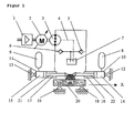
- a drive according to the invention is used to to drive a machine axis consisting of one Load mass 20, which on the guides 18, 19 in the direction X is movable.
- the pump 3 is hydraulic with two Chambers 16, 17 of the cylinders 10, 11 connected.
- the two Cylinder rods 21, 22 of the cylinders 10, 11 are over the Load 20 mechanically coupled.
- the arrangement looks like a only cylinder in the closed circuit from the pump 3 is supplied with pressure oil.
- the bearings 12, 13 symbolize a firm mechanical connection with the machine.
- the leakage line 4 of the pump 3 leads a small oil flow into the tank 7. About the The oil comes back into both check valves 5,6 the drive circuit as soon as the pressure in one of the two Pump connections drop below the pressure level in tank 7.
- the Tank 7 can be used as a tank, separate pump group or other pressure source may be formed.
- the components are now designed so that the restoring forces have the desired speed profile ideally support the drive.
- the Preload pressures in the pressure accumulators 8, 9 are selected to be very small or neglected, there is practically a pure one Pump drive in a closed circuit.
- the spring forces of the pressure accumulators larger and support with appropriate design the desired, cyclical movement of the load mass.
- Engine 2, Pump 3, cylinder rods 21, 22 and load mass 20 must then no longer exclusively from the electro-magnetic Forces of the motor 2 are accelerated, but will be supported by the pressure forces of the pressure accumulator.
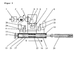
- Figure 2 shows a particularly advantageous embodiment an inventive device for driving a Punching or embossing machine.
- the two cylinders were 10.11 united in a block 22.
- As an additional element introduced two valves 24,25.
- the cylinder chambers 14, 15 can by means of the valve magnets 23, 26 from the pressure accumulators 8.9 can be switched to tank 7.
- valves 24, 25 can be switched on and off by the Position of the piston rod can be controlled, the valves 24, 25 can also be integrated in the cylinder.
- the feed and Switching off then always takes place in the same place.
- the Drive behaves like a trampoline jumper on a spring jumps and is thrown back by this in consequently an approximately force-free, ballistic To make movement. According to the forces of the Electric motor 2 only used the intrinsic shape of the movement to influence the resulting movement Corresponds to the requirements of the work process.
- the pressure accumulator 8,9,27,28 can also be used for other hydraulic Secondary functions are used such as small ones Auxiliary pistons or valve pilot controls. It doesn't need to necessary to deal with 4 independent accumulators, the function of the oscillator can also be done with only one pressure accumulator be guaranteed.
- the punching tool consists of the parts punch 20, Press plate 29, die 30, ejector 31 and the one to be machined Metal strips 32. That in this application example indicated tool is passive, i.e. the movement of Press plate 29 and ejector 31 are hydraulic Spring forces of the pressure accumulator 27, 28 and mechanical movement limitation defined, without own motion control. Of course, other hydraulic ones can also be used in the tool Functions with valve control can be integrated.
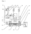
- Figure 3 shows a further advantageous embodiment of a device according to the invention.
- the machine axis is here formed as an injection unit 20 of an injection molding machine and must have very high forces and powers in the X direction apply to the plastic under high pressure in the Press tool of a machine not drawn. To the injection process, the injection unit must be practical disappearing forces back to the starting position become.
- This asymmetrical task also corresponds to an asymmetrical one Design of the device according to the invention. If you choose a relatively high pressure level in the accumulator 9 and a relatively large cross section of the cylinder chamber 15, the force range of the device shifts towards positive forces in direction X at accordingly reduced forces in the opposite direction.
- the memory 8 can be omitted. at suitable design of the device will be the full moment of the engine 2 needed to move the piston rod 21 to the starting position to bring before or in the injection process Hold position. During the subsequent injection process work engine 2, pump 3 and accumulator 9 in the same Direction. In this way, the benefits of Pressure accumulator and pump.
- the valves 23, 24 represent another special element a device according to the invention.
- the valve magnets 25,26 switch the valves 23,24 and thus connect the Pressure accumulator 8.9, each with a pressure line from the pump.
- the preload pressure in the pressure accumulators is 8.9 variable.
- the supply of the valves can also by another, independent pressure source.
- the neutral position can be set. In a neutral location is the position of the piston rod 21 at which the compressive forces neutralize the memory 8.9, understand.
- FIG. 4 shows a somewhat modified form of an inventive one Device for driving a toggle mechanism 20. Only a single cylinder 10 is used.
- a hydraulic oscillator can also be used in this way with those described in the previous sections Realize properties.
- the pump delivers oil from the Cylinder chamber 16 in the pressure accumulator 8, the increases Pressure in the memory 8 and the piston rod 17 moves in direction X, driven by the pressure forces in the chamber 14. This reduces these pressure forces.
- the whole device again acts like a spring-mass oscillator, which is cyclical even without external forces Can perform movement (natural vibration).
- the device in FIG. 4 consists of the second pump group consisting of motor 13, pump 11 and pressure relief valve 15. This unit creates a constant pressure on the Check valves 5.6 and ensures that the pressure in the Pressure accumulators 8.9 do not have a preset minimum value below.
- the pump group also replaces the leak oil Pump 3, which through the leak oil line 4 in the tank 7th arrives.
- the machine axis 20 is designed as a swivel joint.
- the device according to the invention corresponds here largely the device in Figure 2.
- the pressure accumulator 8.9 in Figure 2 are, however, by a single pressure accumulator 8 replaced, which supplies both valves 24.25 with pressure oil.
- FIG Position measuring system 34 was shown in FIG Position measuring system 34 and a control computer 31 shown. These elements were shown in Figures 1 to 4 for the sake of Clarity not shown, but allow one more precise control of the device.
- the path measuring system 34 can integrated especially in the cylinder (s) his. In addition to pressure and position, temporal Derivatives of these quantities are recorded.
- the signals from displacement measuring system 34 and pressure sensors 28, 29, 33 are available to the control computer 31, which the Converter 1 in accordance with a control algorithm such as controlled by a state control.
- the target movement of the Device Xset 32 is controlled by a parent Machine control generated. This enables the regulation the position as well as the force, which of the inventive Device exerted on the machine axis 20 becomes.
- the control computer 31 can also in the converter or in the higher-level machine control system. In in many applications, it is sufficient to print in just one Cylinder chamber 14,15,16,17 to capture.
- the use of the device is very versatile. So can they e.g. to drive one axis of a crane, one Press, a forming press, a bending press, scissors, a straightening machine, a test machine, a lifting platform, a punching machine, an injection molding machine, one Die casting machine or another machine used become.
- the device or parts thereof is also for other purposes and can only be used temporarily For the purposes of the invention.
Landscapes
- Engineering & Computer Science (AREA)
- Mechanical Engineering (AREA)
- Physics & Mathematics (AREA)
- Fluid Mechanics (AREA)
- General Engineering & Computer Science (AREA)
- Chemical & Material Sciences (AREA)
- Analytical Chemistry (AREA)
- Fluid-Pressure Circuits (AREA)
Abstract
Description
- Fig. 1
- eine schematische Darstellung einer erfindungsgemäßen Vorrichtung zum Antrieb einer Lastmasse;
- Fig. 2
- eine schematische Darstellung einer erfindungsgemäßen Vorrichtung zum Antrieb einer Stanz- oder Prägmaschine;
- Fig. 3
- eine schematische Darstellung einer erfindungsgemäßen Vorrichtung zum Antrieb einer Einspritzeinheit einer Spritzgiessmaschine;
- Fig. 4
- eine schematische Darstellung einer erfindungsgemäßen Vorrichtung zum Antrieb eines Kniehebelmechanismus; und
- Fig. 5
- eine schematische Darstellung einer erfindungsgemäßen Vorrichtung zum Antrieb eines Drehgelenks.
Claims (11)
- Vorrichtung zum kontrollierten Antrieb einer Maschinenachse (20), bestehend aus einem hydraulischen Aktuator (10, 11), einer hydraulischen Pumpe (3), die hydraulisch mit dem Aktuator (10, 11) verbunden ist und einem drehzahlvariablen Elektromotor (2), der die hydraulische Pumpe (3) antreibt, dadurch gekennzeichnet, daß mindestens ein Energiespeicher (8, 9) mit Potentialkräften auf den hydraulischen Aktuator (10, 11) oder die Maschinenachse (20) wirkt und daß der Energiespeicher (8, 9) durch eine Bewegung der Maschinenachse (20) gefüllt oder entladen wird.
- Vorrichtung nach Anspruch 1, dadurch gekennzeichnet, daß die hydraulische Pumpe (3) im geschlossenen Kreis mit dem Aktuator (10, 11) verbunden ist.
- Vorrichtung nach Anspruch 1, dadurch gekennzeichnet, daß mindestens ein weiterer Energiespeicher (8) mit einem zweiten Anschluss der Pumpe (3) verbunden ist und daß die Energiespeicher (8, 9) durch eine Bewegung der Maschinenachse gefüllt oder entladen werden.
- Vorrichtung nach Anspruch 3, dadurch gekennzeichnet, daß die hydraulische Pumpe (3) mit einer hydraulischen Leitung mit dem hydraulischen Aktuator (10) verbunden ist.
- Vorrichtung nach einem der Ansprüche 1 bis 4, dadurch gekennzeichnet, daß der oder die Energiespeicher durch mindestens ein Ventil oder eine Kupplung vom hydraulischen Aktuator oder von der Maschine getrennt werden können.
- Vorrichtung nach einem der Ansprüche 1 bis 5, dadurch gekennzeichnet, daß der oder die Energiespeicher über ein zusätzliches Ventil oder eine zusätzliche Vorrichtung aufgeladen oder entladen werden können.
- Vorrichtung nach einem der Ansprüch1 1 bis 6, dadurch gekennzeichnet, daß die hydraulischen Aktuatoren als hydraulische Zylinder, hydraulische Zylinder mit durchgehender Kolbenstange, Schwenkkolben, hydraulische Pumpen oder hydraulische Motoren ausgebildet sind.
- Vorrichtung nach einem der Ansprüche 1 bis 7, dadurch gekennzeichnet, daß die Vorrichtung zum Antrieb jeweils einer Achse eines Krans, einer Presse, einer Umformpresse, einer Biegepresse, einer Schere, einer Streckrichtmaschine, einer Testmaschine, einer Hebebühne, einer Stanzmaschine, einer Spritzgiessmaschine, oder einer Druckgiessmaschine eingesetzt wird.
- Vorrichtung nach einem der Ansprüche 1 bis 8, dadurch gekennzeichnet, daß die Vorrichtung Sensoren aufweist, die Drücke, Positionen oder deren zeitliche Ableitungen messen und einer elektronischen Steuerung übermitteln.
- Vorrichtung nach einem der Ansprüche 1 bis 9, dadurch gekennzeichnet, daß der Elektromotor als permanent erregter Synchronmotor, als vektorgeregelter Asynchronmotor, als Gleichstrommotor, als bürstenloser DC-Motor oder geschalteter Reluctance-Motor ausgebildet ist.
- Vorrichtung nach einem der Ansprüche 1 bis 10, dadurch gekennzeichnet, daß eine innen- oder aussenverzahnte, kompensierte oder nichtkompensierte Zahnradpumpe, eine konstante oder verstellbare Axial- oder Radialkolbenpumpe, eine konstante oder verstellbare Flügelzellenpumpe, eine Schraubenpumpe oder eine andere hydrostatische Verdrängungseinheit eingesetzt wird.
Applications Claiming Priority (2)
| Application Number | Priority Date | Filing Date | Title |
|---|---|---|---|
| CH2842001 | 2001-02-17 | ||
| CH2842001 | 2001-02-17 |
Publications (3)
| Publication Number | Publication Date |
|---|---|
| EP1233191A2 true EP1233191A2 (de) | 2002-08-21 |
| EP1233191A3 EP1233191A3 (de) | 2004-01-02 |
| EP1233191B1 EP1233191B1 (de) | 2005-11-09 |
Family
ID=4484432
Family Applications (1)
| Application Number | Title | Priority Date | Filing Date |
|---|---|---|---|
| EP01128622A Expired - Lifetime EP1233191B1 (de) | 2001-02-17 | 2001-11-30 | Hydraulischer Oszillator als Antrieb von Maschinen |
Country Status (5)
| Country | Link |
|---|---|
| US (1) | US6647719B2 (de) |
| EP (1) | EP1233191B1 (de) |
| JP (1) | JP2002257102A (de) |
| AT (1) | ATE309471T1 (de) |
| DE (1) | DE50107980D1 (de) |
Cited By (14)
| Publication number | Priority date | Publication date | Assignee | Title |
|---|---|---|---|---|
| DE10349758B3 (de) * | 2003-10-24 | 2005-06-09 | Schuler Pressen Gmbh & Co. Kg | Antriebseinrichtung |
| WO2007001694A1 (en) | 2005-06-24 | 2007-01-04 | Exxonmobil Chemical Patents Inc. | Functionalized propylene copolymer adheside composition |
| US7951732B2 (en) | 2007-01-26 | 2011-05-31 | Exxonmobil Chemical Patents Inc. | Elastomeric laminates for consumer products |
| WO2011087695A2 (en) | 2009-12-23 | 2011-07-21 | Invista Technologies S.A R.L. | Polyolefin elastic fiber |
| WO2011087692A2 (en) | 2009-12-23 | 2011-07-21 | Invista Technologies S.A R.L. | Stretch articles including polyolefin elastic fiber |
| WO2011087693A2 (en) | 2009-12-23 | 2011-07-21 | Invista Technologies S.A R.1. | Elastic fiber containing an anti-tack additive |
| US8236878B2 (en) | 2007-09-07 | 2012-08-07 | Exxonmobil Chemical Patents Inc. | Composition and manufacture thereof |
| WO2013055496A1 (en) | 2011-10-14 | 2013-04-18 | Exxonmobil Chemical Patents Inc. | Polyolefin-based crosslinked compositions and methods of making them |
| WO2013096532A1 (en) | 2011-12-22 | 2013-06-27 | Exxonmobil Research And Engineering Company | Method for improving engine fuel efficiency |
| US8609772B2 (en) | 2007-10-23 | 2013-12-17 | Exxonmobil Chemical Patents Inc. | Elastic films having improved mechanical and elastic properties and methods for making the same |
| WO2016069089A1 (en) | 2014-10-29 | 2016-05-06 | Exxonmobil Chemical Patents Inc. | Polyolefin adhesive compositions for elastic applications |
| EP3214158A1 (de) | 2008-08-08 | 2017-09-06 | ExxonMobil Chemical Patents Inc. | Verbesserte olefincopolymerzusammensetzungen zur viskositätsmodifikation von motoröl |
| US10041190B2 (en) | 2009-12-23 | 2018-08-07 | Invista North America S.A.R.L. | Fabric including polyolefin elastic fiber |
| WO2019156802A1 (en) | 2018-02-12 | 2019-08-15 | Exxonmobil Chemical Patents Inc. | Metallocene catalyst feed system for solution polymerization process |
Families Citing this family (23)
| Publication number | Priority date | Publication date | Assignee | Title |
|---|---|---|---|---|
| US7176648B2 (en) * | 2004-05-18 | 2007-02-13 | Husky Injection Molding Systems Ltd. | Energy management apparatus and method for injection molding systems |
| WO2006002205A2 (en) | 2004-06-21 | 2006-01-05 | Cole Jeffrey E | Truck assembly for a skateboard, wheeled platform, or vehicle |
| US7232139B2 (en) | 2004-06-21 | 2007-06-19 | Cole Jeffrey E | Truck assembly for a skateboard, wheeled platform, or vehicle |
| US7216876B2 (en) | 2004-06-21 | 2007-05-15 | Cole Jeffrey E | Occupant-propelled fluid powered rotary device, truck, wheeled platform, or vehicle |
| US7040638B2 (en) | 2004-06-21 | 2006-05-09 | Jeffrey Eaton Cole | Occupant-propelled fluid powered rotary device, truck, wheeled platform, or vehicle |
| JP4115430B2 (ja) * | 2004-07-09 | 2008-07-09 | 日精樹脂工業株式会社 | 生産機械の駆動方法 |
| US7635136B2 (en) | 2005-06-21 | 2009-12-22 | Jeffrey E. Cole | Truck assembly for a skateboard, wheeled platform, or vehicle |
| JP2009513882A (ja) * | 2005-10-31 | 2009-04-02 | チャプドライヴ・アクティーゼルスカブ | タービン駆動式発電システム及びその制御方法 |
| US7191593B1 (en) * | 2005-11-28 | 2007-03-20 | Northrop Grumman Corporation | Electro-hydraulic actuator system |
| WO2008016518A2 (en) * | 2006-08-02 | 2008-02-07 | Exxonmobil Chemical Patents Inc. | Propylene-based polymer article |
| US20080155975A1 (en) * | 2006-12-28 | 2008-07-03 | Caterpillar Inc. | Hydraulic system with energy recovery |
| US8241753B2 (en) * | 2007-06-04 | 2012-08-14 | Exxonmobil Chemical Patents Inc. | Composite thermoplastic elastomer structures with high adhesion performance and uses for the same |
| US8706192B2 (en) * | 2008-02-16 | 2014-04-22 | Geng Li | Magnetic resonance elastograph system with hydraulic driver |
| WO2009158100A2 (en) * | 2008-06-27 | 2009-12-30 | Exxonmobil Chemical Patents Inc. | High shrinkage propylene-based films |
| US8186154B2 (en) * | 2008-10-31 | 2012-05-29 | Caterpillar Inc. | Rotary flow control valve with energy recovery |
| GB2473054A (en) * | 2009-08-28 | 2011-03-02 | Gm Global Tech Operations Inc | Synchronizer actuator having a piston that delimits three chambers |
| US9151018B2 (en) * | 2011-09-30 | 2015-10-06 | Caterpillar Inc. | Closed-loop hydraulic system having energy recovery |
| DE102012009669B3 (de) | 2012-05-03 | 2013-08-14 | Hydac Technology Gmbh | Vorrichtung zur Energieeinsparung bei hydraulisch betätigbaren Arbeitsgerätschaften |
| KR102288888B1 (ko) * | 2017-06-09 | 2021-08-12 | 현대자동차주식회사 | 주행 모드 변경이 가능한 소형 모빌리티 |
| DE102018128318A1 (de) * | 2018-11-13 | 2020-05-14 | Moog Luxembourg S.à.r.l. | Elektrohydrostatisches Aktuatorsystem |
| CN112343955A (zh) * | 2020-10-29 | 2021-02-09 | 饶英俊 | 一种振激式单杆双室双活塞漏油报警减震器 |
| DE102022127671A1 (de) * | 2022-10-20 | 2024-04-25 | Liebherr-Components Kirchdorf GmbH | Aktuatorsystem mit oszillierender Hubbewegung |
| CN119038432B (zh) * | 2024-10-14 | 2025-10-03 | 中国船舶集团华南船机有限公司 | 一种多个绞盘之间的联动方法 |
Citations (1)
| Publication number | Priority date | Publication date | Assignee | Title |
|---|---|---|---|---|
| WO1997005387A1 (de) | 1995-05-16 | 1997-02-13 | Truninger Ag | Vorrichtung mit wenigstens einer hydraulischen achse |
Family Cites Families (9)
| Publication number | Priority date | Publication date | Assignee | Title |
|---|---|---|---|---|
| US2699649A (en) * | 1949-07-15 | 1955-01-18 | Kirwan Y Messick | Hydraulic system for power shears and like machines |
| US3855791A (en) * | 1973-08-24 | 1974-12-24 | M Quinto | Reversible motor hydraulic control system |
| US3971215A (en) * | 1974-06-06 | 1976-07-27 | Marion Power Shovel Company, Inc. | Power shovel and crowd system therefor |
| DE2448723A1 (de) * | 1974-10-12 | 1976-04-22 | Maschf Augsburg Nuernberg Ag | Wandleraggregat fuer verbrennungsmotoren |
| DE3705642A1 (de) * | 1986-07-02 | 1988-01-14 | Man Nutzfahrzeuge Gmbh | Energiespeicher- und abgabeeinrichtung |
| US4760697A (en) * | 1986-08-13 | 1988-08-02 | National Research Council Of Canada | Mechanical power regeneration system |
| US5428958A (en) * | 1987-05-19 | 1995-07-04 | Flutron Ab | Electrohydraulic control system |
| JPH0639317B2 (ja) * | 1989-09-09 | 1994-05-25 | 株式会社神戸製鋼所 | 移動式クレーンの変位抑制機構 |
| US5916139A (en) * | 1997-09-16 | 1999-06-29 | My-D Han-D Mfg. Co. Inc. | Hydraulic system and pump |
-
2001
- 2001-11-30 AT AT01128622T patent/ATE309471T1/de not_active IP Right Cessation
- 2001-11-30 DE DE50107980T patent/DE50107980D1/de not_active Expired - Lifetime
- 2001-11-30 EP EP01128622A patent/EP1233191B1/de not_active Expired - Lifetime
-
2002
- 2002-01-24 US US10/056,138 patent/US6647719B2/en not_active Expired - Fee Related
- 2002-01-29 JP JP2002020276A patent/JP2002257102A/ja active Pending
Patent Citations (1)
| Publication number | Priority date | Publication date | Assignee | Title |
|---|---|---|---|---|
| WO1997005387A1 (de) | 1995-05-16 | 1997-02-13 | Truninger Ag | Vorrichtung mit wenigstens einer hydraulischen achse |
Cited By (15)
| Publication number | Priority date | Publication date | Assignee | Title |
|---|---|---|---|---|
| DE10349758B3 (de) * | 2003-10-24 | 2005-06-09 | Schuler Pressen Gmbh & Co. Kg | Antriebseinrichtung |
| WO2007001694A1 (en) | 2005-06-24 | 2007-01-04 | Exxonmobil Chemical Patents Inc. | Functionalized propylene copolymer adheside composition |
| US7951732B2 (en) | 2007-01-26 | 2011-05-31 | Exxonmobil Chemical Patents Inc. | Elastomeric laminates for consumer products |
| US8236878B2 (en) | 2007-09-07 | 2012-08-07 | Exxonmobil Chemical Patents Inc. | Composition and manufacture thereof |
| US8609772B2 (en) | 2007-10-23 | 2013-12-17 | Exxonmobil Chemical Patents Inc. | Elastic films having improved mechanical and elastic properties and methods for making the same |
| EP3214158A1 (de) | 2008-08-08 | 2017-09-06 | ExxonMobil Chemical Patents Inc. | Verbesserte olefincopolymerzusammensetzungen zur viskositätsmodifikation von motoröl |
| WO2011087693A2 (en) | 2009-12-23 | 2011-07-21 | Invista Technologies S.A R.1. | Elastic fiber containing an anti-tack additive |
| WO2011087692A2 (en) | 2009-12-23 | 2011-07-21 | Invista Technologies S.A R.L. | Stretch articles including polyolefin elastic fiber |
| WO2011087695A2 (en) | 2009-12-23 | 2011-07-21 | Invista Technologies S.A R.L. | Polyolefin elastic fiber |
| US10039855B2 (en) | 2009-12-23 | 2018-08-07 | Invista North America S.A.R.L. | Elastic fiber containing an anti-tack additive |
| US10041190B2 (en) | 2009-12-23 | 2018-08-07 | Invista North America S.A.R.L. | Fabric including polyolefin elastic fiber |
| WO2013055496A1 (en) | 2011-10-14 | 2013-04-18 | Exxonmobil Chemical Patents Inc. | Polyolefin-based crosslinked compositions and methods of making them |
| WO2013096532A1 (en) | 2011-12-22 | 2013-06-27 | Exxonmobil Research And Engineering Company | Method for improving engine fuel efficiency |
| WO2016069089A1 (en) | 2014-10-29 | 2016-05-06 | Exxonmobil Chemical Patents Inc. | Polyolefin adhesive compositions for elastic applications |
| WO2019156802A1 (en) | 2018-02-12 | 2019-08-15 | Exxonmobil Chemical Patents Inc. | Metallocene catalyst feed system for solution polymerization process |
Also Published As
| Publication number | Publication date |
|---|---|
| DE50107980D1 (de) | 2005-12-15 |
| US20020112476A1 (en) | 2002-08-22 |
| JP2002257102A (ja) | 2002-09-11 |
| ATE309471T1 (de) | 2005-11-15 |
| EP1233191B1 (de) | 2005-11-09 |
| EP1233191A3 (de) | 2004-01-02 |
| US6647719B2 (en) | 2003-11-18 |
Similar Documents
| Publication | Publication Date | Title |
|---|---|---|
| EP1233191B1 (de) | Hydraulischer Oszillator als Antrieb von Maschinen | |
| EP0782671B1 (de) | Vorrichtung zum kontrollierten antrieb wenigstens einer hydraulischen achse | |
| EP0873475B1 (de) | Verlustarmer antrieb für mehrere hydraulische aktuatoren | |
| DE102011000473B4 (de) | Pressmaschine und Verfahren zum Pressen von Werkstücken | |
| EP0403041B2 (de) | Spritzgiessmaschine mit hydraulischen Verbrauchern | |
| EP2676036B1 (de) | Druckspeicherlose hydraulische antriebsanordnung für und mit einem verbraucher, insbesondere für pressen sowie verfahren zum betreiben einer solchen druckspeicherlosen hydraulischen antriebsanordnung | |
| EP3077674B1 (de) | Hydraulische anordnung | |
| EP2420681B1 (de) | Hydraulischer Linearantrieb | |
| DE102006058630B4 (de) | Elektrohydraulische Pressenhaupt- oder Nebenantriebseinrichtung, insbesondere elektrohydraulischer Ziehkissenantrieb | |
| EP1288507B1 (de) | Verlustarmer Antrieb für einen hydraulischen Aktuator | |
| WO2009026893A1 (de) | Antriebssystem für hydraulische pressen | |
| DE102005038583B4 (de) | Pressen-Antriebsmodul und Verfahren zur Bereitstellung einer Pressenbaureihe | |
| EP0561185A1 (de) | Hydraulische Schiebersteuerung für Arbeitszylinder mit ungleichen Kolbengeschwindigkeiten | |
| DE102005012876A1 (de) | Verfahren und Vorrichtung zur Steuerung und Regelung von servo-elektrischen Ziehkissen | |
| EP1086802B1 (de) | Presse mit Exzenterkurbelbetrieb für Oberstempeleinheit und Betriebsverfahren | |
| EP0618025B1 (de) | Einpressaggregat | |
| EP1355775B1 (de) | Regelverfahren für die hydraulische unterstützung eines elektrischen antriebs | |
| DE102018203367A1 (de) | Hydrostatischer Linearantrieb | |
| DE102015218578A1 (de) | Hydrostatische verstelleinrichtung mit verminderter hysterese | |
| DE102006046694A1 (de) | Antriebssystem mit Hohlwellenmotor und Getriebe | |
| EP3774316B1 (de) | Pressenantrieb mit energierückgewinnung | |
| EP1754595B1 (de) | Pressen-Antriebsmodul und Verfahren zur Bereitstellung einer Pressenbaureihe | |
| DE4410719A1 (de) | Elektrohydraulisch verstellbare Pumpe | |
| DE102004030678A1 (de) | Ziehkissen-Vorrichtung mit Hybrid-Antrieb | |
| DE10219581B4 (de) | Antrieb für einen Pressenstößel |
Legal Events
| Date | Code | Title | Description |
|---|---|---|---|
| PUAI | Public reference made under article 153(3) epc to a published international application that has entered the european phase |
Free format text: ORIGINAL CODE: 0009012 |
|
| AK | Designated contracting states |
Kind code of ref document: A2 Designated state(s): AT BE CH CY DE DK ES FI FR GB GR IE IT LI LU MC NL PT SE TR |
|
| AX | Request for extension of the european patent |
Free format text: AL;LT;LV;MK;RO;SI |
|
| PUAL | Search report despatched |
Free format text: ORIGINAL CODE: 0009013 |
|
| AK | Designated contracting states |
Kind code of ref document: A3 Designated state(s): AT BE CH CY DE DK ES FI FR GB GR IE IT LI LU MC NL PT SE TR |
|
| AX | Request for extension of the european patent |
Extension state: AL LT LV MK RO SI |
|
| 17P | Request for examination filed |
Effective date: 20040528 |
|
| 17Q | First examination report despatched |
Effective date: 20040728 |
|
| AKX | Designation fees paid |
Designated state(s): AT BE CH CY DE DK ES FI FR GB GR IE IT LI LU MC NL PT SE TR |
|
| GRAP | Despatch of communication of intention to grant a patent |
Free format text: ORIGINAL CODE: EPIDOSNIGR1 |
|
| GRAS | Grant fee paid |
Free format text: ORIGINAL CODE: EPIDOSNIGR3 |
|
| GRAA | (expected) grant |
Free format text: ORIGINAL CODE: 0009210 |
|
| AK | Designated contracting states |
Kind code of ref document: B1 Designated state(s): AT BE CH CY DE DK ES FI FR GB GR IE IT LI LU MC NL PT SE TR |
|
| PG25 | Lapsed in a contracting state [announced via postgrant information from national office to epo] |
Ref country code: FI Free format text: LAPSE BECAUSE OF FAILURE TO SUBMIT A TRANSLATION OF THE DESCRIPTION OR TO PAY THE FEE WITHIN THE PRESCRIBED TIME-LIMIT Effective date: 20051109 Ref country code: TR Free format text: LAPSE BECAUSE OF FAILURE TO SUBMIT A TRANSLATION OF THE DESCRIPTION OR TO PAY THE FEE WITHIN THE PRESCRIBED TIME-LIMIT Effective date: 20051109 Ref country code: NL Free format text: LAPSE BECAUSE OF FAILURE TO SUBMIT A TRANSLATION OF THE DESCRIPTION OR TO PAY THE FEE WITHIN THE PRESCRIBED TIME-LIMIT Effective date: 20051109 Ref country code: IT Free format text: LAPSE BECAUSE OF FAILURE TO SUBMIT A TRANSLATION OF THE DESCRIPTION OR TO PAY THE FEE WITHIN THE PRESCRIBED TIME-LIMIT;WARNING: LAPSES OF ITALIAN PATENTS WITH EFFECTIVE DATE BEFORE 2007 MAY HAVE OCCURRED AT ANY TIME BEFORE 2007. THE CORRECT EFFECTIVE DATE MAY BE DIFFERENT FROM THE ONE RECORDED. Effective date: 20051109 |
|
| REG | Reference to a national code |
Ref country code: GB Ref legal event code: FG4D Free format text: NOT ENGLISH |
|
| REG | Reference to a national code |
Ref country code: CH Ref legal event code: NV Representative=s name: E. BLUM & CO. PATENTANWAELTE Ref country code: CH Ref legal event code: EP |
|
| PG25 | Lapsed in a contracting state [announced via postgrant information from national office to epo] |
Ref country code: MC Free format text: LAPSE BECAUSE OF NON-PAYMENT OF DUE FEES Effective date: 20051130 Ref country code: CY Free format text: LAPSE BECAUSE OF FAILURE TO SUBMIT A TRANSLATION OF THE DESCRIPTION OR TO PAY THE FEE WITHIN THE PRESCRIBED TIME-LIMIT Effective date: 20051130 |
|
| REG | Reference to a national code |
Ref country code: IE Ref legal event code: FG4D Free format text: LANGUAGE OF EP DOCUMENT: GERMAN |
|
| REF | Corresponds to: |
Ref document number: 50107980 Country of ref document: DE Date of ref document: 20051215 Kind code of ref document: P |
|
| PG25 | Lapsed in a contracting state [announced via postgrant information from national office to epo] |
Ref country code: DK Free format text: LAPSE BECAUSE OF FAILURE TO SUBMIT A TRANSLATION OF THE DESCRIPTION OR TO PAY THE FEE WITHIN THE PRESCRIBED TIME-LIMIT Effective date: 20060209 Ref country code: SE Free format text: LAPSE BECAUSE OF FAILURE TO SUBMIT A TRANSLATION OF THE DESCRIPTION OR TO PAY THE FEE WITHIN THE PRESCRIBED TIME-LIMIT Effective date: 20060209 Ref country code: GR Free format text: LAPSE BECAUSE OF FAILURE TO SUBMIT A TRANSLATION OF THE DESCRIPTION OR TO PAY THE FEE WITHIN THE PRESCRIBED TIME-LIMIT Effective date: 20060209 |
|
| PG25 | Lapsed in a contracting state [announced via postgrant information from national office to epo] |
Ref country code: ES Free format text: LAPSE BECAUSE OF FAILURE TO SUBMIT A TRANSLATION OF THE DESCRIPTION OR TO PAY THE FEE WITHIN THE PRESCRIBED TIME-LIMIT Effective date: 20060220 |
|
| GBT | Gb: translation of ep patent filed (gb section 77(6)(a)/1977) |
Effective date: 20060214 |
|
| PG25 | Lapsed in a contracting state [announced via postgrant information from national office to epo] |
Ref country code: PT Free format text: LAPSE BECAUSE OF FAILURE TO SUBMIT A TRANSLATION OF THE DESCRIPTION OR TO PAY THE FEE WITHIN THE PRESCRIBED TIME-LIMIT Effective date: 20060410 |
|
| NLV1 | Nl: lapsed or annulled due to failure to fulfill the requirements of art. 29p and 29m of the patents act | ||
| ET | Fr: translation filed | ||
| PLBE | No opposition filed within time limit |
Free format text: ORIGINAL CODE: 0009261 |
|
| STAA | Information on the status of an ep patent application or granted ep patent |
Free format text: STATUS: NO OPPOSITION FILED WITHIN TIME LIMIT |
|
| 26N | No opposition filed |
Effective date: 20060810 |
|
| REG | Reference to a national code |
Ref country code: CH Ref legal event code: PFA Owner name: GLOBEMAG L.P. Free format text: GLOBEMAG L.P.#40 MELVILLE STREET#EDINBURGH EH3 7TW (GB) -TRANSFER TO- GLOBEMAG L.P.#40 MELVILLE STREET#EDINBURGH EH3 7TW (GB) |
|
| PGFP | Annual fee paid to national office [announced via postgrant information from national office to epo] |
Ref country code: IE Payment date: 20071122 Year of fee payment: 7 |
|
| REG | Reference to a national code |
Ref country code: IE Ref legal event code: MM4A |
|
| PG25 | Lapsed in a contracting state [announced via postgrant information from national office to epo] |
Ref country code: IE Free format text: LAPSE BECAUSE OF NON-PAYMENT OF DUE FEES Effective date: 20081201 |
|
| PGFP | Annual fee paid to national office [announced via postgrant information from national office to epo] |
Ref country code: AT Payment date: 20091113 Year of fee payment: 9 Ref country code: CH Payment date: 20091124 Year of fee payment: 9 Ref country code: LU Payment date: 20091120 Year of fee payment: 9 |
|
| PGFP | Annual fee paid to national office [announced via postgrant information from national office to epo] |
Ref country code: FR Payment date: 20091201 Year of fee payment: 9 Ref country code: GB Payment date: 20091119 Year of fee payment: 9 |
|
| PGFP | Annual fee paid to national office [announced via postgrant information from national office to epo] |
Ref country code: BE Payment date: 20091224 Year of fee payment: 9 Ref country code: DE Payment date: 20091228 Year of fee payment: 9 |
|
| BERE | Be: lapsed |
Owner name: *GLOBEMAG L.P. Effective date: 20101130 |
|
| REG | Reference to a national code |
Ref country code: CH Ref legal event code: PL |
|
| GBPC | Gb: european patent ceased through non-payment of renewal fee |
Effective date: 20101130 |
|
| PG25 | Lapsed in a contracting state [announced via postgrant information from national office to epo] |
Ref country code: LI Free format text: LAPSE BECAUSE OF NON-PAYMENT OF DUE FEES Effective date: 20101130 Ref country code: CH Free format text: LAPSE BECAUSE OF NON-PAYMENT OF DUE FEES Effective date: 20101130 |
|
| REG | Reference to a national code |
Ref country code: FR Ref legal event code: ST Effective date: 20110801 |
|
| PG25 | Lapsed in a contracting state [announced via postgrant information from national office to epo] |
Ref country code: AT Free format text: LAPSE BECAUSE OF NON-PAYMENT OF DUE FEES Effective date: 20101130 Ref country code: BE Free format text: LAPSE BECAUSE OF NON-PAYMENT OF DUE FEES Effective date: 20101130 |
|
| REG | Reference to a national code |
Ref country code: DE Ref legal event code: R119 Ref document number: 50107980 Country of ref document: DE Effective date: 20110601 Ref country code: DE Ref legal event code: R119 Ref document number: 50107980 Country of ref document: DE Effective date: 20110531 |
|
| PG25 | Lapsed in a contracting state [announced via postgrant information from national office to epo] |
Ref country code: FR Free format text: LAPSE BECAUSE OF NON-PAYMENT OF DUE FEES Effective date: 20101130 |
|
| PG25 | Lapsed in a contracting state [announced via postgrant information from national office to epo] |
Ref country code: GB Free format text: LAPSE BECAUSE OF NON-PAYMENT OF DUE FEES Effective date: 20101130 |
|
| PG25 | Lapsed in a contracting state [announced via postgrant information from national office to epo] |
Ref country code: LU Free format text: LAPSE BECAUSE OF NON-PAYMENT OF DUE FEES Effective date: 20101130 |
|
| PG25 | Lapsed in a contracting state [announced via postgrant information from national office to epo] |
Ref country code: DE Free format text: LAPSE BECAUSE OF NON-PAYMENT OF DUE FEES Effective date: 20110531 |