EP1232804A2 - Method for removing sludge in crude oil tank and recovering oil therefrom - Google Patents
Method for removing sludge in crude oil tank and recovering oil therefrom Download PDFInfo
- Publication number
- EP1232804A2 EP1232804A2 EP02003720A EP02003720A EP1232804A2 EP 1232804 A2 EP1232804 A2 EP 1232804A2 EP 02003720 A EP02003720 A EP 02003720A EP 02003720 A EP02003720 A EP 02003720A EP 1232804 A2 EP1232804 A2 EP 1232804A2
- Authority
- EP
- European Patent Office
- Prior art keywords
- oil
- sludge
- storage tank
- thermal oil
- thermal
- Prior art date
- Legal status (The legal status is an assumption and is not a legal conclusion. Google has not performed a legal analysis and makes no representation as to the accuracy of the status listed.)
- Granted
Links
Images


Classifications
-
- B—PERFORMING OPERATIONS; TRANSPORTING
- B01—PHYSICAL OR CHEMICAL PROCESSES OR APPARATUS IN GENERAL
- B01D—SEPARATION
- B01D17/00—Separation of liquids, not provided for elsewhere, e.g. by thermal diffusion
-
- C—CHEMISTRY; METALLURGY
- C10—PETROLEUM, GAS OR COKE INDUSTRIES; TECHNICAL GASES CONTAINING CARBON MONOXIDE; FUELS; LUBRICANTS; PEAT
- C10G—CRACKING HYDROCARBON OILS; PRODUCTION OF LIQUID HYDROCARBON MIXTURES, e.g. BY DESTRUCTIVE HYDROGENATION, OLIGOMERISATION, POLYMERISATION; RECOVERY OF HYDROCARBON OILS FROM OIL-SHALE, OIL-SAND, OR GASES; REFINING MIXTURES MAINLY CONSISTING OF HYDROCARBONS; REFORMING OF NAPHTHA; MINERAL WAXES
- C10G31/00—Refining of hydrocarbon oils, in the absence of hydrogen, by methods not otherwise provided for
-
- B—PERFORMING OPERATIONS; TRANSPORTING
- B08—CLEANING
- B08B—CLEANING IN GENERAL; PREVENTION OF FOULING IN GENERAL
- B08B9/00—Cleaning hollow articles by methods or apparatus specially adapted thereto
- B08B9/08—Cleaning containers, e.g. tanks
- B08B9/093—Cleaning containers, e.g. tanks by the force of jets or sprays
-
- C—CHEMISTRY; METALLURGY
- C10—PETROLEUM, GAS OR COKE INDUSTRIES; TECHNICAL GASES CONTAINING CARBON MONOXIDE; FUELS; LUBRICANTS; PEAT
- C10G—CRACKING HYDROCARBON OILS; PRODUCTION OF LIQUID HYDROCARBON MIXTURES, e.g. BY DESTRUCTIVE HYDROGENATION, OLIGOMERISATION, POLYMERISATION; RECOVERY OF HYDROCARBON OILS FROM OIL-SHALE, OIL-SAND, OR GASES; REFINING MIXTURES MAINLY CONSISTING OF HYDROCARBONS; REFORMING OF NAPHTHA; MINERAL WAXES
- C10G1/00—Production of liquid hydrocarbon mixtures from oil-shale, oil-sand, or non-melting solid carbonaceous or similar materials, e.g. wood, coal
-
- Y—GENERAL TAGGING OF NEW TECHNOLOGICAL DEVELOPMENTS; GENERAL TAGGING OF CROSS-SECTIONAL TECHNOLOGIES SPANNING OVER SEVERAL SECTIONS OF THE IPC; TECHNICAL SUBJECTS COVERED BY FORMER USPC CROSS-REFERENCE ART COLLECTIONS [XRACs] AND DIGESTS
- Y10—TECHNICAL SUBJECTS COVERED BY FORMER USPC
- Y10T—TECHNICAL SUBJECTS COVERED BY FORMER US CLASSIFICATION
- Y10T137/00—Fluid handling
- Y10T137/0318—Processes
- Y10T137/0402—Cleaning, repairing, or assembling
- Y10T137/0419—Fluid cleaning or flushing
Definitions
- the present invention pertains, in general, to a method for removing sludge accumulated in a crude oil tank on storage of crude oil in an oil refinery, and recovering oil therefrom. More specifically, the present invention pertains to a method for removing sludge in a crude oil storage tank by use of thermal oil, such as atmospheric residue, vacuum residue and vacuum gas oil yielded from an oil refinery, and recovering oil having various applications by separating inorganics from the removed sludge.
- thermal oil such as atmospheric residue, vacuum residue and vacuum gas oil yielded from an oil refinery
- crude oil refers to oil recovered from below the earth's surface which remains untreated or unrefined.
- the problem begins when contaminants settle down on the bottom of oil storage tanks. Contaminants come from various sources and some of the contaminants are indigenous to the crude oil itself. Sludge is formed when naturally occurring solids as well as rust from piping and tank walls, and higher molecular weight hydrocarbons are separated from lighter hydrocarbons, and sink to storage tank bottoms. Such sludge is present in the form of stable emulsions consisting of long-chain paraffin, asphaltenes, inorganics and water.
- a crude oil storage tank of an oil refinery In many countries, a crude oil storage tank of an oil refinery must be regularly examined every 8-10 years because of danger of oil spills by leaks of the tank. As such, the sludge accumulated in the crude oil storage tank is cleaned by several methods. However, when oil spill accidents occur despite such prior examination, the sludge should be cleaned prior to repairing the crude oil storage tank. Also, the accumulated sludge reduces the storage capacity. In addition, when the sludge is not removed for long periods of time and accumulated to the height of the crude oil-outlet, it overflows the tank and thus flows into the next process, thereby negatively affecting the total processes.
- Said sludge treatment techniques are classified into removal and discharge of the sludge from the tank; and separation and recovery of oil from discharged sludge.
- the discharge technique is exemplified by manners of introducing humans or bulldozer into the tank (SuperMacs), melting the sludge by installation of a heating tube or use of steam, and milling and discharging the sludge by ejecting the stream of crude oil under high pressure using a nozzle mounted on the tank.
- SuperMacs technique mainly used in Korea discharges the sludge by ventilating harmful hydrocarbon gas filled in the tank after the tank is opened, and operating a vacuum pump-mounted bulldozer in the tank by an operator.
- the discharged sludge is melted by the steam, and then centrifuged to remove rust dregs and mud, thus recovered oil being back introduced into another tank.
- vicious cycles in which the recovered oil becomes solidified over again and thus sludge is formed, are repeated.
- said procedure is carried out in an opened system, environmental problems such as air pollution occur, and cleaning time (80-100 tons of sludge/day) is so long that it is undesirable in the applicatory aspect.
- a method for crushing and discharging the sludge through ejection of a crude oil stream under high pressure using a nozzle has been used in Japan and Western countries.
- Japan a manner for crushing the sludge by ejecting the oil under high pressure through tens of ejection nozzles mounted on the tank roof, so called crude oil washing, has been employed.
- Western countries a manner for crushing the sludge by mounting a high pressure pump of large positive displacement and a nozzle to the manhole of the tank has been widely used.
- U.S. Pat. No. 5,078,799 discloses that crude oil is taken from an upward region of the tank, pumped upwardly to a suction pump-pressure pump unit located, for example, on top of a floating roof of the tank, the pressurized crude oil taken from the top portion of the tank being reintroduced through a preferably rotating liquefaction lance to a region in the vicinity of the sedimented sludge.
- the pressure is converted into hydrodynamic energy.
- a plurality of such lances are used, arranged with respect to each other to form eddies or vorteces, to establish flow patterns within the tank, thereby liquefying the sludge and rendering it into pumpable fluid condition for removal from the tank.
- U.S. Pat. Nos. 4,945,933, 5,019,016 and 5,460,331 disclose an apparatus for dispersing sludge contained in a crude oil storage tank by use of a crude oil circulator, capable of forming jet flow by a plural number of rotatable nozzles positioned within the tank.
- said patents have the disadvantages that introduction of the sludge-dispersed crude oil causes fouling during distillation process and negatively affects other processes, and long periods of time are required to install the nozzle and the pump, and also the installation thereof is complicated.
- U.S. Pat. No. 5,085,710 refers to a process for separating and removing the hydrocarbon, water and solid components of sludge deposited in an oil storage tank which comprises: introducing a sufficient amount of a nonionic surfactant in an aqueous solution to form a layer of the solution above the sludge layer, said nonionic surfactant comprising C 8-12 alkylphenol-ethylene oxide adduct, said nonionic surfactant being present in a quantity sufficient to separate hydrocarbon components from the sludge without forming an emulsion; adding a diluent, immiscible with the aqueous layer, for extracting the hydrocarbons; and separately draining the diluent layer and aqueous layer from the tank.
- said patent suffers from the disadvantage of using unfavorable chemicals in terms of the protection of the environment.
- U.S. Pat. No. 6,069,002 discloses a method for using a biological system to recover a hydrocarbon volume and minimize waste from a sludge oil in an oil storage tank, which includes the steps of: introducing a treatment solution comprising a volume of water, nitrogen source, phosphates, and microorganisms into the storage tank to break down the sludge oil into, in part, the hydrocarbon volume; heating the treatment solution; vigorously mixing and agitating the contents of the storage tank including the sludge; breaking down the sludge with the microorganisms; and removing the hydrocarbon volume from the storage tank as a useable and processable hydrocarbon fluid.
- a method for removing sludge and recovering oil therefrom comprising (a) introducing thermal oil yielded from an oil refining process, to sludge accumulated in a crude oil storage tank, at a volume ratio of 3:1 to 20:1, said thermal oil being selected from the group consisting of atmospheric residue, vacuum residue and vacuum gas oil; (b) melting the sludge until a mixture of said thermal oil and the sludge has a homogeneous temperature distribution with or without stirring said introduced thermal oil and sludge; (c) settling inorganics by allowing the mixture of said thermal oil and sludge to stand in said storage tank or an additional separation tank connected to said storage tank; and (d) recovering oil from the mixture of said thermal oil and sludge.
- thermal oil used to remove sludge has a high boiling point and high flash point, and low vapor pressure in terms of safe handling and environmental protection. Furthermore, a relatively small amount of paraffin is preferably contained in the thermal oil. Examples of such thermal oil include atmospheric residue, vacuum residue, vacuum gas oil, and the general properties thereof are given in the following table 1. Properties Atmospheric Residue Vacuum Residue Vacuum Gas Oil Boiling point (°C) 260-550 270-580 250-270 Specific gravity 0.90-0.99 0.98-0.99 0.9-0.95
- the thermal oil useful in the present invention is about 250-580 °C in boiling point and approximately 0.90-1.0 in specific gravity.
- the atmospheric residue is preferably used as the thermal oil, because oil constituting 85-97 % of sludge contains more paraffin than the atmospheric residue and, when the oil mixed with slightly lighter components or atmospheric residue is recovered, it may be used as fuel oil, marine oil or a feed for up-grading processes.
- the atmospheric residue having high boiling point is favorable in terms of safety and pollution reduction, and has similar advantages to the recovered oil.
- the atmospheric residue constituting 30-40 % of crude oil may be sufficiently provided, and the storage temperature thereof is about 80-130 °C according to use, so that, when it is directly used as a heat source, the sludge removal process can be carried out with no additional equipment required for heating, thereby generating economic benefit.
- LCO light cycle oil
- kerosene kerosene
- LGO light gas oil
- analyses of components and properties of the sludge accumulated in a crude oil storage tank should be done first, because the amount of recoverable oil and kinds of inorganics can be found from such sludge analysis. As such, water content of the sludge, ignition loss and the content of inorganics are determined.
- the properties of the sludge accumulated in the crude oil storage tank depend on handling of crude oil, cleaning cycle and the like. Water is contained at the amount of 5-28 wt%, and the contents of asphaltenes and inorganics are 2-38 wt%, in the case of pure sludge.
- the main inorganic component is iron (Fe), and the corrosion degree of the tank is proportional to the accumulation period of time of the sludge in the tank. From the results of such sludge analysis, the amounts of necessary thermal oil and the inorganics to be treated may be deduced.
- the melting point and heat of fusion of the sludge, the amount of oil in the sludge, and viscosity and pour point of the recovered oil are analyzed.
- the analyzed distillation data and viscosity of the atmospheric residue and the sludge are shown in the Tables 2 and 3, below.
- the used thermal oil is atmospheric residue with high sulfur content in crude oil, and the sludge is a common one accumulated in crude oil storage tanks.
- the volume ratio of thermal oil/sludge is adjusted to about 3-20, depending on the property of the sludge to be treated or the thermal oil to be used. For example, when the data in the above tables 2 and 3 are considered, the volume ratio of atmospheric residue/sludge is preferably about 8.
- the crude oil storage tank has been regarded as an off-site in the oil refining process.
- the present invention is considering the above crude oil storage tank as an on-site in the oil refining process as well as providing an effective removing method of the sludge accumulated therein.
- the thermal oil with high temperature discharged as a bottom fraction from the distillation tower in oil refining processes can be used to remove the sludge, and the retention heat thereof can be utilized, thereby economic benefit may be obtained.
- the sludge removal process in accordance with the present invention may be operated in a closed system, thus preventing environmental problems, such as air pollution, by organics.
- the sludge removal process is carried out after the operation conditions are determined according to the sludge analysis and main parameters of processes.
- the thermal oil yielded from a distillation step in an oil refinery is preheated to 50-130 °C, operation temperature, and then introduced into the sludge-accumulated crude oil storage tank.
- the temperature of the thermal oil discharged from the distillation tower is 80-130 °C and, in this case, the preheating step is not needed.
- the amount of thermal oil to be introduced depends on external temperature and use of the recovered oil. In other words, the pour point of the recovered oil should be dependent upon the external temperature, and the thermal oil should be used to meet viscosity conditions suitable for use of the recovered oil. Even though varying with atmosphere temperature, pipe temperature and the properties of the sludge or the thermal oil to be used or treated, a volume ratio of thermal oil/sludge is adjusted to about 3-20, preferably to 5-10.
- the thermal oil melts the sludge with or without stirring in the storage tank.
- mixers mounted on the wall of a crude storage tank are enough, and kinds and forms thereof are well known in the art.
- the above step can be performed without stirring since the sludge is rapidly melted by the thermal oil. That is, large quantities of the preheated thermal oil may provide enough heat to melt the sludge.
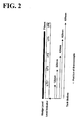
- a sludge level indicator designed to monitor the melting process of the sludge by measuring current level of the sludge, is mounted in the crude oil storage tank, as shown in Fig. 2.
- Said sludge level indicator contains a plural number of thermocouple tips located at regular intervals.
- the temperature of thermocouple tips located in the tank is mainly affected by heat of fusion of the sludge owing to low thermal conductivity of the sludge.
- the position of the sludge at equivalent temperature indicates the current sludge level. This means that the sludge is totally melted when the temperature of the bottom tip in the sludge level indicator is equal to the top tip. Accordingly, a completion point of time of the sludge removal process can be found.
- the temperature may be lowered by the consumption of heat of fusion and external dissipation of heat during the sludge removal, so the mixture of the sludge and thermal oil is circulated through heat exchanger-mounted circulation lines and thus may be maintained at constant temperature range.
- inorganics e.g., inorganic components such as mud, rust dregs and so on
- inorganic components such as mud, rust dregs and so on
- the temperature of 60 °C or higher is required is that the higher the temperature, the lower the viscosity, thus improving removal of inorganics.
- Compounds such as dispersion agents, may be optionally used, as necessary.
- Said procedure may be performed in the crude oil storage tank itself, or in an additional separation tank connected to the tank.
- stirring is stopped and then the mixture of said thermal oil and sludge is transferred from the crude oil storage tank to the separation tank through out of service line.
- a stripping tank is used as the separation tank, additional cost is not required.
- the crude oil storage tank may be opened for regular repair by common washing procedures or may be refilled with crude oil.
- the inorganics accumulated in the separation tank need not be removed so long as they do not affect fusible volume of the tank. But, when being removed, the accumulated inorganics are manually removed by scraping after opening the separation tank.
- recovered oil may be used as marine oil or a feed for secondary treatment processes.
- the recovered oil contains slightly more wax than thermal oil but can be used for said application.
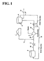
- Fig. 1 shows an embodiment of the sludge removal and the oil withdrawal process of the present invention.
- the sludge removal and the oil withdrawal lines comprise a thermal oil storage tank 1, a crude oil storage tank 2, a separation tank 3, a pump 4 and a heat exchanger 5.
- the thermal oil yielded from an oil refining step is stored in the thermal oil storage tank 1 at 80-130 °C according to a post-treatment step, and may be stored at temperatures below said temperature range.
- the temperature of the thermal oil is a process operation temperature (i.e., 50-130 °C)
- said thermal oil is transferred to the crude oil storage tank 2 under operation of the pump 4 and the heat exchanger 5.
- the heat exchanger 5 is responsible for supplying the heat obtained by steam introduced when the temperature of the thermal oil is 50 °C or lower, to the thermal oil. Simultaneously, the exchanger compensates for a lowering of the temperature of the mixture comprising thermal oil and sludge caused by the consumption of heat of fusion and heat loss during the sludge removal.
- the thermal oil is circulated to the separation tank 3 until it reaches 50-130 °C, the temperature required for the sludge removal process by the mounted pump 4 and heat exchanger 5.
- the valve 7 is closed, and the thermal oil is circulated to the separation tank 3 through inner loop lines 14 and 15.
- the thermal oil is transferred to the crude oil storage tank 2 with opening the valve 7 under the operation of the pump 4 and the thermal exchanger 5.
- the temperature and the amount of the thermal oil for effective sludge removal are preferably determined according to the heat loss through pipelines.
- the crude oil in the tank 2 is discharged as fully as possible through an external line 18. At that time, it is preferred that the amount of remaining crude oil is minimized for safety reasons. Then, the accumulated amount is measured through the sludge level and, as shown in Fig. 2, the sludge level indicator 6 including a plural number of thermocouple tips is mounted to a desired location in the tank 2.
- the melting begins from the upper parts of the sludge.
- the mixture comprising the thermal oil and the sludge is circulated through external loop lines 17 and 14 while maintaining constant temperature using said pump 4 and heat exchanger 5 by on-off control of the valve.
- inorganics are settled and thus separated from the oil.
- a period of time necessary for settling is preferably about 8 hours.
- Inorganics-removed oil is back-transferred to the tank 1 via the lines 11 and 16 and then stored.
- recovered oil may be used as marine oil or a feed for the secondary treatment process.
- the atmospheric residue was heated by use of a heat exchanger made of copper tubes, and water was circulated on the exterior using a thermostat as a heat source.
- a stirrer was provided at a central position and operated at a low speed of 20 rpm. As such, operation temperature was 65-80 °C.
- a thermocouple having multi-tips was installed in the beaker to observe the change of the sludge level.
- the sludge and the atmospheric residue (B-C, which refers to an atmospheric residue in high sulfur content of crude oil storage tank) were mixed at a volume ratio of 1:4 in a 3 L glass decanter, and melted with stirring at 80 °C. Samples in an oven maintained at 80 °C were extracted according to time, and measured for content of inorganics and ignition loss by ICP (inductively coupled plasma).
- Vanadium contained in the sludge did not affect separation by settling because of being present in a state combined with hydrocarbons. Inorganics separable by settling were rust components resulting from corrosion of the storage tank and components contained in salt water. The sludge contained iron at thousands to tens of thousands ppm.
- the test was conducted as a One-Through test by use of only the atmospheric residue of 80 °C as a heat source, without the heat exchanger and the pump, to preferentially determine investment needs and technique effectiveness.
- the used crude oil storage tank was a 750,000 bbl tank for storing crude oil with high sulfur content. Before the test, the sludge was accumulated in the amount of about 2,540 tons (approximately 16,000 bbl, assuming specific gravity of 1) in the tank.
- the main object of said test was to verify the effectiveness of the sludge removal process, rather than to use recovered oil, so the sludge level was observed using 84,000 bbl of atmospheric residue of 80 °C as the heat source. As such, the volume ratio of the atmospheric residue to sludge was 5.3:1. Said atmospheric residue was introduced to the crude oil storage tank through conventional pipelines.
- the crude oil was discharged before the introduction of the thermal oil, and the amount of the sludge was measured, followed by mounting the sludge level indicator, as shown in Fig. 2.
- LIT shows the position of thermocouple tips in the sludge level indicator. Each tip shows the temperature of the bulk phase after the sludge was melted. That is, the position indicates the level of the sludge. From the result of the test, it can be seen that said sludge level indicator is suitable to monitor progress of the sludge removal process.
- Figs. 5 and 6 The result of the test is illustrated in Figs. 5 and 6.
- Fig. 5 there is shown the temperature changes of each thermocouple tip.
- the cause of the temperature of the bulk phase being reduced is construed to be the sludge fusion heat and the heat loss through the tank wall.
- the temperature reduction is balanced by the heat supplied from the heat exchanger, separately mounted, and the temperature of the bulk phase is constantly maintained.
- external temperature was approximately 20 °C. From the results shown in Fig. 5, it can be seen that, even though the atmospheric residue at 80 °C is used as the heat source in the amount of about 84,000 bbl, the sludge removal efficiency is 80 %, so that the process of the present invention can be applied to actual work sites.
- Fig. 6 shows the temperature change of bulk phase and sludge level of a mixture comprising atmospheric residue and sludge in the crude oil storage tank. 8 hours are required to provide the atmospheric residue, and 17 hours to melt the sludge.
- the method for removing sludge and recovering oil therefrom of the present invention has advantages that air pollution can be minimized because of using the closed system, the operation is easily performed with minimal initial investment cost, the cleaning time of the tank is drastically reduced, and the sludge can be continuously removed.
- the thermal oil of high temperature yielded from the oil refining process may be used to remove the sludge, thereby creating economic benefit.
- the recovered oil can be used as fuel oil, marine oil, or a feed for secondary treatment process, such as upgrading processes of heavy oil.
Landscapes
- Chemical & Material Sciences (AREA)
- Engineering & Computer Science (AREA)
- Oil, Petroleum & Natural Gas (AREA)
- Chemical Kinetics & Catalysis (AREA)
- General Chemical & Material Sciences (AREA)
- Organic Chemistry (AREA)
- Wood Science & Technology (AREA)
- Life Sciences & Earth Sciences (AREA)
- Mechanical Engineering (AREA)
- Physics & Mathematics (AREA)
- Thermal Sciences (AREA)
- Production Of Liquid Hydrocarbon Mixture For Refining Petroleum (AREA)
- Treatment Of Sludge (AREA)
- Cleaning In General (AREA)
Abstract
Description
| Properties | Atmospheric Residue | Vacuum Residue | Vacuum Gas Oil |
| Boiling point (°C) | 260-550 | 270-580 | 250-270 |
| Specific gravity | 0.90-0.99 | 0.98-0.99 | 0.9-0.95 |
| DISTILLATION DATA OF ATMOSPHERIC RESIDUE | |
| Vol% | Temp. (°C) |
| IBP | 208 |
| 5 | 302 |
| 10 | 343 |
| 20 | 399 |
| 30 | 435 |
| 40 | 466 |
| 50 | 500 |
| 57 | 522 |
| Specific gravity: 0.9526 | |
| Viscosity: 24 cP at 50 °C |
| DISTILLATION DATA OF SLUDGE | |
| Vol% | Temp. (°C) |
| IBP | 245 |
| 5 | 314 |
| 10 | 344 |
| 20 | 356 |
| 30 | 357 |
| 40 | 362 |
| 50 | 365 |
| 60 | 371 |
| 70 | 386 |
| 80 | 498 |
| 87 | 565 |
| Specific gravity: 0.9972 | |
| American Petroleum Institute Degree: 10.4 |
Claims (10)
- A method for removing sludge and recovering oil therefrom, comprising the steps of:(a) introducing thermal oil yielded from an oil refining process, to sludge accumulated in a crude oil storage tank, at a volume ratio of 3:1 to 20:1, said thermal oil being selected from the group consisting of atmospheric residue, vacuum residue and vacuum gas oil;(b) melting the sludge until a mixture of said thermal oil and the sludge has a homogeneous temperature distribution with or without stirring said introduced thermal oil and sludge;(c) settling inorganics by allowing the mixture of said thermal oil and sludge to stand in said storage tank or an additional separation tank connected to said storage tank; and(d) recovering oil from the mixture of said thermal oil and sludge.
- The method as defined in claim 1, wherein said (b) step is carried out at 50 to 130 °C.
- The method as defined in claim 1, wherein said (c) step is carried out at 60 to 130 °C.
- The method as defined in claim 1, wherein the temperature of the thermal oil introduced into the crude oil storage tank in said (a) step is 80 to 130 °C.
- The method as defined in claim 1, wherein the boiling point of said thermal oil is 250 to 580 °C.
- The method as defined in claim 1, wherein the specific gravity of said thermal oil is 0.9 to 1.0.
- The method as defined in claim 1, wherein a sludge level indicator including a plural number of thermocouple tips located at regular intervals is mounted in said crude oil storage tank, and a point of time at which the bottom tip of said sludge level indicator becomes equal in temperature to the top tip is determined as a completion point of time of said (b) step.
- The method as defined in claim 1, further comprising the step of providing said recovered oil as fuel oil, marine oil or a feed for secondary treatment processes.
- The method as defined in claim 1, wherein said separation tank is a stripping tank.
- A method for removing sludge in crude oil storage tank and recovering oil therefrom, comprising the steps of:(a) introducing thermal oil from a thermal oil storage tank into a sludge-accumulated crude oil storage tank at a volume ratio of thermal oil to sludge of 3:1 to 20:1 under operation of a pump and a heat exchanger, said thermal oil being selected from the group consisting of atmospheric residue, vacuum residue, and vacuum gas oil, wherein if the thermal oil stored in said thermal oil storage tank is 50 °C or higher, thermal oil is directly introduced into said crude oil storage tank under operation of said pump and heat exchanger, while if thermal oil is less than 50 °C, the thermal oil is circulated to a separation tank under said pump and heat exchanger until reaching 50 to 130 °C, and then introduced into said crude oil storage tank;(b) melting the sludge at 50 to 130 °C by use of said introduced thermal oil with or without stirring, wherein a mixture of said thermal oil and sludge is introduced into said crude oil storage tank, and then melted until the temperature of the bottom tip in the sludge level indicator including a plural number of thermocouple tips accords with that of the top tip, said mixture of the thermal oil and sludge being circulated for maintaining said temperature range under operation of said heat exchanger;(c) introducing said molten mixture of thermal oil and sludge into a separation tank connected to said crude oil storage tank;(d) settling inorganics by allowing said mixture of thermal oil and sludge to stand at 60 to 130 °C in said separation tank; and(e) recovering oil from said mixture of thermal oil and sludge.
Applications Claiming Priority (2)
| Application Number | Priority Date | Filing Date | Title |
|---|---|---|---|
| KR10-2001-0008398A KR100475172B1 (en) | 2001-02-20 | 2001-02-20 | Method for Removing Sludges in A Crude Oil Tank and Recovering Oil Therefrom |
| KR2001008398 | 2001-02-20 |
Publications (3)
| Publication Number | Publication Date |
|---|---|
| EP1232804A2 true EP1232804A2 (en) | 2002-08-21 |
| EP1232804A3 EP1232804A3 (en) | 2003-01-15 |
| EP1232804B1 EP1232804B1 (en) | 2008-09-24 |
Family
ID=19705993
Family Applications (1)
| Application Number | Title | Priority Date | Filing Date |
|---|---|---|---|
| EP20020003720 Expired - Lifetime EP1232804B1 (en) | 2001-02-20 | 2002-02-19 | Method for removing sludge in crude oil tank and recovering oil therefrom |
Country Status (7)
| Country | Link |
|---|---|
| US (1) | US6673231B2 (en) |
| EP (1) | EP1232804B1 (en) |
| JP (1) | JP4227752B2 (en) |
| KR (1) | KR100475172B1 (en) |
| CN (1) | CN1230258C (en) |
| DE (1) | DE60229016D1 (en) |
| MY (1) | MY136348A (en) |
Cited By (5)
| Publication number | Priority date | Publication date | Assignee | Title |
|---|---|---|---|---|
| CN102125919A (en) * | 2011-01-14 | 2011-07-20 | 华油惠博普科技股份有限公司 | Mechanical cleaning device for product oil tank |
| CN102319709A (en) * | 2011-05-24 | 2012-01-18 | 合肥通用机械研究院 | Method for crushing and cleaning oil sludge in oil storage tank by using liquid cannon |
| CN105541063A (en) * | 2016-01-05 | 2016-05-04 | 杭州造品科技有限公司 | Integrated oil sludge treatment systems and use method thereof |
| CN105728410A (en) * | 2016-05-09 | 2016-07-06 | 上海理工大学 | Vehicle-mounted movable oil stain circulating cleaning device |
| CN110104704A (en) * | 2019-05-31 | 2019-08-09 | 青岛贝索科技有限公司 | A kind of method and device of sour water processing sump oil |
Families Citing this family (35)
| Publication number | Priority date | Publication date | Assignee | Title |
|---|---|---|---|---|
| US7087189B2 (en) * | 2002-03-18 | 2006-08-08 | National Starch Chemical Investment Holding Co | Multifunctional calcium carbonate and calcium phosphate scale inhibitor |
| JP4518409B2 (en) * | 2003-03-31 | 2010-08-04 | Hoya株式会社 | Cleaning method |
| US7559372B2 (en) | 2004-04-13 | 2009-07-14 | Coriba Technologies, L.L.C. | Composition and process for enhanced oil recovery |
| CN101124302A (en) * | 2004-09-27 | 2008-02-13 | 科里巴技术有限公司 | Compositions and methods for extracting bitumen from oil sands |
| US7976640B2 (en) * | 2005-04-04 | 2011-07-12 | Exxonmobil Research & Engineering Company | On-line heat exchanger cleaning method |
| US7678201B2 (en) * | 2005-07-22 | 2010-03-16 | Coriba Technologies, L.L.C. | Composition and process for the removal and recovery of hydrocarbons from substrates |
| DE102006020427B4 (en) * | 2006-04-25 | 2008-05-29 | Thomas Falkenstein Gewerbliche Vermietung Und Verpachtung E.K. | Method and device for cleaning the interior of a tank |
| US20070283981A1 (en) * | 2006-06-08 | 2007-12-13 | Stewart Tracy E | Method for cleaning storage tanks |
| US20080047871A1 (en) * | 2006-08-23 | 2008-02-28 | Exxonmobil Research And Engineering Company | Crude oil storage and tank maintenance |
| JP5244467B2 (en) * | 2008-06-06 | 2013-07-24 | 忠幸 ▲吉▼田 | Bill pit scum treatment method and fuel recovery method |
| US20110094937A1 (en) * | 2009-10-27 | 2011-04-28 | Kellogg Brown & Root Llc | Residuum Oil Supercritical Extraction Process |
| US10168105B2 (en) | 2010-05-04 | 2019-01-01 | Basf Se | Device and method for storing heat |
| ES2453094T3 (en) * | 2010-05-04 | 2014-04-04 | Basf Se | Device and procedure for heat accumulation |
| US8728300B2 (en) | 2010-10-15 | 2014-05-20 | Kellogg Brown & Root Llc | Flash processing a solvent deasphalting feed |
| JP6004562B2 (en) * | 2011-04-14 | 2016-10-12 | システム機工株式会社 | Oil recovery equipment for crude oil sludge |
| JP5925189B2 (en) * | 2011-04-14 | 2016-05-25 | システム機工株式会社 | Oil recovery method in crude oil sludge |
| CN102350431B (en) * | 2011-07-28 | 2013-07-17 | 中国石油大学(北京) | Method for separating oil content of organic matters from crude oil-containing wastes |
| CN102500141B (en) * | 2011-10-28 | 2014-01-22 | 克拉玛依市金牛工程建设有限责任公司 | Sewage precipitation tank online washing machine, device for online washing of sewage precipitation tank and recycling of crude oil and using method |
| CN103143540A (en) * | 2011-12-07 | 2013-06-12 | 中船重工(沈阳)辽海输油设备有限公司 | Integrated system in linked network |
| CN103143534A (en) * | 2011-12-07 | 2013-06-12 | 中船重工(沈阳)辽海输油设备有限公司 | Integrated single power lever |
| BR102012015763A2 (en) * | 2012-06-26 | 2014-12-02 | Joel Ligiero Junior Vargas | METHOD FOR CLEANING A STORAGE TANK USING SKIMMER AND USING SKIMMER. |
| KR102294434B1 (en) * | 2014-06-09 | 2021-08-26 | 에스케이이노베이션 주식회사 | Recycling method of sludge recovery oil |
| KR20160026211A (en) | 2014-08-29 | 2016-03-09 | 삼성중공업 주식회사 | Apparatus for cleaning of oil tank |
| JP2016077992A (en) | 2014-10-20 | 2016-05-16 | ソフタード工業株式会社 | Method and apparatus for cleaning oil tank |
| KR101519637B1 (en) * | 2014-12-05 | 2015-05-12 | 주식회사 삼미정공 | Hemming device using rollers |
| CA2970295A1 (en) * | 2014-12-08 | 2016-06-16 | William E. Ardrey | System and method for measuring and processing petroleum |
| CA2989100C (en) * | 2015-06-12 | 2022-11-29 | Cosmo Oil Co., Ltd. | Method for recovering oil by heating, stirring and centrifugation of a crude oil sludge |
| CN105149306B (en) * | 2015-08-18 | 2017-08-08 | 韦亦姣 | The cleaning method and its equipment of a kind of datonation-inhibition oil tank |
| KR20200126060A (en) | 2019-04-29 | 2020-11-06 | 손성근 | crude oil tank cleaning system |
| US11203048B2 (en) * | 2019-06-05 | 2021-12-21 | Andrew Foley | Vacuum vessels for melting vegetable oil gums and associated methods of use |
| CN110328200B (en) * | 2019-07-02 | 2024-04-23 | 河南开祥精细化工有限公司 | Pipeline deoiling system and method thereof |
| CN114433580B (en) * | 2020-10-20 | 2023-05-26 | 中国石油化工股份有限公司 | Online oil sludge flushing device and flushing method for storage tank bottom plate |
| KR102551028B1 (en) | 2021-08-09 | 2023-07-03 | 손성근 | crude oil tank cleaning system |
| CN114260290B (en) * | 2021-12-09 | 2023-10-13 | 安徽科技学院 | Rectification residue handles with broken bucket of high efficiency and purifies integral type processing apparatus |
| CN118665872A (en) * | 2024-05-30 | 2024-09-20 | 重庆科技大学 | Thickened oil tank convenient for thickened oil recovery and oil tank cleaning and recovery and cleaning method |
Family Cites Families (15)
| Publication number | Priority date | Publication date | Assignee | Title |
|---|---|---|---|---|
| US2462A (en) * | 1842-02-21 | Worked buttons on the heads | ||
| US2066166A (en) * | 1935-07-25 | 1936-12-29 | Laval Separator Co De | Process of treating a cold mixture of acid sludge, oil, and wax |
| US4426233A (en) * | 1981-09-11 | 1984-01-17 | Taiho Industries Co. Ltd. | Method for disposal of sludge in floating roof type oil tank |
| KR900004094B1 (en) * | 1988-04-18 | 1990-06-15 | 김만조 | How to recover oil from oil sludge |
| GB2227648B (en) * | 1989-02-01 | 1993-07-28 | Great Eastern Petroleum | Method and apparatus for the removal of black oil residues from tanks |
| ATE130676T1 (en) * | 1989-08-22 | 1995-12-15 | Siemens Ag | MEASURING DEVICE AND METHOD FOR DETERMINING THE FILL LEVEL IN LIQUID CONTAINERS, PREFERABLY FOR TANK SYSTEMS. |
| US5085710A (en) * | 1989-10-31 | 1992-02-04 | Nalco Chemical Company | Method of using an aqueous chemical system to recover hydrocarbon and minimize wastes from sludge deposits in oil storage tanks |
| US5056363A (en) * | 1990-03-08 | 1991-10-15 | Industrial Engineering And Equipment Company, Inc. | Integral temperature and liquid level sensor and control |
| DE4224953C1 (en) * | 1992-07-29 | 1993-12-16 | Mineraloel Raffinerie Dollberg | Process for the treatment of industrial sludges containing oil |
| BR9304238A (en) * | 1993-10-15 | 1995-06-06 | Petroleo Brasileiro Sa | Thermo-chemical cleaning of storage tanks |
| US6069002A (en) * | 1994-04-11 | 2000-05-30 | Aplc, Inc. | System and process for in tank treatment of crude oil sludges to recover hydrocarbons and aid in materials separation |
| US5653865A (en) * | 1995-11-06 | 1997-08-05 | Miyasaki; Mace T. | Method and apparatus for recovering the fuel value of crude oil sludge |
| DE19702462C1 (en) * | 1997-01-24 | 1998-04-16 | Dietrich Sobinger | Cleaning method for oil tanks etc. |
| LU90183B1 (en) * | 1997-12-15 | 1998-04-06 | Petrojet Limited | Process for cleaning an oil tank and device for carrying out said process |
| US6371137B1 (en) * | 1998-12-03 | 2002-04-16 | Robert A. Heath | Tank cleaning apparatus |
-
2001
- 2001-02-20 KR KR10-2001-0008398A patent/KR100475172B1/en not_active Expired - Fee Related
- 2001-09-24 US US09/962,359 patent/US6673231B2/en not_active Expired - Fee Related
-
2002
- 2002-02-07 MY MYPI20020429A patent/MY136348A/en unknown
- 2002-02-19 EP EP20020003720 patent/EP1232804B1/en not_active Expired - Lifetime
- 2002-02-19 DE DE60229016T patent/DE60229016D1/en not_active Expired - Fee Related
- 2002-02-20 JP JP2002042689A patent/JP4227752B2/en not_active Expired - Fee Related
- 2002-02-20 CN CNB021051534A patent/CN1230258C/en not_active Expired - Fee Related
Cited By (7)
| Publication number | Priority date | Publication date | Assignee | Title |
|---|---|---|---|---|
| CN102125919A (en) * | 2011-01-14 | 2011-07-20 | 华油惠博普科技股份有限公司 | Mechanical cleaning device for product oil tank |
| CN102125919B (en) * | 2011-01-14 | 2012-08-15 | 华油惠博普科技股份有限公司 | Mechanical cleaning device for product oil tank |
| CN102319709A (en) * | 2011-05-24 | 2012-01-18 | 合肥通用机械研究院 | Method for crushing and cleaning oil sludge in oil storage tank by using liquid cannon |
| CN105541063A (en) * | 2016-01-05 | 2016-05-04 | 杭州造品科技有限公司 | Integrated oil sludge treatment systems and use method thereof |
| CN105728410A (en) * | 2016-05-09 | 2016-07-06 | 上海理工大学 | Vehicle-mounted movable oil stain circulating cleaning device |
| CN110104704A (en) * | 2019-05-31 | 2019-08-09 | 青岛贝索科技有限公司 | A kind of method and device of sour water processing sump oil |
| CN110104704B (en) * | 2019-05-31 | 2023-07-25 | 青岛贝索科技有限公司 | Method and device for treating dirty oil by sulfur-containing sewage |
Also Published As
| Publication number | Publication date |
|---|---|
| EP1232804A3 (en) | 2003-01-15 |
| DE60229016D1 (en) | 2008-11-06 |
| MY136348A (en) | 2008-09-30 |
| EP1232804B1 (en) | 2008-09-24 |
| CN1371765A (en) | 2002-10-02 |
| CN1230258C (en) | 2005-12-07 |
| JP4227752B2 (en) | 2009-02-18 |
| US6673231B2 (en) | 2004-01-06 |
| KR100475172B1 (en) | 2005-03-08 |
| US20020153279A1 (en) | 2002-10-24 |
| JP2002338969A (en) | 2002-11-27 |
| KR20020068133A (en) | 2002-08-27 |
Similar Documents
| Publication | Publication Date | Title |
|---|---|---|
| US6673231B2 (en) | Method for removing sludge in crude oil tank and recovering oil therefrom | |
| US4364776A (en) | Recovery of heavy hydrocarbons from oil sludge | |
| CA2306133C (en) | Process for upgrading heavy crude oil production | |
| EP2964731B1 (en) | Process to upgrade and desulfurize crude oil by supercritical water | |
| US5540784A (en) | Pressurized closed flow cleaning system | |
| US10077405B2 (en) | Petroleum crude oil desalting process and unit | |
| RU2106211C1 (en) | Method for thermochemical cleaning of reservoirs for storing petroleum products | |
| US5085242A (en) | Method and apparatus for the removal of black oil residues from tanks | |
| US7244364B1 (en) | FCC-CFD cat' fine desalting: a method and system for separating hydrocarbons and extracting catalyst fines from a slurry oil/catalyst fines/diluent mixture | |
| CA2021185C (en) | Process for separation of hydrocarbon from tar sands froth | |
| US4897205A (en) | Method for treating waste material | |
| US4206001A (en) | Cleaning method for refining process rundown tank | |
| JP2010501333A (en) | Crude oil storage and tank maintenance | |
| JP5925189B2 (en) | Oil recovery method in crude oil sludge | |
| US20170190987A1 (en) | Optimization of a Method for Isolation of Paraffinic Hydrocarbons | |
| USRE35815E (en) | Method for treating waste material | |
| KR102294434B1 (en) | Recycling method of sludge recovery oil | |
| CA1183791A (en) | Recovery of heavy hydrocarbons from oil sludge | |
| RU2732242C1 (en) | Method for producing black oil from steaming and washing mixtures of oil products | |
| Kremer et al. | On-Line Method for Reducing Sludge Volume in Crude Oil Storage Tanks | |
| Kolaczkowski | School of Chemical Engineering University of Bath | |
| IT202000015379A1 (en) | Device for the separation through graphene of the hydrocarbons present in a fluid | |
| RO105900B1 (en) | Cleaning process and plant of high capacity oil tanks |
Legal Events
| Date | Code | Title | Description |
|---|---|---|---|
| PUAI | Public reference made under article 153(3) epc to a published international application that has entered the european phase |
Free format text: ORIGINAL CODE: 0009012 |
|
| AK | Designated contracting states |
Kind code of ref document: A2 Designated state(s): AT BE CH CY DE DK ES FI FR GB GR IE IT LI LU MC NL PT SE TR |
|
| AX | Request for extension of the european patent |
Free format text: AL;LT;LV;MK;RO;SI |
|
| PUAL | Search report despatched |
Free format text: ORIGINAL CODE: 0009013 |
|
| AK | Designated contracting states |
Kind code of ref document: A3 Designated state(s): AT BE CH CY DE DK ES FI FR GB GR IE IT LI LU MC NL PT SE TR |
|
| AX | Request for extension of the european patent |
Free format text: AL;LT;LV;MK;RO;SI |
|
| 17P | Request for examination filed |
Effective date: 20030711 |
|
| AKX | Designation fees paid |
Designated state(s): DE FR GB |
|
| 17Q | First examination report despatched |
Effective date: 20060223 |
|
| RAP1 | Party data changed (applicant data changed or rights of an application transferred) |
Owner name: SK ENERGY CO., LTD. |
|
| GRAP | Despatch of communication of intention to grant a patent |
Free format text: ORIGINAL CODE: EPIDOSNIGR1 |
|
| GRAC | Information related to communication of intention to grant a patent modified |
Free format text: ORIGINAL CODE: EPIDOSCIGR1 |
|
| GRAS | Grant fee paid |
Free format text: ORIGINAL CODE: EPIDOSNIGR3 |
|
| GRAA | (expected) grant |
Free format text: ORIGINAL CODE: 0009210 |
|
| RIN1 | Information on inventor provided before grant (corrected) |
Inventor name: PARK, SUNG-KIL Inventor name: KWAK, JONG-WON Inventor name: CHOI, JUNE-TAE Inventor name: CHOI, CHANG-HYO Inventor name: YOON, DAE-SEOG Inventor name: KIM, MYUNG-JUN |
|
| AK | Designated contracting states |
Kind code of ref document: B1 Designated state(s): DE FR GB |
|
| REG | Reference to a national code |
Ref country code: GB Ref legal event code: FG4D |
|
| REF | Corresponds to: |
Ref document number: 60229016 Country of ref document: DE Date of ref document: 20081106 Kind code of ref document: P |
|
| PGFP | Annual fee paid to national office [announced via postgrant information from national office to epo] |
Ref country code: DE Payment date: 20090219 Year of fee payment: 8 |
|
| PGFP | Annual fee paid to national office [announced via postgrant information from national office to epo] |
Ref country code: GB Payment date: 20090219 Year of fee payment: 8 |
|
| PLBE | No opposition filed within time limit |
Free format text: ORIGINAL CODE: 0009261 |
|
| STAA | Information on the status of an ep patent application or granted ep patent |
Free format text: STATUS: NO OPPOSITION FILED WITHIN TIME LIMIT |
|
| 26N | No opposition filed |
Effective date: 20090625 |
|
| PGFP | Annual fee paid to national office [announced via postgrant information from national office to epo] |
Ref country code: FR Payment date: 20090213 Year of fee payment: 8 |
|
| GBPC | Gb: european patent ceased through non-payment of renewal fee |
Effective date: 20100219 |
|
| REG | Reference to a national code |
Ref country code: FR Ref legal event code: ST Effective date: 20101029 |
|
| PG25 | Lapsed in a contracting state [announced via postgrant information from national office to epo] |
Ref country code: FR Free format text: LAPSE BECAUSE OF NON-PAYMENT OF DUE FEES Effective date: 20100301 |
|
| PG25 | Lapsed in a contracting state [announced via postgrant information from national office to epo] |
Ref country code: DE Free format text: LAPSE BECAUSE OF NON-PAYMENT OF DUE FEES Effective date: 20100901 |
|
| PG25 | Lapsed in a contracting state [announced via postgrant information from national office to epo] |
Ref country code: GB Free format text: LAPSE BECAUSE OF NON-PAYMENT OF DUE FEES Effective date: 20100219 |