EP1232494B1 - Gain-smoothing in wideband speech and audio signal decoder - Google Patents
Gain-smoothing in wideband speech and audio signal decoder Download PDFInfo
- Publication number
- EP1232494B1 EP1232494B1 EP00978928A EP00978928A EP1232494B1 EP 1232494 B1 EP1232494 B1 EP 1232494B1 EP 00978928 A EP00978928 A EP 00978928A EP 00978928 A EP00978928 A EP 00978928A EP 1232494 B1 EP1232494 B1 EP 1232494B1
- Authority
- EP
- European Patent Office
- Prior art keywords
- gain
- codevector
- signal
- wideband signal
- smoothed
- Prior art date
- Legal status (The legal status is an assumption and is not a legal conclusion. Google has not performed a legal analysis and makes no representation as to the accuracy of the status listed.)
- Expired - Lifetime
Links
- 238000009499 grossing Methods 0.000 title claims abstract description 36
- 230000005236 sound signal Effects 0.000 title description 10
- 238000000034 method Methods 0.000 claims abstract description 74
- 230000004044 response Effects 0.000 claims abstract description 31
- 239000013598 vector Substances 0.000 claims description 57
- 230000003595 spectral effect Effects 0.000 claims description 35
- 238000004891 communication Methods 0.000 claims description 33
- 230000002457 bidirectional effect Effects 0.000 claims description 25
- 230000010267 cellular communication Effects 0.000 claims description 21
- 230000003044 adaptive effect Effects 0.000 claims description 15
- 230000001413 cellular effect Effects 0.000 claims description 9
- 238000013507 mapping Methods 0.000 claims description 6
- 238000004519 manufacturing process Methods 0.000 claims description 4
- 230000005284 excitation Effects 0.000 description 46
- 238000003786 synthesis reaction Methods 0.000 description 35
- 230000015572 biosynthetic process Effects 0.000 description 33
- 238000005070 sampling Methods 0.000 description 15
- 238000013459 approach Methods 0.000 description 14
- 230000006870 function Effects 0.000 description 13
- 238000012546 transfer Methods 0.000 description 12
- 238000013139 quantization Methods 0.000 description 11
- 238000001914 filtration Methods 0.000 description 10
- 238000001228 spectrum Methods 0.000 description 10
- 238000007493 shaping process Methods 0.000 description 7
- 238000010586 diagram Methods 0.000 description 6
- 230000008569 process Effects 0.000 description 4
- 230000011664 signaling Effects 0.000 description 4
- 230000007774 longterm Effects 0.000 description 3
- 238000007781 pre-processing Methods 0.000 description 3
- 230000009467 reduction Effects 0.000 description 3
- 230000005540 biological transmission Effects 0.000 description 2
- 238000005259 measurement Methods 0.000 description 2
- 238000012805 post-processing Methods 0.000 description 2
- 101000822695 Clostridium perfringens (strain 13 / Type A) Small, acid-soluble spore protein C1 Proteins 0.000 description 1
- 101000655262 Clostridium perfringens (strain 13 / Type A) Small, acid-soluble spore protein C2 Proteins 0.000 description 1
- 101000655256 Paraclostridium bifermentans Small, acid-soluble spore protein alpha Proteins 0.000 description 1
- 101000655264 Paraclostridium bifermentans Small, acid-soluble spore protein beta Proteins 0.000 description 1
- 238000010420 art technique Methods 0.000 description 1
- 230000001143 conditioned effect Effects 0.000 description 1
- 230000003247 decreasing effect Effects 0.000 description 1
- 230000001419 dependent effect Effects 0.000 description 1
- 230000000694 effects Effects 0.000 description 1
- 239000003623 enhancer Substances 0.000 description 1
- 230000002708 enhancing effect Effects 0.000 description 1
- 239000000284 extract Substances 0.000 description 1
- 230000000873 masking effect Effects 0.000 description 1
- 239000011159 matrix material Substances 0.000 description 1
- 238000010295 mobile communication Methods 0.000 description 1
- 230000008447 perception Effects 0.000 description 1
- 230000000737 periodic effect Effects 0.000 description 1
- 238000012545 processing Methods 0.000 description 1
- 230000008929 regeneration Effects 0.000 description 1
- 238000011069 regeneration method Methods 0.000 description 1
- 230000000717 retained effect Effects 0.000 description 1
- 238000011524 similarity measure Methods 0.000 description 1
- 230000002194 synthesizing effect Effects 0.000 description 1
- 238000012360 testing method Methods 0.000 description 1
Images


Classifications
-
- G—PHYSICS
- G10—MUSICAL INSTRUMENTS; ACOUSTICS
- G10L—SPEECH ANALYSIS TECHNIQUES OR SPEECH SYNTHESIS; SPEECH RECOGNITION; SPEECH OR VOICE PROCESSING TECHNIQUES; SPEECH OR AUDIO CODING OR DECODING
- G10L19/00—Speech or audio signals analysis-synthesis techniques for redundancy reduction, e.g. in vocoders; Coding or decoding of speech or audio signals, using source filter models or psychoacoustic analysis
- G10L19/04—Speech or audio signals analysis-synthesis techniques for redundancy reduction, e.g. in vocoders; Coding or decoding of speech or audio signals, using source filter models or psychoacoustic analysis using predictive techniques
- G10L19/08—Determination or coding of the excitation function; Determination or coding of the long-term prediction parameters
- G10L19/083—Determination or coding of the excitation function; Determination or coding of the long-term prediction parameters the excitation function being an excitation gain
-
- G—PHYSICS
- G10—MUSICAL INSTRUMENTS; ACOUSTICS
- G10L—SPEECH ANALYSIS TECHNIQUES OR SPEECH SYNTHESIS; SPEECH RECOGNITION; SPEECH OR VOICE PROCESSING TECHNIQUES; SPEECH OR AUDIO CODING OR DECODING
- G10L19/00—Speech or audio signals analysis-synthesis techniques for redundancy reduction, e.g. in vocoders; Coding or decoding of speech or audio signals, using source filter models or psychoacoustic analysis
- G10L2019/0001—Codebooks
- G10L2019/0012—Smoothing of parameters of the decoder interpolation
Definitions
- the present invention relates to a gain-smoothing method and device implemented in a wideband signal encoder.
- a speech encoder converts a speech signal into a digital bitstream which is transmitted over a communication channel (or stored in a storage medium).
- the speech signal is digitized (sampled and quantized usually with 16-bits per sample) and the speech encoder has the role of representing these digital samples with a smaller number of bits while maintaining a good subjective speech quality.
- the speech decoder or synthesizer processes the transmitted or stored bit stream to convert it back to a sound signal, for example a speech/audio signal.
- CELP Code Excited Linear Prediction
- An excitation signal is determined in each subframe, which usually consists of two components: one from the past excitation (also called pitch contribution or adaptive codebook) and the other from an innovative codebook (also called fixed codebook).
- This excitation signal is transmitted and used at the decoder as the input of the LP synthesis filter in order to obtain a synthesized speech.
- An innovative codebook in the CELP context is an indexed set of N-sample-long sequences which will be referred to as N-dimensional codevectors.
- each block of N samples is synthesized by filtering an appropriate codevector from an innovative codebook through time varying filters modeling the spectral characteristics of the speech signal.
- the synthesis output is computed for all, or a subset, of the codevectors from the innovative codebook (codebook search).
- the retained codevector is the one producing the synthesis output closest to the original speech signal according to a perceptually weighted distortion measure. This perceptual weighting is performed using a so-called perceptual weighting filter, which is usually derived from the LP synthesis filter.
- the CELP model has been very successful in encoding telephone band sound signals, and several CELP-based standards exist in a wide range of applications, especially in digital cellular applications.
- the sound signal In the telephone band, the sound signal is band-limited to 200-3400 Hz and sampled at 8000 samples/sec.
- the sound signal In wideband speech/audio applications, the sound signal is band-limited to 50-7000 Hz and sampled at 16000 samples/sec.
- Document US-A-5 195 168 describes a device for substantially reconstructing a signal.
- the signal is partitioned into successive time intervals. Each time interval has an input reference signal with a set of vectors and at least one representative electrical signal for each input reference signal.
- the device uses a codebook unit with a codebook memory, a gain adjuster, a synthesis unit with a synthesis filter, a combiner, and a perceptual weighting unit using the representative electrical signals to generate a related set of synthesized signal vectors in view of substantially reconstructing the signal.
- a particular excitation codebook vector is provided from the codebook memory, the codebook memory having a set of excitation codevectors stored therein.
- the gain adjuster responsive to the particular excitation codevector, multiplies that codevector by a selected excitation gain factor to substantially provide correlation with an energy of the representative electrical signal for each input reference signal vector.
- the corresponding interpolated synthesis filter responsive to the particular excitation codevector multiplied by the particular gain, produces the synthesized signal vector.
- a problem noted in synthesized speech signals is a reduction in decoder performance when background noise is present in the sampled speech signal.
- the CELP model uses post-filtering and post-processing techniques in order to improve the perceived synthesized signal. These techniques need to be adapted to accomodate wideband signals.
- the present invention provides a method for producing a gain-smoothed codevector during decoding of an encoded wideband signal from a set of signal encoding parameters.
- This method comprises finding a codevector and a gain in relation to at least one first and at least one second signal encoding parameters of the set, calculating a first factor representative of a degree of voicing in the wideband signal in response to at least one third signal encoding parameter of the set, calculating a second factor representative of a degree of stability of the wideband signal in response to at least one fourth signal encoding parameter of the set, calculating a smoothed gain using a non linear operationrefated to the first and second factors and applied to the found gain, and amplifying the found codevector with the smoothed gain to thereby produce the gain-smoothed codevector.
- the present invention also relates to a method for producing a gain-smoothed codevector during decoding of an encoded signal from a set of signal encoding parameters, wherein the signal contains stationary background noise.
- This method comprises finding a codevector and a gain in relation to at least one first and at least one second signal encoding parameters of the set, calculating at least one factor indicative of a level of stationary background noise in the signal in response to at least one third signal encoding parameter of the set, calculating a smoothed gain using a non linear operation related to the noise level indicative factor and applied to the found gain, and amplifying the found codevector with the smoothed gain to thereby produce said gain-smoothed codevector.
- the present invention uses a gain-smoothing feature for efficiently encoding wideband (50-7000 Hz) signals through, in particular but not exclusively, CELP-type encoding techniques, in view of obtaining high a quality reconstructed signal (synthesized signal) especially in the presence of background noise in the sampled wideband signal.
- the present invention still further relates:
- a cellular communication system such as 401 (see Figure 4) provides a telecommunication service over a large geographic area by dividing that large geographic area into a number C of smaller cells.
- the C smaller cells are serviced by respective cellular base stations 4021, 4022 ... 402C to provide each cell with radio signaling, audio and data channels.
- Radio signaling channels are used to page mobile radiotelephones (mobile transmitter/receiver units) such as 403 within the limits of the coverage area (cell) of the cellular base station 402, and to place calls to other radiotelephones 403 located either inside or outside the base station's cell or to another network such as the Public Switched Telephone Network (PSTN) 404.
- PSTN Public Switched Telephone Network
- radiotelephone 403 Once a radiotelephone 403 has successfully placed or received a call, an audio or data channel is established between this radiotelephone 403 and the cellular base station 402 corresponding to the cell in which the radiotelephone 403 is situated, and communication between the base station 402 and radiotelephone 403 is conducted over that audio or data channel.
- the radiotelephone 403 may also receive control or timing information over a signaling channel while a call is in progress.
- a radiotelephone 403 If a radiotelephone 403 leaves a cell and enters another adjacent cell while a call is in progress, the radiotelephone 403 hands over the call to an available audio or data channel of the base station 402 of the new cell. If a radiotelephone 403 leaves a cell and enters another adjacent cell while no call is in progress, the radiotelephone 403 sends a control message over the signaling channel to log into the base station 402 of the new cell. In this manner mobile communication over a wide geographical area is possible.
- the cellular communication system 401 further comprises a control terminal 405 to control communication between the cellular base stations 402 and the PSTN 404, for example during a communication between a radiotelephone 403 and the PSTN 404, or between a radiotelephone 403 located in a first cell and a radiotelephone 403 situated in a second cell.
- a bidirectional wireless radio communication subsystem is required to establish an audio or data channel between a base station 402 of one cell and a radiotelephone 403 located in that cell.
- a bidirectional wireless radio communication subsystem typically comprises in the radiotelephone 403:
- the radiotelephone 403 further comprises other conventional radiotelephone circuits 413 to which the encoder 407 and decoder 412 are connected and for processing signals therefrom, which circuits 413 are well known to those of ordinary skill in the art and, accordingly, will not be further described in the present specification.
- such a bidirectional wireless radio communication subsystem typically comprises in each base station 402:
- the base station 402 further comprises, typically, a base station controller 421, along with its associated database 422, for controlling communication between the control terminal 405 and the transmitter 414 and receiver 418.
- voice encoding is required in order to reduce the bandwidth necessary to transmit sound signals, for example voice signal such as speech, across the bidirectional wireless radio communication subsystem, i.e., between a radiotelephone 403 and a base station 402.
- LP voice encoders typically operating at 13 kbits/second and below such as Code-Excited Linear Prediction (CELP) encoders typically use a LP synthesis filter to model the short-term spectral envelope of speech.
- CELP Code-Excited Linear Prediction
- the LP information is transmitted, typically, every 10 or 20 ms to the decoder (such 420 and 412) and is extracted at the decoder end.
- Figure 1 shows a general block diagram of a CELP-type speech encoder 100 modified to better accommodate wideband signals.
- the sampled input speech signal 114 is divided into successive L-sample blocks called "frames". During each frame, different parameters representing the speech signal in the frame are computed, encoded, and transmitted. LP parameters representing the LP synthesis filter are usually computed once every frame. The frame is further divided into smaller blocks of N samples (blocks of length N), in which excitation parameters (pitch and innovation) are determined. In the CELP literature, these blocks of length N are called “subframes" and the N-sample signals in the subframes are referred to as N-dimensional vectors.
- N 80 at the sampling rate of 16 kHz and 64 after down-sampling to 12.8 kHz.
- Various N-dimensional vectors are involved in the encoding procedure. A list of vectors appearing in Figures 1 and 2 as well as a list of transmitted parameters are given herein below:
- the STP parameters are transmitted once per frame and the rest of the parameters are transmitted four times per frame (every subframe).
- the sampled speech signal is encoded on a block by block basis by the encoder 100 of Figure 1 which is broken down into eleven (11) modules bearing references 101 to 111, respectively.
- the input speech is processed into the above mentioned L-sample blocks called frames.
- the sampled input speech signal 114 is down-sampled in a down-sampling module 101.
- the signal is down-sampled from 16 kHz down to 12.8 kHz, using techniques well known to those of ordinary skill in the art. Down-sampling to a frequency other than 12.8 kHz can of course be envisaged. Down-sampling increases the coding efficiency, since a smaller frequency bandwidth is encoded. This also reduces the algorithmic complexity since the number of samples in a frame is decreased. The use of down-sampling becomes significant when the bit rate is reduced below 16 kbit/sec, although down-sampling is not essential above 16 kbit/sec.
- the 320-sample frame of 20 ms is reduced to a 256-sample frame (down-sampling ratio of 4/5).
- Pre-processing block 102 may consist of a high-pass filter with a 50 Hz cut-off frequency. High-pass filter 102 removes the unwanted sound components below 50 Hz.
- a higher-order filter could also be used. It should be pointed out that high-pass filter 102 and preemphasis filter 103 can be interchanged to obtain more efficient fixed-point implementations.
- the function of the preemphasis filter 103 is to enhance the high frequency contents of the input signal. It also reduces the dynamic range of the input speech signal, which renders it more suitable for fixed-point implementation. Without preemphasis, LP analysis in fixed-point using single-precision arithmetic is difficult to implement.
- Preemphasis also plays an important role in achieving a proper overall perceptual weighting of the quantization error, which contributes to improve sound quality. This will be explained in more detail herein below.
- the output of the preemphasis filter 103 is denoted s(n).
- This signal is used for performing LP analysis in calculator module 104.
- LP analysis is a technique well known to those of ordinary skill in the art.
- the autocorrelation approach is used.
- the signal s(n) is first windowed using a Hamming window (having usually a length of the order of 30-40 ms).
- the LP analysis is performed in calculator module 104, which also performs the quantization and interpolation of the LP filter coefficients.
- the LP filter coefficients are first transformed into another equivalent domain more suitable for quantization and interpolation purposes.
- the line spectral pair (LSP) and immitance spectral pair (ISP) domains are two domains in which quantization and interpolation can be efficiently performed.
- the 16 LP filter coefficients, ai can be quantized in the order of 30 to 50 bits using split or multi-stage quantization, or a combination thereof.
- the purpose of the interpolation is to enable updating the LP filter coefficients every subframe while transmitting them once every frame, which improves the encoder performance without increasing the bit rate. Quantization and interpolation of the LP filter coefficients is believed to be otherwise well known to those of ordinary skill in the art and, accordingly, will not be further described in the present specification.
- the filter A(z) denotes the unquantized interpolated LP filter of the subframe
- the filter ⁇ (z) denotes the quantized interpolated LP filter of the subframe.
- the optimum pitch and innovative parameters are searched by minimizing the mean squared error between the input speech and synthesized speech in a perceptually weighted domain. This is equivalent to minimizing the error between the weighted input speech and weighted synthesis speech.
- the weighted signal sw(n) is computed in a perceptual weighting filter 105.
- W z ) A ( z / ⁇ 1 ) / A ( z / ⁇ 2 )
- Transfer function W -1(z) exhibits some of the formant structure of the input speech signal.
- the masking property of the human ear is exploited by shaping the quantization error so that it has more energy in the formant regions where it will be masked by the strong signal energy present in these regions.
- the amount of weighting is controlled by the factors ⁇ 1 and ⁇ 2.
- the above traditional perceptual weighting filter 105 works well with telephone band signals. However, it was found that this traditional perceptual weighting filter 105 is not suitable for efficient perceptual weighting of wideband signals. It was also found that the traditional perceptual weighting filter 105 has inherent limitations in modeling the formant structure and the required spectral tilt concurrently. The spectral tilt is more pronounced in wideband signals due to the wide dynamic range between low and high frequencies. The prior art has suggested to add a tilt filter into W(z) in order to control the tilt and formant weighting of the wideband input signal separately.
- a novel solution to this problem is to introduce the preemphasis filter 103 at the input, compute the LP filter A(z) based on the preemphasized speech s(n), and use a modified filter W(z) by fixing its denominator.
- LP analysis is performed in module 104 on the preemphasized signal s(n) to obtain the LP filter A(z).
- a new perceptual weighting filter 105 with fixed denominator is used.
- an open-loop pitch lag TOL is first estimated in the open-loop pitch search module 106 using the weighted speech signal sw(n). Then the closed-loop pitch analysis, which is performed in closed-loop pitch search module 107 on a subframe basis, is restricted around the open-loop pitch lag TOL which significantly reduces the search complexity of the LTP parameters T and b (pitch lag and pitch gain, respectively). Open-loop pitch analysis is usually performed in module 106 once every 10 ms (two subframes) using techniques well known to those of ordinary skill in the art.
- the zero-input response calculator 108 is responsive to the quantized interpolated LP filter ⁇ (z) from the LP analysis, quantization and interpolation calculator module 104 and to the initial states of the weighted synthesis filter W(z)/ ⁇ (z) stored in memory module 111 to calculate the zero-input response s0 (that part of the response due to the initial states as determined by setting the inputs equal to zero) of filter W(z)/ ⁇ (z). Again, this operation is well known to those of ordinary skill in the art and, accordingly, will not be further described.
- a N-dimensional impulse response vector h of the weighted synthesis filter W(z)/ ⁇ (z) is computed in the impulse response generator module 109 using the LP filter coefficients A(z) and ⁇ (z) from module 104. Again, this operation is well known to those of ordinary skill in the art and, accordingly, will not be further described in the present specification.
- the closed-loop pitch (or pitch codebook) parameters b, T and j are computed in the closed-loop pitch search module 107, which uses the target vector x, the impulse response vector h and the open-loop pitch lag TOL as inputs.
- the pitch prediction has been represented by a pitch filter having the following transfer function: 1 / ( 1 ⁇ b z ⁇ T ) where b is the pitch gain and T is the pitch delay or lag.
- the pitch contribution can be seen as a pitch codebook containing the past excitation signal.
- each vector in the pitch codebook is a shift-by-one version of the previous vector (discarding one sample and adding a new sample).
- a vector vT(n) is built by repeating the available samples from the past excitation until the vector is completed (this is not equivalent to the filter structure).
- a higher pitch resolution is used which significantly improves the quality of voiced sound segments. This is achieved by oversampling the past excitation signal using polyphase interpolation filters.
- the vector vT(n) usually corresponds to an interpolated version of the past excitation, with pitch lag T being a non-integer delay (e.g. 50.25).
- the pitch search consists of finding the best pitch lag T and gain b that minimize the mean squared weighted error E between the target vector x and the scaled filtered past excitation.
- yT is the filtered pitch codebook vector at pitch lag T:
- pitch (pitch codebook) search is composed of three stages.
- the open-loop pitch lag TOL is estimated in open-loop pitch search module 106 in response to the weighted speech signal sw(n).
- this open-loop pitch analysis is usually performed once every 10 ms (two subframes) using techniques well known to those of ordinary skill in the art.
- the search criterion C is searched in the closed-loop pitch search module 107 for integer pitch lags around the estimated open-loop pitch lag TOL (usually ⁇ 5), which significantly simplifies the search procedure.
- a simple procedure can be used for updating the filtered codevector yT without the need to compute the convolution for every pitch lag.
- a third stage of the search (module 107) tests the fractions around that optimum integer pitch lag.
- the pitch predictor When the pitch predictor is represented by a filter of the form 1/(1-bz-T), which is a valid assumption for pitch lags T>N, the spectrum of the pitch filter exhibits a harmonic structure over the entire frequency range, with a harmonic frequency related to 1/T. In the case of wideband signals, this structure is not very efficient since the harmonic structure in wideband signals does not cover the entire extended spectrum. The harmonic structure exists only up to a certain frequency, depending on the speech segment. Thus, in order to achieve efficient representation of the pitch contribution in voiced segments of wideband speech, the pitch prediction filter needs to have the flexibility of varying the amount of periodicity over the wideband spectrum.
- a new method which achieves efficient modelling of the harmonic structure of the speech spectrum of wideband signals is disclosed in the present specification, whereby several forms of low-pass filters are applied to the past excitation and the low-pass filter with higher prediction gain is selected.
- the low-pass filters can be incorporated into the interpolation filters used to obtain the higher pitch resolution.
- the third stage of the pitch search in which the fractions around the chosen integer pitch lag are tested, is repeated for the several interpolation filters having different low-pass characteristics and the fraction and filter index which maximize the search criterion C are selected.
- Figure 3 illustrates a schematic block diagram of a preferred embodiment of the proposed approach.
- the past excitation signal u(n), n ⁇ 0 is stored.
- the pitch codebook search module 301 is responsive to the target vector x, to the open-loop pitch lag TOL and to the past excitation signal u(n), n ⁇ 0, from memory module 303 to conduct a pitch codebook (pitch codebook) search minimizing the above-defined search criterion C. From the result of the search conducted in module 301, module 302 generates the optimum pitch codebook vector vT. Note that since a sub-sample pitch resolution is used (fractional pitch), the past excitation signal u(n), n ⁇ 0, is interpolated and the pitch codebook vector vT corresponds to the interpolated past excitation signal.
- the interpolation filter in module 301, but not shown
- K filter characteristics are used; these filter characteristics could be low-pass or band-pass filter characteristics.
- the value y(j) is multiplied by the gain b by means of a corresponding amplifier 307(j) and the value by(j) is subtracted from the target vector x by means of a corresponding subtractor 308(j).
- the value y(j) is multiplied by the gain b by means of a corresponding amplifier 307(j) and the value b(j)y(j) is subtracted from the target vector x by means of subtractors 308(j).
- the parameters b, T, and j are chosen based on vT or vf(j) which minimizes the mean squared pitch prediction error e.
- the pitch codebook index T is encoded and transmitted to multiplexer 112.
- the pitch gain b is quantized and transmitted to multiplexer 112.
- the filter index information j can also be encoded jointly with the pitch gain b.
- the innovative codebook search is performed in module 110 by means of an algebraic codebook as described in US patents Nos: 5,444,816 (Adoul et al.) issued on August 22, 1995; 5,699,482 granted to Adoul et al., on December 17, 1997; 5,754,976 granted to Adoul et al., on May 19, 1998; and 5,701,392 (Adoul et al.) dated December 23, 1997.
- the codebook index k and gain g are encoded and transmitted to multiplexer 112.
- the parameters b, T, j, ⁇ (z). k and g are multiplexed through the multiplexer 112 before being transmitted through a communication channel.
- the speech decoding device 200 of Figure 2 illustrates the various steps carried out between the digital input 222 (input stream to the demultiplexer 217) and the output sampled speech 223 (output of the adder 221).
- Demultiplexer 217 extracts the synthesis model parameters from the binary information received from a digital input channel. From each received binary frame, the extracted parameters are:
- the innovative codebook 218 is responsive to the index k to produce the innovation codevector ck, which is scaled by the decoded gain factor g through an amplifier 224.
- an innovative codebook 218 as described in the above mentioned US patent numbers 5,444,816; 5,699,482; 5,754,976; and 5,701,392 is used to represent the innovative codevector ck.
- the generated scaled codevector gck at the output of the amplifier 224 is processed through a innovation filter 205.
- a nonlinear gain-smoothing technique is applied to the innovative codebook gain g in order to improve background noise performance.
- the gain g of the innovative codebook 218 is smoothed in order to reduce fluctuation in the energy of the excitation in case of stationary signals. This improves the codec performance in the presence of stationary background noise.
- two parameters are used to control the amount of smoothing: i.e., the voicing of the subframe of wideband signal and the stability of the LP (Linear Prediction) filter 206 both indicative of stationary background noise in the wideband signal.
- Step 501 ( Figure 5):
- Step 503 ( Figure 5):
- a stability factor ⁇ is computed in a stability factor generator 230 based on a distance measure which gives the similarity of the adjacent LP filters.
- a distance measure which gives the similarity of the adjacent LP filters.
- Different similarity measures can be used.
- the LP coefficients are quantized and interpolated in the Immitance Spectral Pair (ISP). It is therefore convenient to derive the distance measure in the ISP domain.
- the Line Spectral Frequency (LSF) representation of the LP filter can equally be used to find the similarity distance of adjacent LP filters.
- Other measures have also been used in the previous art such as the Itakura measure.
- Step 504 ( Figure 5):
- Step 505 ( Figure 5):
- Sm ⁇ ⁇
- Step 506 ( Figure 5):
- An initial modified gain g0 is computed in gain smoothing calculator 228 by comparing the innovative codebook gain g to a threshold given by the initial modified gain from the past subframe, g-1. If g is larger or equal to g-1, then g0 is computed by decrementing g by 1.5 dB bounded by g0 ⁇ g1. If g is smaller than g-1, then g0 is computed by incrementing g by 1.5 dB bounded by g0 ⁇ g-1. Note that incrementing the gain by 1.5 dB is equivalent to multiplying by 1.19.
- Step 507 ( Figure 5):
- the smoothed gain gs is then used for scaling the innovative codevector ck in amplifier 232.
- the generated scaled codevector at the output of the amplifier 224 is processed through a frequency-dependent pitch enhancer 205.
- Enhancing the periodicity of the excitation signal u improves the quality in case of voiced segments. This was done in the past by filtering the innovation vector from the innovative codebook (fixed codebook) 218 through a filter in the form 1/(1- ⁇ bz-T) where ⁇ is a factor below 0.5 which controls the amount of introduced periodicity. This approach is less efficient in case of wideband signals since it introduces periodicity over the entire spectrum.
- a new alternative approach, which is part of the present invention, is disclosed whereby periodicity enhancement is achieved by filtering the innovative codevector ck from the innovative (fixed) codebook through an innovation filter 205 (F(z)) whose frequency response emphasizes the higher frequencies more than lower frequencies. The coefficients of F(z) are related to the amount of periodicity in the excitation signal u.
- the value of gain b provides an indication of periodicity. That is, if gain b is close to 1, the periodicity of the excitation signal u is high, and if gain b is less than 0.5, then periodicity is low.
- Another efficient way to derive the filter F(z) coefficients used in a preferred embodiment is to relate them to the amount of pitch contribution in the total excitation signal u. This results in a frequency response depending on the subframe periodicity, where higher frequencies are more strongly emphasized (stronger overall slope) for higher pitch gains.
- Innovation filter 205 has the effect of lowering the energy of the innovative codevector ck at low frequencies when the excitation signal u is more periodic, which enhances the periodicity of the excitation signal u at lower frequencies more than higher frequencies.
- the second three-term form of F(z) is used in a preferred embodiment.
- the periodicity factor ⁇ is computed in the voicing factor generator 204. Several methods can be used to derive the periodicity factor ⁇ based on the periodicity of the excitation signal u. Two methods are presented below.
- vT is the pitch codebook vector
- b is the pitch gain
- the term bvT has its source in the pitch codebook (adaptive codebook) 201 in response to the pitch lag T and the past value of u stored in memory 203.
- the pitch codevector vT from the pitch codebook 201 is then processed through a low-pass filter 202 whose cut-off frequency is adjusted by means of the index j from the demultiplexer 217.
- the resulting codevector vT is then multiplied by the gain b from the demultiplexer 217 through an amplifier 226 to obtain the signal bvT.
- Ev is the energy of the scaled pitch codevector bvT
- rv lies between -1 and 1 (1 corresponds to purely voiced signals and -1 corresponds to purely unvoiced signals).
- the enhanced signal cf is therefore computed by filtering the scaled innovative codevector gck through the innovation filter 205 (F(z)).
- the excitation signal u is used to update the memory 203 of the pitch codebook 201 and the enhanced excitation signal u' is used at the input of the LP synthesis filter 206.
- the synthesized signal s' is computed by filtering the enhanced excitation signal u' through the LP synthesis filter 206 which has the form 1/ ⁇ (z), where ⁇ (z) is the interpolated LP filter in the current subframe.
- ⁇ (z) is the interpolated LP filter in the current subframe.
- the quantized LP coefficients ⁇ (z) on line 225 from demultiplexer 217 are supplied to the LP synthesis filter 206 to adjust the parameters of the LP synthesis filter 206 accordingly.
- the deemphasis filter 207 is the inverse of the preemphasis filter 103 of Figure 1.
- a higher-order filter could also be used.
- the vector s' is filtered through the deemphasis filter D(z) (module 207) to obtain the vector sd, which is passed through the high-pass filter 208 to remove the unwanted frequencies below 50 Hz and further obtain sh.
- the over-sampling module 209 conducts the inverse process of the down-sampling module 101 of Figure 1.
- oversampling converts from the 12.8 kHz sampling rate to the original 16 kHz sampling rate, using techniques well known to those of ordinary skill in the art.
- the oversampled synthesis signal is denoted ⁇ .
- Signal ⁇ is also referred to as the synthesized wideband intermediate signal.
- the oversampled synthesis ⁇ signal does not contain the higher frequency components which were lost by the downsampling process (module 101 of Figure 1) at the encoder 100. This gives a low-pass perception to the synthesized speech signal.
- a high frequency generation procedure is disclosed. This procedure is performed in modules 210 to 216, and adder 221, and requires input from voicing factor generator 204 ( Figure 2).
- the high frequency contents are generated by filling the upper part of the spectrum with a white noise properly scaled in the excitation domain, then converted to the speech domain, preferably by shaping it with the same LP synthesis filter used for synthesizing the down-sampled signal ⁇ .
- the random noise generator 213 generates a white noise sequence w' with a flat spectrum over the entire frequency bandwidth, using techniques well known to those of ordinary skill in the art.
- the white noise sequence is properly scaled in the gain adjusting module 214.
- the second step in the gain scaling is to take into account the high frequency contents of the synthesized signal at the output of the voicing factor generator 204 so as to reduce the energy of the generated noise in case of voiced segments (where less energy is present at high frequencies compared to unvoiced segments).
- measuring the high frequency contents is implemented by measuring the tilt of the synthesis signal through a spectral tilt calculator 212 and reducing the energy accordingly. Other measurements such as zero crossing measurements can equally be used. When the tilt is very strong, which corresponds to voiced segments, the noise energy is further reduced.
- Ev is the energy of the scaled pitch codevector bvT
- Ec is the energy of the scaled innovative codevector gck, as described earlier.
- voicing factor rv is most often less than tilt but this condition was introduced as a precaution against high frequency tones where the tilt value is negative and the value of rv is high. Therefore, this condition reduces the noise energy for such tonal signals.
- the tilt value is 0 in case of flat spectrum and 1 in case of strongly voiced signals, and it is negative in case of unvoiced signals where more energy is present at high frequencies.
- the scaling factor gt When the tilt is close to zero, the scaling factor gt is close to 1, which does not result in energy reduction. When the tilt value is 1, the scaling factor gt results in a reduction of 12 dB in the energy of the generated noise.
- the noise is properly scaled (wg), it is brought into the speech domain using the spectral shaper 215.
- this is achieved by filtering the noise wg through a bandwidth expanded version of the same LP synthesis filter used in the down-sampled domain (1/ ⁇ (z/0.8)).
- the corresponding bandwidth expanded LP filter coefficients are calculated in spectral shaper 215.
- the filtered scaled noise sequence wf is then band-pass filtered to the required frequency range to be restored using the band-pass filter 216.
- the band-pass filter 216 restricts the noise sequence to the frequency range 5.6-7.2 kHz.
- the resulting band-pass filtered noise sequence z is added in adder 221 to the oversampled synthesized speech signal s' to obtain the final reconstructed sound signal sout on the output 223.
Landscapes
- Engineering & Computer Science (AREA)
- Multimedia (AREA)
- Computational Linguistics (AREA)
- Health & Medical Sciences (AREA)
- Audiology, Speech & Language Pathology (AREA)
- Human Computer Interaction (AREA)
- Physics & Mathematics (AREA)
- Signal Processing (AREA)
- Acoustics & Sound (AREA)
- Compression, Expansion, Code Conversion, And Decoders (AREA)
- Reduction Or Emphasis Of Bandwidth Of Signals (AREA)
- Transmission Systems Not Characterized By The Medium Used For Transmission (AREA)
- Tone Control, Compression And Expansion, Limiting Amplitude (AREA)
- Circuits Of Receivers In General (AREA)
- Stereophonic System (AREA)
- Control Of Amplification And Gain Control (AREA)
Abstract
Description
- The present invention relates to a gain-smoothing method and device implemented in a wideband signal encoder.
- The demand for efficient digital wideband speech/audio encoding techniques with a good subjective quality/bit rate trade-off is increasing for numerous applications such as audio/video teleconferencing, multimedia, and wireless applications, as well as Internet and packet network applications. Until recently, telephone bandwidths filtered in the range 200-3400 Hz were mainly used in speech encoding applications. However, there is an increasing demand for wideband speech applications in order to increase the intelligibility and naturalness of the speech signals. A bandwidth in the range 50-7000 Hz was found sufficient for delivering a face-to-face speech quality. For audio signals, this range gives an acceptable audio quality, but is still lower than the CD quality which operates in the range 20-20000 Hz.
- A speech encoder converts a speech signal into a digital bitstream which is transmitted over a communication channel (or stored in a storage medium). The speech signal is digitized (sampled and quantized usually with 16-bits per sample) and the speech encoder has the role of representing these digital samples with a smaller number of bits while maintaining a good subjective speech quality. The speech decoder or synthesizer processes the transmitted or stored bit stream to convert it back to a sound signal, for example a speech/audio signal.
- One of the best prior art techniques capable of achieving a good quality/bit rate trade-off is the so-called Code Excited Linear Prediction (CELP) technique. According to this technique, the sampled speech signal is processed in successive blocks of L samples usually called frames where L is some predetermined number (corresponding to 10-30 ms of speech). In CELP, a linear prediction (LP) synthesis filter is computed and transmitted every frame. The L-sample frame is then divided into smaller blocks called subframes of size N samples, where L=kN and k is the number of subframes in a frame (N usually corresponds to 4-10 ms of speech). An excitation signal is determined in each subframe, which usually consists of two components: one from the past excitation (also called pitch contribution or adaptive codebook) and the other from an innovative codebook (also called fixed codebook). This excitation signal is transmitted and used at the decoder as the input of the LP synthesis filter in order to obtain a synthesized speech.
- An innovative codebook in the CELP context, is an indexed set of N-sample-long sequences which will be referred to as N-dimensional codevectors. Each codebook sequence is indexed by an integer k ranging from 1 to M where M represents the size of the codebook often expressed as a number of bits b, where M=2b.
- To synthesize speech according to the CELP technique, each block of N samples is synthesized by filtering an appropriate codevector from an innovative codebook through time varying filters modeling the spectral characteristics of the speech signal. At the encoder end, the synthesis output is computed for all, or a subset, of the codevectors from the innovative codebook (codebook search). The retained codevector is the one producing the synthesis output closest to the original speech signal according to a perceptually weighted distortion measure. This perceptual weighting is performed using a so-called perceptual weighting filter, which is usually derived from the LP synthesis filter.
- The CELP model has been very successful in encoding telephone band sound signals, and several CELP-based standards exist in a wide range of applications, especially in digital cellular applications. In the telephone band, the sound signal is band-limited to 200-3400 Hz and sampled at 8000 samples/sec. In wideband speech/audio applications, the sound signal is band-limited to 50-7000 Hz and sampled at 16000 samples/sec.
- Some difficulties arise when applying the telephone-band optimized CELP model to wideband signals, and additional features need to be added to the model in order to obtain high quality wideband signals. Wideband signals exhibit a much wider dynamic range compared to telephone-band signals, which results in precision problems when a fixed-point implementation of the algorithm is required (which is essential in wireless applications). Furthermore, the CELP model will often spend most of its encoding bits on the low-frequency region, which usually has higher energy contents, resulting in a low-pass output signal.
- Document US-A-5 195 168 describes a device for substantially reconstructing a signal. The signal is partitioned into successive time intervals. Each time interval has an input reference signal with a set of vectors and at least one representative electrical signal for each input reference signal. The device uses a codebook unit with a codebook memory, a gain adjuster, a synthesis unit with a synthesis filter, a combiner, and a perceptual weighting unit using the representative electrical signals to generate a related set of synthesized signal vectors in view of substantially reconstructing the signal.
- For each vector of the input reference signals, a particular excitation codebook vector is provided from the codebook memory, the codebook memory having a set of excitation codevectors stored therein. If desired, the gain adjuster, responsive to the particular excitation codevector, multiplies that codevector by a selected excitation gain factor to substantially provide correlation with an energy of the representative electrical signal for each input reference signal vector. The corresponding interpolated synthesis filter, responsive to the particular excitation codevector multiplied by the particular gain, produces the synthesized signal vector.
- A problem noted in synthesized speech signals is a reduction in decoder performance when background noise is present in the sampled speech signal. At the decoder end, the CELP model uses post-filtering and post-processing techniques in order to improve the perceived synthesized signal. These techniques need to be adapted to accomodate wideband signals.
- In order to overcome the above discussed problem of the prior art, the present invention provides a method for producing a gain-smoothed codevector during decoding of an encoded wideband signal from a set of signal encoding parameters. This method comprises finding a codevector and a gain in relation to at least one first and at least one second signal encoding parameters of the set, calculating a first factor representative of a degree of voicing in the wideband signal in response to at least one third signal encoding parameter of the set, calculating a second factor representative of a degree of stability of the wideband signal in response to at least one fourth signal encoding parameter of the set, calculating a smoothed gain using a non linear operationrefated to the first and second factors and applied to the found gain, and amplifying the found codevector with the smoothed gain to thereby produce the gain-smoothed codevector.
- The present invention also relates to a method for producing a gain-smoothed codevector during decoding of an encoded signal from a set of signal encoding parameters, wherein the signal contains stationary background noise. This method comprises finding a codevector and a gain in relation to at least one first and at least one second signal encoding parameters of the set, calculating at least one factor indicative of a level of stationary background noise in the signal in response to at least one third signal encoding parameter of the set, calculating a smoothed gain using a non linear operation related to the noise level indicative factor and applied to the found gain, and amplifying the found codevector with the smoothed gain to thereby produce said gain-smoothed codevector.
- Accordingly, the present invention uses a gain-smoothing feature for efficiently encoding wideband (50-7000 Hz) signals through, in particular but not exclusively, CELP-type encoding techniques, in view of obtaining high a quality reconstructed signal (synthesized signal) especially in the presence of background noise in the sampled wideband signal.
- In accordance with preferred embodiments of the gain-smoothed codevector producing method:
- finding a codevector comprises finding an innovative codevector in an innovative codebook in relation to said at least one first signal encoding parameter;
- finding a gain comprises finding an innovative codebook gain;
- the first signal encoding parameter comprises an innovative codebook index;
- the at least one third encoding parameter comprises the following parameters:
- a pitch gain computed during encoding of the wideband signal;
- a pitch delay computed during encoding of the wideband signal;
- an index j of a low-pass filter selected during encoding of the wideband signal and applied to a pitch codevector computed during encoding of the wideband signal; and
- an innovative codebook index computed during encoding of the wideband signal;
- the at least one third signal encoding parameter comprises coefficients of a linear prediction filter calculated during encoding of the wideband signal;
- the innovative codevector is found in the innovative codebook in relation to an index k of the innovative codebook, this index k forming the first signal encoding parameter;
- calculating a first factor comprises computing a voicing factor rv by means of the following relation:

where:- Ev is the energy of a scaled adaptive codevector bvT;
- Ec is the energy of a scaled innovative codevector gck;
- b is a pitch gain computed during encoding of the wideband signal;
- T is a pitch delay computed during encoding of the wideband signal;
- vT is an adaptive codebook vector at pitch delay T;
- g is an innovative codebook gain computed during encoding of the wideband signal;
- k is an index of the innovative codebook computed during encoding of the wideband signal; and
- ck is the innovative codevector of said innovative codebook at index k;
- the voicing factor rv has a value located between -1 and 1, wherein
value 1 corresponds to a pure voiced signal and value -1 corresponds to a pure unvoiced signal; - calculating a smoothed gain comprises computing a factor λ using the following relation:

- a factor λ=0 indicates a pure voiced signal and a factor λ=1 indicates a pure unvoiced signal;
- calculating a second factor comprises determining a distance measure giving a similarity between adjacent, successive linear prediction filters computed during encoding of the wideband signal;
- the wideband signal is sampled prior to encoding, and is processed by frames during encoding and decoding, and determining a distance measure comprises calculating an immittance Spectral Pair distance measure between the Immitance Spectral Pairs in a present frame n of the wideband signal and the Immittance Spectral Pairs of a past frame n-1 of the wideband signal through the following relation:

- calculating a second factor comprises mapping the Immittance Spectral Pair distance measure Ds to the second factor θ through the following relation:

- calculating a smoothed gain comprises calculating a gain smoothing factor Sm based on both the first λ and second θ factors through the following relation:

- the factor Sm has a value approaching 1 for an unvoiced and stable wideband signal, and a value approaching 0 for a pure voiced wideband signal or an unstable wideband signal;
- calculating a smoothed gain comprises computing an initial modified gain g0 by comparing the found gain g computed during encoding of the wideband signal to a threshold given by the initial modified gain from the past subframe g-1 as follows:


- calculating a smoothed gain comprises calculating an initial modified gain g0 by comparing the found gain g to a threshold.
- calculating a smoothed gain comprises calculating a gain smoothing factor Sm based on both the first λ and second θ factors through the following relation:


- The present invention still further relates:
- to implement the above method, a device for producing a gain-smoothed codevector during decoding of an encoded wideband signal from a set of signal encoding parameters; and
- to a cellular communication system, a network element, and a bidirectional wireless communication sub-system incorporating the above device for producing a gain-smoothed codevector during decoding of the encoded wideband signal from the set of signal encoding parameters.
- The above and other objects, advantages and features of the present invention will become more apparent upon reading the following non restrictive description of a preferred embodiment thereof, given for the purpose of illustration only with reference to the accompanying drawings.
- In the appended drawings:
- Figure 1 is a schematic block diagram of a wideband encoder;
- Figure 2 is a schematic block diagram of a wideband decoder embodying gain-smoothing method and device according to the invention;
- Figure 3 is a schematic block diagram of a pitch analysis device;
- Figure 4 is a simplified, schematic block diagram of a cellular communication system in which the wideband encoder of Figure 1 and the wideband decoder of Figure 2 can be used; and
- Figure 5 is a schematic flow chart of the gain-smoothing method embodied in the wideband decoder of Figure 2.
- As well known to those of ordinary skill in the art, a cellular communication system such as 401 (see Figure 4) provides a telecommunication service over a large geographic area by dividing that large geographic area into a number C of smaller cells. The C smaller cells are serviced by respective
cellular base stations - Radio signaling channels are used to page mobile radiotelephones (mobile transmitter/receiver units) such as 403 within the limits of the coverage area (cell) of the
cellular base station 402, and to place calls toother radiotelephones 403 located either inside or outside the base station's cell or to another network such as the Public Switched Telephone Network (PSTN) 404. - Once a
radiotelephone 403 has successfully placed or received a call, an audio or data channel is established between thisradiotelephone 403 and thecellular base station 402 corresponding to the cell in which theradiotelephone 403 is situated, and communication between thebase station 402 andradiotelephone 403 is conducted over that audio or data channel. Theradiotelephone 403 may also receive control or timing information over a signaling channel while a call is in progress. - If a
radiotelephone 403 leaves a cell and enters another adjacent cell while a call is in progress, theradiotelephone 403 hands over the call to an available audio or data channel of thebase station 402 of the new cell. If aradiotelephone 403 leaves a cell and enters another adjacent cell while no call is in progress, theradiotelephone 403 sends a control message over the signaling channel to log into thebase station 402 of the new cell. In this manner mobile communication over a wide geographical area is possible. - The
cellular communication system 401 further comprises a control terminal 405 to control communication between thecellular base stations 402 and thePSTN 404, for example during a communication between aradiotelephone 403 and thePSTN 404, or between a radiotelephone 403 located in a first cell and aradiotelephone 403 situated in a second cell. - Of course, a bidirectional wireless radio communication subsystem is required to establish an audio or data channel between a
base station 402 of one cell and aradiotelephone 403 located in that cell. As illustrated in very simplified form in Figure 4, such a bidirectional wireless radio communication subsystem typically comprises in the radiotelephone 403: - a
transmitter 406 including:- an
encoder 407 for encoding speech; and - a
transmission circuit 408 for transmitting the encoded speech from theencoder 407 through an antenna such as 409; and
- an
- a
receiver 410 including:- a receiving
circuit 411 for receiving transmitted encoded speech usually through thesame antenna 409; and - a
decoder 412 for decoding the received encoded speech from the receivingcircuit 411.
- a receiving
- The
radiotelephone 403 further comprises otherconventional radiotelephone circuits 413 to which theencoder 407 anddecoder 412 are connected and for processing signals therefrom, whichcircuits 413 are well known to those of ordinary skill in the art and, accordingly, will not be further described in the present specification. - Also, such a bidirectional wireless radio communication subsystem typically comprises in each base station 402:
- a
transmitter 414 including:- an
encoder 415 for encoding speech; and - a
transmission circuit 416 for transmitting the encoded speech from theencoder 415 through an antenna such as 417; and
- an
- a
receiver 418 including:- a receiving
circuit 419 for receiving transmitted encoded speech through thesame antenna 417 or through another antenna (not shown); and - a
decoder 420 for decoding the received encoded speech from the receivingcircuit 419.
- a receiving
- The
base station 402 further comprises, typically, abase station controller 421, along with its associateddatabase 422, for controlling communication between the control terminal 405 and thetransmitter 414 andreceiver 418. - As well known to those of ordinary skill in the art, voice encoding is required in order to reduce the bandwidth necessary to transmit sound signals, for example voice signal such as speech, across the bidirectional wireless radio communication subsystem, i.e., between a
radiotelephone 403 and abase station 402. - LP voice encoders (such as 415 and 407) typically operating at 13 kbits/second and below such as Code-Excited Linear Prediction (CELP) encoders typically use a LP synthesis filter to model the short-term spectral envelope of speech. The LP information is transmitted, typically, every 10 or 20 ms to the decoder (such 420 and 412) and is extracted at the decoder end.
- The novel techniques disclosed in the present specification can apply to different LP-based encoders. However, a CELP-type encoder is used in the preferred embodiment for the purpose of presenting a non-limitative illustration of these techniques. In the same manner, such techniques can be used with sound signals other than speech and voice as well as with other types of wideband signals.
- Figure 1 shows a general block diagram of a CELP-
type speech encoder 100 modified to better accommodate wideband signals. - The sampled
input speech signal 114 is divided into successive L-sample blocks called "frames". During each frame, different parameters representing the speech signal in the frame are computed, encoded, and transmitted. LP parameters representing the LP synthesis filter are usually computed once every frame. The frame is further divided into smaller blocks of N samples (blocks of length N), in which excitation parameters (pitch and innovation) are determined. In the CELP literature, these blocks of length N are called "subframes" and the N-sample signals in the subframes are referred to as N-dimensional vectors. In this preferred embodiment, the length N corresponds to 5 ms while the length L corresponds to 20 ms, which means that a frame contains four subframes (N=80 at the sampling rate of 16 kHz and 64 after down-sampling to 12.8 kHz). Various N-dimensional vectors are involved in the encoding procedure. A list of vectors appearing in Figures 1 and 2 as well as a list of transmitted parameters are given herein below: -
- s
- Wideband signal input speech vector (after down-sampling, pre-processing, and preemphasis);
- sw
- Weighted speech vector;
- s0
- Zero-input response of weighted synthesis filter;
- sp
- Down-sampled pre-processed signal; Oversampled synthesized speech signal;
- s'
- Synthesis signal before deemphasis;
- sd
- Deemphasized synthesis signal;
- sh
- Synthesis signal after deemphasis and postprocessing;
- x
- Target vector for pitch search;
- x'
- Target vector for innovative search;
- h
- Weighted synthesis filter impulse response;
- vT
- Adaptive (pitch) codebook vector at delay T;
- yT
- Filtered pitch codebook vector (vT convolved with h);
- ck
- Innovative codevector at index k (k-th entry from the innovative codebook);
- cf
- Enhanced scaled innovative codevector;
- u
- Excitation signal (scaled innovative and pitch codevectors);
- u'
- Enhanced excitation;
- z
- Band-pass noise sequence;
- w'
- White noise sequence; and
- w
- Scaled noise sequence.
-
- STP
- Short term prediction parameters (defining A(z));
- T
- Pitch lag (or pitch codebook index);
- b
- Pitch gain (or pitch codebook gain);
- j
- Index of the low-pass filter applied to the pitch codevector;
- k
- Codevector index (innovative codebook entry); and
- g
- Innovative codebook gain.
- In this preferred embodiment, the STP parameters are transmitted once per frame and the rest of the parameters are transmitted four times per frame (every subframe).
- The sampled speech signal is encoded on a block by block basis by the
encoder 100 of Figure 1 which is broken down into eleven (11)modules bearing references 101 to 111, respectively. - The input speech is processed into the above mentioned L-sample blocks called frames.
- Referring to Figure 1, the sampled
input speech signal 114 is down-sampled in a down-sampling module 101. For example, the signal is down-sampled from 16 kHz down to 12.8 kHz, using techniques well known to those of ordinary skill in the art. Down-sampling to a frequency other than 12.8 kHz can of course be envisaged. Down-sampling increases the coding efficiency, since a smaller frequency bandwidth is encoded. This also reduces the algorithmic complexity since the number of samples in a frame is decreased. The use of down-sampling becomes significant when the bit rate is reduced below 16 kbit/sec, although down-sampling is not essential above 16 kbit/sec. - After down-sampling, the 320-sample frame of 20 ms is reduced to a 256-sample frame (down-sampling ratio of 4/5).
- The input frame is then supplied to the
optional pre-processing block 102.Pre-processing block 102 may consist of a high-pass filter with a 50 Hz cut-off frequency. High-pass filter 102 removes the unwanted sound components below 50 Hz. - The down-sampled pre-processed signal is denoted by sp(n), n=0, 1, 2, ... ,L-1, where L is the length of the frame (256 at a sampling frequency of 12.8 kHz). In a preferred embodiment of the
preemphasis filter 103, the signal sp(n) is preemphasized using the following transfer function:
where µ is a preemphasis factor with a value located between 0 and 1 (a typical value is µ = 0.7). A higher-order filter could also be used. It should be pointed out that high-pass filter 102 andpreemphasis filter 103 can be interchanged to obtain more efficient fixed-point implementations. - The function of the
preemphasis filter 103 is to enhance the high frequency contents of the input signal. It also reduces the dynamic range of the input speech signal, which renders it more suitable for fixed-point implementation. Without preemphasis, LP analysis in fixed-point using single-precision arithmetic is difficult to implement. - Preemphasis also plays an important role in achieving a proper overall perceptual weighting of the quantization error, which contributes to improve sound quality. This will be explained in more detail herein below.
- The output of the
preemphasis filter 103 is denoted s(n). This signal is used for performing LP analysis incalculator module 104. LP analysis is a technique well known to those of ordinary skill in the art. In this preferred embodiment, the autocorrelation approach is used. In the autocorrelation approach, the signal s(n) is first windowed using a Hamming window (having usually a length of the order of 30-40 ms). The autocorrelations are computed from the windowed signal, and Levinson-Durbin recursion is used to compute LP filter coefficients, ai, where i=1,...,p, and where p is the LP order, which is typically 16 in wideband coding. The parameters ai are the coefficients of the transfer function of the LP filter, which is given by the following relation:
- LP analysis is performed in
calculator module 104, which also performs the quantization and interpolation of the LP filter coefficients. The LP filter coefficients are first transformed into another equivalent domain more suitable for quantization and interpolation purposes. The line spectral pair (LSP) and immitance spectral pair (ISP) domains are two domains in which quantization and interpolation can be efficiently performed. The 16 LP filter coefficients, ai, can be quantized in the order of 30 to 50 bits using split or multi-stage quantization, or a combination thereof. The purpose of the interpolation is to enable updating the LP filter coefficients every subframe while transmitting them once every frame, which improves the encoder performance without increasing the bit rate. Quantization and interpolation of the LP filter coefficients is believed to be otherwise well known to those of ordinary skill in the art and, accordingly, will not be further described in the present specification. - The following paragraphs will describe the rest of the coding operations performed on a subframe basis. In the following description, the filter A(z) denotes the unquantized interpolated LP filter of the subframe, and the filter Â(z) denotes the quantized interpolated LP filter of the subframe.
- In analysis-by-synthesis encoders, the optimum pitch and innovative parameters are searched by minimizing the mean squared error between the input speech and synthesized speech in a perceptually weighted domain. This is equivalent to minimizing the error between the weighted input speech and weighted synthesis speech.
- The weighted signal sw(n) is computed in a
perceptual weighting filter 105. Traditionally, the weighted signal sw(n) has been computed by a weighting filter having a transfer function W(z) in the form:

perceptual weighting filter 105. This result is well described by B.S. Atal and M.R. Schroeder in "Predictive coding of speech and subjective error criteria", IEEE Transaction ASSP, vol. 27, no. 3, pp. 247-254, June 1979. Transfer function W -1(z) exhibits some of the formant structure of the input speech signal. Thus, the masking property of the human ear is exploited by shaping the quantization error so that it has more energy in the formant regions where it will be masked by the strong signal energy present in these regions. The amount of weighting is controlled by the factors γ1 and γ2. - The above traditional
perceptual weighting filter 105 works well with telephone band signals. However, it was found that this traditionalperceptual weighting filter 105 is not suitable for efficient perceptual weighting of wideband signals. It was also found that the traditionalperceptual weighting filter 105 has inherent limitations in modeling the formant structure and the required spectral tilt concurrently. The spectral tilt is more pronounced in wideband signals due to the wide dynamic range between low and high frequencies. The prior art has suggested to add a tilt filter into W(z) in order to control the tilt and formant weighting of the wideband input signal separately. - A novel solution to this problem is to introduce the
preemphasis filter 103 at the input, compute the LP filter A(z) based on the preemphasized speech s(n), and use a modified filter W(z) by fixing its denominator. - LP analysis is performed in
module 104 on the preemphasized signal s(n) to obtain the LP filter A(z). Also, a newperceptual weighting filter 105 with fixed denominator is used. An example of transfer function for theperceptual weighting filter 105 is given by the following relation:

- Note that because A(z) is computed based on the preemphasized speech signal s(n), the tilt of the
filter 1/A(z/γ1) is less pronounced compared to the case when A(z) is computed based on the original speech. Since deemphasis is performed at the decoder end using a filter having the transfer function:
- In order to simplify the pitch analysis, an open-loop pitch lag TOL is first estimated in the open-loop
pitch search module 106 using the weighted speech signal sw(n). Then the closed-loop pitch analysis, which is performed in closed-looppitch search module 107 on a subframe basis, is restricted around the open-loop pitch lag TOL which significantly reduces the search complexity of the LTP parameters T and b (pitch lag and pitch gain, respectively). Open-loop pitch analysis is usually performed inmodule 106 once every 10 ms (two subframes) using techniques well known to those of ordinary skill in the art. - The target vector x for LTP (Long Term Prediction) analysis is first computed. This is usually done by subtracting the zero-input response s0 of weighted synthesis filter W(z)/Â(z) from the weighted speech signal sw(n). This zero-input response s0 is calculated by a zero-
input response calculator 108. More specifically, the target vector x is calculated using the following relation:
input response calculator 108 is responsive to the quantized interpolated LP filter Â(z) from the LP analysis, quantization andinterpolation calculator module 104 and to the initial states of the weighted synthesis filter W(z)/Â(z) stored inmemory module 111 to calculate the zero-input response s0 (that part of the response due to the initial states as determined by setting the inputs equal to zero) of filter W(z)/Â(z). Again, this operation is well known to those of ordinary skill in the art and, accordingly, will not be further described. - Of course, alternative but mathematically equivalent approaches can be used to compute the target vector x.
- A N-dimensional impulse response vector h of the weighted synthesis filter W(z)/Â(z) is computed in the impulse
response generator module 109 using the LP filter coefficients A(z) and Â(z) frommodule 104. Again, this operation is well known to those of ordinary skill in the art and, accordingly, will not be further described in the present specification. - The closed-loop pitch (or pitch codebook) parameters b, T and j are computed in the closed-loop
pitch search module 107, which uses the target vector x, the impulse response vector h and the open-loop pitch lag TOL as inputs. Traditionally, the pitch prediction has been represented by a pitch filter having the following transfer function:
where b is the pitch gain and T is the pitch delay or lag. In this case, the pitch contribution to the excitation signal u(n) is given by bu(n-T), where the total excitation is given by
- This representation has limitations if the pitch lag T is shorter than the subframe length N. In another representation, the pitch contribution can be seen as a pitch codebook containing the past excitation signal. Generally, each vector in the pitch codebook is a shift-by-one version of the previous vector (discarding one sample and adding a new sample). For pitch lags T>N, the pitch codebook is equivalent to the filter structure (1/(1-bz-T), and the pitch codebook vector vT(n) at pitch lag T is given by


- In recent encoders, a higher pitch resolution is used which significantly improves the quality of voiced sound segments. This is achieved by oversampling the past excitation signal using polyphase interpolation filters. In this case, the vector vT(n) usually corresponds to an interpolated version of the past excitation, with pitch lag T being a non-integer delay (e.g. 50.25).
- The pitch search consists of finding the best pitch lag T and gain b that minimize the mean squared weighted error E between the target vector x and the scaled filtered past excitation. Error E being expressed as:

where yT is the filtered pitch codebook vector at pitch lag T:


where t denotes vector transpose. - In the preferred embodiment of the present invention, a 1/3 subsample pitch resolution is used, and the pitch (pitch codebook) search is composed of three stages.
- In the first stage, the open-loop pitch lag TOL is estimated in open-loop
pitch search module 106 in response to the weighted speech signal sw(n). As indicated in the foregoing description, this open-loop pitch analysis is usually performed once every 10 ms (two subframes) using techniques well known to those of ordinary skill in the art. - In the second stage, the search criterion C is searched in the closed-loop
pitch search module 107 for integer pitch lags around the estimated open-loop pitch lag TOL (usually ±5), which significantly simplifies the search procedure. A simple procedure can be used for updating the filtered codevector yT without the need to compute the convolution for every pitch lag. - Once an optimum integer pitch lag is found in the second stage, a third stage of the search (module 107) tests the fractions around that optimum integer pitch lag.
- When the pitch predictor is represented by a filter of the
form 1/(1-bz-T), which is a valid assumption for pitch lags T>N, the spectrum of the pitch filter exhibits a harmonic structure over the entire frequency range, with a harmonic frequency related to 1/T. In the case of wideband signals, this structure is not very efficient since the harmonic structure in wideband signals does not cover the entire extended spectrum. The harmonic structure exists only up to a certain frequency, depending on the speech segment. Thus, in order to achieve efficient representation of the pitch contribution in voiced segments of wideband speech, the pitch prediction filter needs to have the flexibility of varying the amount of periodicity over the wideband spectrum. - A new method which achieves efficient modelling of the harmonic structure of the speech spectrum of wideband signals is disclosed in the present specification, whereby several forms of low-pass filters are applied to the past excitation and the low-pass filter with higher prediction gain is selected.
- When subsample pitch resolution is used, the low-pass filters can be incorporated into the interpolation filters used to obtain the higher pitch resolution. In this case, the third stage of the pitch search, in which the fractions around the chosen integer pitch lag are tested, is repeated for the several interpolation filters having different low-pass characteristics and the fraction and filter index which maximize the search criterion C are selected.
- A simpler approach is to complete the search in the three stages described above to determine the optimum fractional pitch lag using only one interpolation filter with a certain frequency response, and select the optimum low-pass filter shape at the end by applying the different predetermined low-pass filters to the chosen pitch codebook vector vT and select the low-pass filter which minimizes the pitch prediction error. This approach is discussed in detail below.
- Figure 3 illustrates a schematic block diagram of a preferred embodiment of the proposed approach.
- In
memory module 303, the past excitation signal u(n), n<0, is stored. The pitchcodebook search module 301 is responsive to the target vector x, to the open-loop pitch lag TOL and to the past excitation signal u(n), n<0, frommemory module 303 to conduct a pitch codebook (pitch codebook) search minimizing the above-defined search criterion C. From the result of the search conducted inmodule 301,module 302 generates the optimum pitch codebook vector vT. Note that since a sub-sample pitch resolution is used (fractional pitch), the past excitation signal u(n), n<0, is interpolated and the pitch codebook vector vT corresponds to the interpolated past excitation signal. In this preferred embodiment, the interpolation filter (inmodule 301, but not shown) has a low-pass filter characteristic removing the frequency contents above 7000 Hz. - In a preferred embodiment, K filter characteristics are used; these filter characteristics could be low-pass or band-pass filter characteristics. Once the optimum codevector vT is determined and supplied by the
pitch codevector generator 302, K filtered versions of codevector vT are computed respectively using K different frequency shaping filters such as 305(j), where j = 1, 2, ... , K. These filtered versions are denoted vf(j), where j = 1, 2, ... , K. The different vectors vf(j) are convolved in respective modules 304(j), where j=0, 1, 2, ... , K, with the impulse response h to obtain the vectors y(j), where j=0, 1, 2, ... , K. To calculate the mean squared pitch prediction error for each vector y(j), the value y(j) is multiplied by the gain b by means of a corresponding amplifier 307(j) and the value by(j) is subtracted from the target vector x by means of a corresponding subtractor 308(j).Selector 309 selects the frequency shaping filter 305(j) which minimizes the mean squared pitch prediction error


- In
selector 309, the parameters b, T, and j are chosen based on vT or vf(j) which minimizes the mean squared pitch prediction error e. - Referring back to Figure 1, the pitch codebook index T is encoded and transmitted to
multiplexer 112. The pitch gain b is quantized and transmitted tomultiplexer 112. With this new approach, extra information is needed to encode the index j of the selected frequency shaping filter inmultiplexer 112. For example, if three filters are used (j=0, 1, 2, 3), then two bits are needed to represent this information. The filter index information j can also be encoded jointly with the pitch gain b.
Innovative codebook search: - Once the pitch, or LTP (Long Term Prediction) parameters b, T, and j are determined, the next step is to search for the optimum innovative excitation by means of
search module 110 of Figure 1. First, the target vector x is updated by subtracting the LTP contribution:
- The search procedure in CELP is performed by finding the optimum excitation codevector ck and gain g which minimize the mean-squared error E between the target vector and the scaled filtered codevector

where H is a lower triangular convolution matrix derived from the impulse response vector h. - In the preferred embodiment of the present invention, the innovative codebook search is performed in
module 110 by means of an algebraic codebook as described in US patents Nos: 5,444,816 (Adoul et al.) issued on August 22, 1995; 5,699,482 granted to Adoul et al., on December 17, 1997; 5,754,976 granted to Adoul et al., on May 19, 1998; and 5,701,392 (Adoul et al.) dated December 23, 1997. - Once the optimum excitation codevector ck and its gain g are chosen by
module 110, the codebook index k and gain g are encoded and transmitted tomultiplexer 112. - Referring to Figure 1, the parameters b, T, j, Â(z). k and g are multiplexed through the
multiplexer 112 before being transmitted through a communication channel. - In memory module 111 (Figure 1), the states of the weighted synthesis filter W(z)/Â(z) are updated by filtering the excitation signal
u = gck + bvT through the weighted synthesis filter. After this filtering, the states of the filter are memorized and used in the next subframe as initial states for computing the zero-input response incalculator module 108. - As in the case of the target vector x, other alternative but mathematically equivalent approaches well known to those of ordinary skill in the art can be used to update the filter states.
- The
speech decoding device 200 of Figure 2 illustrates the various steps carried out between the digital input 222 (input stream to the demultiplexer 217) and the output sampled speech 223 (output of the adder 221). -
Demultiplexer 217 extracts the synthesis model parameters from the binary information received from a digital input channel. From each received binary frame, the extracted parameters are: - the short-term prediction parameters (STP) Â(z) (once per frame);
- the long-term prediction (LTP) parameters T, b, and j (for each subframe); and
- the innovation codebook index k and gain g (for each subframe).
- The innovative codebook 218 is responsive to the index k to produce the innovation codevector ck, which is scaled by the decoded gain factor g through an
amplifier 224. In the preferred embodiment, an innovative codebook 218 as described in the above mentioned US patent numbers 5,444,816; 5,699,482; 5,754,976; and 5,701,392 is used to represent the innovative codevector ck. - The generated scaled codevector gck at the output of the
amplifier 224 is processed through a innovation filter 205. - At the
decoder 200 of Figure 2, a nonlinear gain-smoothing technique is applied to the innovative codebook gain g in order to improve background noise performance. Based on the stationarity (or stability) and voicing of the speech segment of the wideband signal, the gain g of the innovative codebook 218 is smoothed in order to reduce fluctuation in the energy of the excitation in case of stationary signals. This improves the codec performance in the presence of stationary background noise. - In a preferred embodiment, two parameters are used to control the amount of smoothing: i.e., the voicing of the subframe of wideband signal and the stability of the LP (Linear Prediction)
filter 206 both indicative of stationary background noise in the wideband signal. - Different methods can be used for estimating the degree of voicing in the subframe.
- In a preferred embodiment a voicing factor rv is computed in the voicing
factor generator 204 using the following relation:
where Ev is the energy of the scaled pitch codevector bvT and Ec is the energy of the scaled innovative codevector gck. That is

- A factor λ is computed in the gain-smoothing
calculator 228 based on rv through the following relation:
- A stability factor θ is computed in a
stability factor generator 230 based on a distance measure which gives the similarity of the adjacent LP filters. Different similarity measures can be used. In this preferred embodiment, the LP coefficients are quantized and interpolated in the Immitance Spectral Pair (ISP). It is therefore convenient to derive the distance measure in the ISP domain. Alternatively, the Line Spectral Frequency (LSF) representation of the LP filter can equally be used to find the similarity distance of adjacent LP filters. Other measures have also been used in the previous art such as the Itakura measure. - In a preferred embodiment, the ISP distance measure between the ISPs in the present frame n and the past frame n-1 is calculated in
stability factor generator 230 and is given by the relation:
where p is the order of the LP filter
206. Note that the first p-1 ISPs being used are frequencies in therange 0 to 8000 Hz. - The ISP distance measure is mapped in gain-smoothing
calculator 228 to a stability factor θ in therange 0 to 1, and derived by
Note that larger values of θ correspond to more stable signals. - A gain smoothing factor Sm based on both voicing and stability is then calculated in
gain smoothing calculator 228 and is given by
- An initial modified gain g0 is computed in
gain smoothing calculator 228 by comparing the innovative codebook gain g to a threshold given by the initial modified gain from the past subframe, g-1. If g is larger or equal to g-1, then g0 is computed by decrementing g by 1.5 dB bounded by g0≥g1. If g is smaller than g-1, then g0 is computed by incrementing g by 1.5 dB bounded by g0≤g-1. Note that incrementing the gain by 1.5 dB is equivalent to multiplying by 1.19. In other words

- Finally, the smoothed fixed codebook gain gs is calculated in
gain smoothing calculator 228 by
- The smoothed gain gs is then used for scaling the innovative codevector ck in
amplifier 232. - Just a word to mention that the above gain smoothing procedure can be applied to signals other than wideband signals.
- The generated scaled codevector at the output of the
amplifier 224 is processed through a frequency-dependent pitch enhancer 205. - Enhancing the periodicity of the excitation signal u improves the quality in case of voiced segments. This was done in the past by filtering the innovation vector from the innovative codebook (fixed codebook) 218 through a filter in the
form 1/(1-εbz-T) where ε is a factor below 0.5 which controls the amount of introduced periodicity. This approach is less efficient in case of wideband signals since it introduces periodicity over the entire spectrum. A new alternative approach, which is part of the present invention, is disclosed whereby periodicity enhancement is achieved by filtering the innovative codevector ck from the innovative (fixed) codebook through an innovation filter 205 (F(z)) whose frequency response emphasizes the higher frequencies more than lower frequencies. The coefficients of F(z) are related to the amount of periodicity in the excitation signal u. - Many methods known to those skilled in the art are available for obtaining valid periodicity coefficients. For example, the value of gain b provides an indication of periodicity. That is, if gain b is close to 1, the periodicity of the excitation signal u is high, and if gain b is less than 0.5, then periodicity is low.
- Another efficient way to derive the filter F(z) coefficients used in a preferred embodiment, is to relate them to the amount of pitch contribution in the total excitation signal u. This results in a frequency response depending on the subframe periodicity, where higher frequencies are more strongly emphasized (stronger overall slope) for higher pitch gains. Innovation filter 205 has the effect of lowering the energy of the innovative codevector ck at low frequencies when the excitation signal u is more periodic, which enhances the periodicity of the excitation signal u at lower frequencies more than higher frequencies. Suggested forms for innovation filter 205 are


- The second three-term form of F(z) is used in a preferred embodiment. The periodicity factor α is computed in the voicing
factor generator 204. Several methods can be used to derive the periodicity factor α based on the periodicity of the excitation signal u. Two methods are presented below. - The ratio of pitch contribution to the total excitation signal u is first computed in voicing
factor generator 204 by
where vT is the pitch codebook vector, b is the pitch gain, and u is the excitation signal u given at the output of theadder 219 by
- Note that the term bvT has its source in the pitch codebook (adaptive codebook) 201 in response to the pitch lag T and the past value of u stored in
memory 203. The pitch codevector vT from thepitch codebook 201 is then processed through a low-pass filter 202 whose cut-off frequency is adjusted by means of the index j from thedemultiplexer 217. The resulting codevector vT is then multiplied by the gain b from thedemultiplexer 217 through anamplifier 226 to obtain the signal bvT. - The factor α is calculated in voicing
factor generator 204 by α=qRp bounded by α<q
where q is a factor which controls the amount of enhancement (q is set to 0.25 in this preferred embodiment). - Another method used in a preferred embodiment of the invention for calculating periodicity factor α is discussed below.
- First, a voicing factor rv is computed in voicing
factor generator 204 by
where Ev is the energy of the scaled pitch codevector bvT and Ec is the energy of the scaled innovative codevector gck. That is
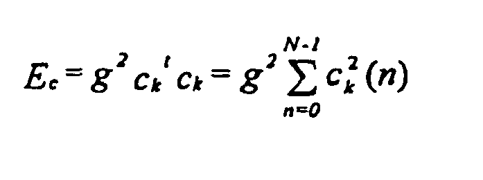
- Note that the value of rv lies between -1 and 1 (1 corresponds to purely voiced signals and -1 corresponds to purely unvoiced signals).
- In this preferred embodiment, the factor σ is then computed in voicing
factor generator 204 by
- In the first, two-term form of F(z), the periodicity factor σ can be approximated by using σ= 2α in
methods 1 and 2 above. In such a case, the periodicity factor σ is calculated as follows inmethod 1 above:
- In method 2, the periodicity factor σ is calculated as follows:

- The enhanced signal cf is therefore computed by filtering the scaled innovative codevector gck through the innovation filter 205 (F(z)).
- The enhanced excitation signal u' is computed by the
adder 220 as:
- Note that this process is not performed at the
encoder 100. Thus, it is essential to update the content of thepitch codebook 201 using the excitation signal u without enhancement to keep synchronism between theencoder 100 anddecoder 200. Therefore, the excitation signal u is used to update thememory 203 of thepitch codebook 201 and the enhanced excitation signal u' is used at the input of theLP synthesis filter 206. - The synthesized signal s' is computed by filtering the enhanced excitation signal u' through the
LP synthesis filter 206 which has theform 1/Â(z), where Â(z) is the interpolated LP filter in the current subframe. As can be seen in Figure 2, the quantized LP coefficients Â(z) online 225 fromdemultiplexer 217 are supplied to theLP synthesis filter 206 to adjust the parameters of theLP synthesis filter 206 accordingly. Thedeemphasis filter 207 is the inverse of thepreemphasis filter 103 of Figure 1. The transfer function of thedeemphasis filter 207 is given by
where: is a preemphasis factor with a value located between 0 and 1 (a typical value is : = 0.7). A higher-order filter could also be used. - The vector s' is filtered through the deemphasis filter D(z) (module 207) to obtain the vector sd, which is passed through the high-
pass filter 208 to remove the unwanted frequencies below 50 Hz and further obtain sh. - The
over-sampling module 209 conducts the inverse process of the down-sampling module 101 of Figure 1. In this preferred embodiment, oversampling converts from the 12.8 kHz sampling rate to the original 16 kHz sampling rate, using techniques well known to those of ordinary skill in the art. The oversampled synthesis signal is denoted Ŝ. Signal Ŝ is also referred to as the synthesized wideband intermediate signal. - The oversampled synthesis Ŝ signal does not contain the higher frequency components which were lost by the downsampling process (
module 101 of Figure 1) at theencoder 100. This gives a low-pass perception to the synthesized speech signal. To restore the full band of the original signal, a high frequency generation procedure is disclosed. This procedure is performed inmodules 210 to 216, andadder 221, and requires input from voicing factor generator 204 (Figure 2). - In this new approach, the high frequency contents are generated by filling the upper part of the spectrum with a white noise properly scaled in the excitation domain, then converted to the speech domain, preferably by shaping it with the same LP synthesis filter used for synthesizing the down-sampled signal Ŝ.
- The high frequency generation procedure is described hereinbelow.
- The
random noise generator 213 generates a white noise sequence w' with a flat spectrum over the entire frequency bandwidth, using techniques well known to those of ordinary skill in the art. The generated sequence has a length N' which is the subframe length in the original domain. Note that N is the subframe length in the down-sampled domain. In this preferred embodiment, N=64 and N'=80 which correspond to 5 ms. - The white noise sequence is properly scaled in the
gain adjusting module 214. Gain adjustment comprises the following steps. First, the energy of the generated noise sequence w' is set equal to the energy of the enhanced excitation signal u' computed by anenergy computing module 210, and the resulting scaled noise sequence is given by

- The second step in the gain scaling is to take into account the high frequency contents of the synthesized signal at the output of the voicing
factor generator 204 so as to reduce the energy of the generated noise in case of voiced segments (where less energy is present at high frequencies compared to unvoiced segments). In this preferred embodiment, measuring the high frequency contents is implemented by measuring the tilt of the synthesis signal through aspectral tilt calculator 212 and reducing the energy accordingly. Other measurements such as zero crossing measurements can equally be used. When the tilt is very strong, which corresponds to voiced segments, the noise energy is further reduced. The tilt factor is computed inmodule 212 as the first correlation coefficient of the synthesis signal sh and it is given by:
where voicing factor rv is given by
where Ev is the energy of the scaled pitch codevector bvT and Ec is the energy of the scaled innovative codevector gck, as described earlier. Voicing factor rv is most often less than tilt but this condition was introduced as a precaution against high frequency tones where the tilt value is negative and the value of rv is high. Therefore, this condition reduces the noise energy for such tonal signals. - The tilt value is 0 in case of flat spectrum and 1 in case of strongly voiced signals, and it is negative in case of unvoiced signals where more energy is present at high frequencies.
- Different methods can be used to derive the scaling factor gt from the amount of high frequency contents. In this invention, two methods are given based on the tilt of signal described above.
- The scaling factor gt is derived from the tilt by

- The tilt factor gt is first restricted to be larger or equal to zero, then the scaling factor is derived from the tilt by

- The scaled noise sequence wg produced in
gain adjusting module 214, is therefore given by:
- When the tilt is close to zero, the scaling factor gt is close to 1, which does not result in energy reduction. When the tilt value is 1, the scaling factor gt results in a reduction of 12 dB in the energy of the generated noise.
- Once the noise is properly scaled (wg), it is brought into the speech domain using the
spectral shaper 215. In the preferred embodiment, this is achieved by filtering the noise wg through a bandwidth expanded version of the same LP synthesis filter used in the down-sampled domain (1/Â(z/0.8)). The corresponding bandwidth expanded LP filter coefficients are calculated inspectral shaper 215. - The filtered scaled noise sequence wf is then band-pass filtered to the required frequency range to be restored using the band-
pass filter 216. In the preferred embodiment, the band-pass filter 216 restricts the noise sequence to the frequency range 5.6-7.2 kHz. The resulting band-pass filtered noise sequence z is added inadder 221 to the oversampled synthesized speech signal s' to obtain the final reconstructed sound signal sout on theoutput 223. - Although the present invention has been described hereinabove by way of a preferred embodiment thereof, this embodiment can be modified at will, within the scope of the appended claims. Even though the preferred embodiment discusses the use of wideband speech signals, it will be obvious to those skilled in the art that the subject invention is also directed to other embodiments using wideband signals in general and that it is not necessarily limited to speech applications.
Claims (92)
- A method for producing a gain-smoothed codevector during decoding of an encoded wideband signal from a set of signal encoding parameters, said method comprising:finding a codevector (ck) and a gain (g) in relation to at least one first (k) and at least one second (g) signal encoding parameters of said set;calculating (501, 502) a first factor (rv, λ) representative of a degree of voicing in the wideband signal in response to at least one third signal encoding parameter(b, vT) of said set;calculating (503, 504) a second factor (θ) representative of a degree of stability of said wideband signal in response to at least one fourth signal encoding parameter (LP) of said set;calculating a smoothed gain (gs) using a non linear operation related to the first and second factors (rv, λ; θ) and applied to the found gain (g) ; andamplifying the found codevector (ck) with said smoothed gain (gs) to thereby produce said gain-smoothed codevector.
- A gain-smoothed codevector producing method as claimed in claim 1, wherein:finding a codevector comprises finding an innovative codevector in an innovative codebook in relation to said at least one first signal encoding parameter; andfinding a gain comprises finding an innovative codebook gain.
- A gain-smoothed codevector producing method as claimed in claim 1, wherein:finding a codevector comprises finding a codevector in a codebook in relation to said at least one first signal encoding parameter; andsaid at least one first signal encoding parameter comprises an innovative codebook index.
- A gain-smoothed codevector producing method as claimed in claim 1, wherein:finding a codevector comprises finding an innovative codevector in an innovative codebook in relation to said at least one first signal encoding parameter; andsaid at least one third signal encoding parameter comprises the following parameters:a pitch gain computed during encoding of the wideband signal;a pitch delay computed during encoding of the wideband signal;an index j of a low-pass filter selected during encoding of the wideband signal and applied to a pitch codevector computed during encoding of the wideband signal; andan innovative codebook index computed during encoding of the wideband signal.
- A gain-smoothed codevector producing method as claimed in claim 1, wherein said at least one fourth signal encoding parameter comprises coefficients of a linear prediction filter calculated during encoding of the wideband signal.
- A gain-smoothed codevector producing method as claimed in claim 1, wherein:finding a codevector comprises finding an innovative codevector in an innovative codebook in relation to an index k of said innovative codebook, said index k forming said at least one first signal encoding parameter; andcalculating a first factor comprises computing a voicing factor rv by means of the following relation:where:
 - Ev is the energy of a scaled adaptive codevector bvT;- Ec is the energy of a scaled innovative codevector gck;- b is a pitch gain computed during encoding of the wideband signal;- T is a pitch delay computed during encoding of the wideband signal;- vT is an adaptive codebook vector at pitch delay T;- g is an innovative codebook gain computed during encoding of the wideband signal;- k is an index of the innovative codebook computed during encoding of the wideband signal; and- ck is the innovative codevector of said innovative codebook at index k.
 - A gain-smoothed codevector producing method as claimed in claim 6, wherein the voicing factor rv has a value located between -1 and 1, wherein value 1 corresponds to a pure voiced signal and value -1 corresponds to a pure unvoiced signal.
- A gain-smoothed codevector producing method as claimed in claim 7, wherein calculating a smoothed gain comprises computing a factor λ using the following relation:

- A gain-smoothed codevector producing method as claimed in claim 6, wherein a factor λ=0 indicates a pure voiced signal and a factor λ=1 indicates a pure unvoiced signal.
- A gain-smoothed codevector producing method as claimed in claim 1, wherein calculating a second factor comprises determining a distance measure giving a similarity between adjacent, successive linear prediction filters computed during encoding of the wideband signal.
- A gain-smoothed codevector producing method as claimed in claim 10, wherein:the wideband signal is sampled prior to encoding, and is processed by frames during encoding and decoding; anddetermining a distance measure comprises calculating an Immitance Spectral Pair distance measure between the Immitance Spectral Pairs in a present frame n of the wideband signal and the Immitance Spectral Pairs of a past frame n-1 of the wideband signal through the following relation:where p is the order of the linear prediction filters.

- A gain-smoothed codevector producing method as claimed in claim 11, wherein calculating a second factor comprises mapping the Immitance Spectral Pair distance measure Ds to said second factor θ through the following relation:

- A gain-smoothed codevector producing method as claimed in claim 1, wherein calculating a smoothed gain comprises calculating a gain smoothing factor Sm based on both the first λ and second θ factors through the following relation:

- A gain-smoothed codevector producing method as claimed in claim 13, wherein the factor Sm has a value approaching 1 for an unvoiced and stable wideband signal, and a value approaching 0 for a pure voiced wideband signal or an unstable wideband signal.
- A gain-smoothed codevector producing method as claimed in claim 1, wherein:finding a codevector comprises finding an innovative codevector in an innovative codebook in relation to said at least one first signal encoding parameter;the wideband signal is sampled prior to encoding, and is processed by frames and subframes during encoding and decoding; andcalculating a smoothed gain comprises computing an initial modified gain g0 by comparing the found gain g computed during encoding of the wideband signal to a threshold given by the initial modified gain from the past subframe g-1 as follows:


- A gain-smoothed codevector producing method as claimed in claim 1, wherein calculating a smoothed gain comprises calculating an initial modified gain g0 by comparing the found gain g to a threshold.
- A gain-smoothed codevector producing method as claimed in claim 16, wherein:calculating a smoothed gain comprises calculating a gain smoothing factor Sm based on both the first A and second θ factors through the following relation:


- A method for producing a gain-smoothed codevector during decoding of an encoded signal from a set of signal encoding parameters, said signal containing stationary background noise and said method comprising:finding a codevector (ck) and a gain (g) in relation to at least one first (k) and at least one second (g) signal encoding parameters of said set;calculating at least one factor (rv, λ; θ) indicative of a level of stationary background noise in the signal in response to at least one third signal encoding parameter (b, vT; LP) of said set;calculating a smoothed gain (gs) using a non linear operation related to the noise level indicative factor (rv, λ; θ) and applied to the found gain (g); andamplifying the found codevector (ck) with said smoothed gain (gs) to thereby produce said gain-smoothed codevector.
- A gain-smoothed codevector producing method as claimed in claim 18, wherein the at least one factor indicative of a level of stationary background noise is a factor (rv, λ) representative of a degree of voicing in the signal.
- A gain-smoothed codevector producing method as claimed in claim 18, wherein the at least one factor indicative of a level of stationary background noise is a factor (θ) representative of a degree of stability of said signal.
- A device for producing a gain-smoothed codevector during decoding of an encoded wideband signal from a set of signal encoding parameters, said device comprising:means for finding a codevector (ck) and a gain (g) in relation to at least one first (k) and at least one second (g) signal encoding parameters of said set;means for calculating (501, 502) a first factor (rv, λ) representative of a degree of voicing in the wideband signal in response to at least one third signal encoding parameter (b,vT) of said set;means for calculating (503, 504) a second factor (θ) representative of a degree of stability of said wideband signal in response to at least one fourth signal encoding parameter (LP) of said set;means for calculating a smoothed gain (gs) using a non linear operation related to the first and second factors (rv, λ; θ) and applied to the found gain (g); andmeans for amplifying the found codevector (ck) with said smoothed gain (gs) to thereby produce said gain-smoothed codevector.
- A gain-smoothed codevector producing device as claimed in claim 21, wherein:the means for finding a codevector and a gain comprises: means for finding an innovative codevector in an innovative codebook in relation to said at least one first signal encoding parameter; andmeans for finding an innovative codebook gain.
- A gain-smoothed codevector producing device as claimed in claim 21, wherein:the means for finding a codevector and a gain comprises means for finding a codevector in a codebook in relation to said at least one first signal encoding parameter; andsaid at least one first signal encoding parameter comprises an innovative codebook index.
- A gain-smoothed codevector producing device as claimed in claim 21, wherein:the means for finding a codevector and a gain comprises means for finding an innovative codevector in an innovative codebook in relation to said at least one first signal encoding parameter; andsaid at least one third signal encoding parameter comprises the following parameters:a pitch gain computed during encoding of the wideband signal;a pitch delay computed during encoding of the wideband signal;an index j of a low-pass filter selected during encoding of the wideband signal and applied to a pitch codevector computed during encoding of the wideband signal; andan innovative codebook index computed during encoding of the wideband signal.
- A gain-smoothed codevector producing device as claimed in claim 21, wherein said at least one fourth signal encoding parameter comprises coefficients of a linear prediction filter calculated during encoding of the wideband signal.
- A gain-smothed codevector producing device as claimed in claim 21, wherein:the means for finding a codevector and a gain comprises means for finding an innovative codevector in an innovative codebook in relation to an index k of said innovative codebook, said index k forming said at least one first signal encoding parameter; andthe means for calculating a first factor comprises means for computing a voicing factor rv by means of the following relation:where:
 - Ev is the energy of a scaled adaptive codevector bvT;- Ec is the energy of a scaled innovative codevector gck;- b is a pitch gain computed during encoding of the wideband signal;- T is a pitch delay computed during encoding of the wideband signal;- vT is an adaptive codebook vector at pitch delay T;- g is an innovative codebook gain computed during encoding of the wideband signal;- k is an index of the innovative codebook computed during encoding of the wideband signal; and- ck is the innovative codevector of said innovative codebook at index k.
 - A gain-smoothed codevector producing device as claimed in claim 26, wherein the voicing factor rv has a value located between -1 and 1, wherein value 1 corresponds to a pure voiced signal and value -1 corresponds to a pure unvoiced signal.
- A gain-smoothed codevector producing device as claimed in claim 27, wherein the means for calculating a smoothed gain comprises means for computing a factor λ using the following relation:

- A gain-smoothed codevector producing device as claimed in claim 28, wherein a factor λ=0 indicates a pure voiced signal and a factor λ=1 indicates a pure unvoiced signal.
- A gain-smoothed codevector producing device as claimed in claim 21, wherein the means for calculating a second factor comprises means for determining a distance measure giving a similarity between adjacent, successive linear prediction filters computed during encoding of the wideband signal.
- A gain-smoothed codevector producing device as claimed in claim 30, wherein:the wideband signal is sampled prior to encoding, and is processed by frames during encoding and decoding; andthe means for determining a distance measure comprises means for calculating an Immitance Spectral Pair distance measure between the Immitance Spectral Pairs in a present frame n of the wideband signal and the Immitance Spectral Pairs of a past frame n-1 of the wideband signal through the following relation:where p is the order of the linear prediction filters.

- A gain-smoothed codevector producing device as claimed in claim 31, wherein the means for calculating a second factor comprises means for mapping the Immitance Spectral Pair distance measure Ds to said second factor θ through the following relation:

- A gain-smoothed codevector producing device as claimed in claim 21, wherein the means for calculating a smoothed gain comprises means for calculating a gain smoothing factor Sm based on both the first λ and second θ factors through the following relation:

- A gain-smoothed codevector producing device as claimed in claim 33, wherein the factor Sm has a value approaching 1 for an unvoiced and stable wideband signal, and a value approaching 0 for a pure voiced wideband signal or an unstable wideband signal.
- A gain-smoothed codevector producing device as claimed in claim 21, wherein:the means for finding a codevector and a gain comprises means for finding an innovative codevector in an innovative codebook in relation to said at least one first signal encoding parameter;the wideband signal is sampled prior to encoding, and is processed by frames and subframes during encoding and decoding; andthe means for calculating a smoothed gain comprises means for computing an initial modified gain g0, said initial modified gain computing means comprising means for comparing the found gain g computed during encoding of the wideband signal to a threshold given by the initial modified gain from the past subframe g-1 as follows:


- A gain-smoothed codevector producing method as claimed in claim 21, wherein the means for calculating a smoothed gain comprises calculating an initial modified gain g0 by comparing the found gain g to a threshold.
- A gain-smoothed codevector producing method as claimed in claim 36, wherein:the means for calculating a smoothed gain comprises means for calculating a gain smoothing factor Sm based on both the first A and second θ factors through the following relation:


- A device for producing a gain-smoothed codevector during decoding of an encoded signal from a set of signal encoding parameters, said signal containing stationary background noise and said device comprising:means for finding a codevector (ck) and a gain (g) in relation to at least one first (k) and at least one second (g) signal encoding parameters of said set;means for calculating at least one factor (rv, λ; θ) indicative of a level of stationary background noise in the signal in response to at least one third signal encoding parameter (b, vT; LP) of said set;means for calculating a smoothed gain (gs) using a non linear operation related to the noise level indicative factor (rv, λ; θ) and applied to the found gain (g); andmeans for amplifying the found codevector (ck) with said smoothed gain (gs) to thereby produce said gain-smoothed codevector.
- A gain-smoothed codevector producing device as claimed in claim 38, wherein the at least one factor indicative of a level of stationary background noise is a factor (rv, λ) representative of a degree of voicing in the signal.
- A gain-smoothed codevector producing device as claimed in claim 38, wherein the at least one factor indicative of a level of stationary background noise is a factor (θ) representative of a degree of stability of said signal.
- A cellular communication system for servicing a geographical area divided into a plurality of cells, comprising:mobile transmitter/receiver units;cellular base stations respectively situated in said cells;means for controlling communication between the cellular base stations;a bidirectional wireless communication sub-system between each mobile unit situated in one cell and the cellular base station of said one cell, said bidirectional wireless communication sub-system comprising in both the mobile unit and the cellular base station (a) a transmitter including a decoder for encoding a wideband signal and means for transmitting the encoded wideband signal, and (b) a receiver including means for receiving a transmitted encoded wideband signal and a decoder for decoding the received encoded wideband signal;wherein said decoder comprises means responsive to a set of signal encoding parameters for decoding the received encoded wideband signal, and wherein said wideband signal decoding means comprises a device as recited in claim 21, for producing a gain-smoothed codevector during decoding of the encoded wideband signal from said set of signal encoding parameters.
- The cellular communication system of claim 41, wherein the means for finding a codevector and a gain comprises:means for finding an innovative codevector in an innovative codebook in relation to said at least one first signal encoding parameter; andmeans for finding an innovative codebook gain.
- The cellular communication system of claim 41, wherein:the means for finding a codevector and a gain comprises means for finding a codevector in a codebook in relation to said at least one first signal encoding parameter; andsaid at least one first signal encoding parameter comprises an innovative codebook index.
- The cellular communication system of claim 41, wherein:the means for finding a codevector and a gain comprises means for finding an innovative codevector in an innovative codebook in relation to said at least one first signal encoding parameter; andsaid at least one second signal encoding parameter comprises the following parameters:a pitch gain computed during encoding of the wideband signal;a pitch delay computed during encoding of the wideband signal;an index j of a low-pass filter selected during encoding of the wideband signal and applied to a pitch codevector computed during encoding of the wideband signal; andan innovative codebook index computed during encoding of the wideband signal.
- The cellular communication system of claim 41, wherein said at least one fourth signal encoding parameter comprises coefficients of a linear prediction filter calculated during encoding of the wideband signal.
- The cellular communication system of claim 41, wherein
the means for finding a codevector and a gain comprises means for finding an innovative codevector in an innovative codebook in relation to an index k of said innovative codebook, said index k forming said at least one first signal encoding parameter; and
the means for calculating a first factor comprises means for computing a voicing factor rv by means of the following relation:
where:- Ev is the energy of a scaled adaptive codevector bvT;- Ec is the energy of a scaled innovative codevector gck;- b is a pitch gain computed during encoding of the wideband signal;- T is a pitch delay computed during encoding of the wideband signal;- vT is an adaptive codebook vector at pitch delay T;- g is an innovative codebook gain computed during encoding of the wideband signal;- k is an index of the innovative codebook computed during encoding of the wideband signal; and- ck is the innovative codevector of said innovative codebook at index k. - The cellular communication system of claim 46, wherein the voicing factor rv has a value located between -1 and 1, wherein value 1 corresponds to a pure voiced signal and value -1 corresponds to a pure unvoiced signals.
- The cellular communication system of claim 47, wherein the means for calculating a smoothed gain comprises means for computing a factor λ using the following relation:

- The cellular communication system of claim 48, wherein a factor λ=0 indicates a pure voiced signal and a factor λ=1 indicates a pure unvoiced signal.
- The cellular communication system of claim 41, wherein the means for calculating a second factor comprises means for determining a distance measure giving a similarity between adjacent, successive linear prediction filters computed during encoding of the wideband signal.
- The cellular communication system of claim 50, wherein:the wideband signal is sampled prior to encoding, and is processed by frames during encoding and decoding; andthe means for determining a distance measure comprises means for calculating an Immitance Spectral Pair distance measure between the Immitance Spectral Pairs in a present frame n of the wideband signal and the Immitance Spectral Pairs of a past frame n-1 of the wideband signal through the following relation:where p is the order of the linear prediction filters.
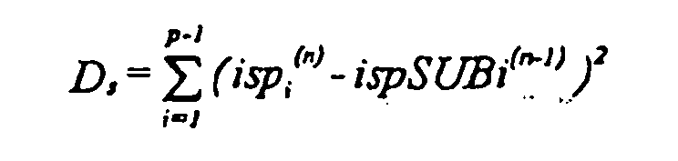
- The cellular communication system of claim 51, wherein the means for calculating a second factor comprises means for mapping the Immitance Spectral Pair distance measure Ds to said second factor θ through the following relation:

- The cellular communication system of claim 41, wherein the means for calculating a smoothed gain comprises means for calculating a gain smoothing factor Sm based on both the first λ and second θ factors through the following relation:

- The cellular communication system of claim 53, wherein the factor Sm has a value approaching 1 for an unvoiced and stable wideband signal, and a value approaching 0 for a pure voiced wideband signal or an unstable wideband signal.
- The cellular communication system of claim 41, wherein:the means for finding a codevector and a gain comprises means for finding an innovative codevector in an innovative codebook in relation to said at least one first signal encoding parameter;the wideband signal is sampled prior to encoding, and is processed by frames and subframes during encoding and decoding; andthe means for calculating a smoothed gain comprises means for computing an initial modified gain g0, said initial modified gain computing means comprising means for comparing the found gain g computed during encoding of the wideband signal to a threshold given by the initial modified gain from the past subframe g-1 as follows:


- The cellular communication system of claim 41, wherein the means for calculating a smoothed gain comprises calculating an initial modified gain g0 by comparing the found gain g to a threshold.
- The cellular communication system of claim 56, wherein:the means for calculating a smoothed gain comprises means for calculating a gain smoothing factor Sm based on both the first λ and second θ factors through the following relation:
 and means for determining said smoothed gain gs through the following relation:
- A network element comprising a receiver including means for receiving a transmitted encoded wideband signal and a decoder for decoding the received encoded wideband signal;
wherein said decoder comprises means responsive to a set of signal encoding parameters for decoding the received encoded wideband signal, and wherein said wideband signal decoding means comprises a device as recited in claim 21, for producing a gain-smoothed codevector during decoding of the encoded wideband signal from said set of signal encoding parameters. - A network element as claimed in claim 58, wherein the means for finding a codevector and a gain comprises:means for finding an innovative codevector in an innovative codebook in relation to said at least one first signal encoding parameter; andmeans for finding an innovative codebook gain.
- A network element as claimed in claim 58, wherein:the means for finding a codevector and a gain comprises means for finding a codevector in a codebook in relation to said at least one first signal encoding parameter; andsaid at least one first signal encoding parameter comprises an innovative codebook index.
- A network element as claimed in claim 58, wherein:the means for finding a codevector and a gain comprises means for finding an innovative codevector in an innovative codebook in relation to said at least one first signal encoding parameter; andsaid at least one third signal encoding parameter comprises the following parameters:a pitch gain computed during encoding of the wideband signal;a pitch delay computed during encoding of the wideband signal;an index j of a low-pass filter selected during encoding of the wideband signal and applied to a pitch codevector computed during encoding of the wideband signal; andan innovative codebook index computed during encoding of the wideband signal.
- A network element as claimed in claim 58, wherein said at least one fourth signal encoding parameter comprises coefficients of a linear prediction filter calculated during encoding of the wideband signal.
- A network element as claimed in claim 58, wherein:the means for finding a codevector and a gain comprises means for finding an innovative codevector in an innovative codebook in relation to an index k of said innovative codebook, said index k forming said at least one first signal encoding parameter; andthe means for calculating a first factor comprises means for computing a voicing factor rv by means of the following relation:where:
 - Ev is the energy of a scaled adaptive codevector bvT;- Ec is the energy of a scaled innovative codevector gck;- b is a pitch gain computed during encoding of the wideband signal;- T is a pitch delay computed during encoding of the wideband signal;- vT is an adaptive codebook vector at pitch delay T;- g is an innovative codebook gain computed during encoding of the wideband signal;- k is an index of the innovative codebook computed during encoding of the wideband signal; and- ck is the innovative codevector of said innovative codebook at index k.
 - A network element as claimed in claim 63, wherein the voicing factor rv has a value located between -1 and 1, wherein value 1 corresponds to a pure voiced signal and value -1 corresponds to a pure unvoiced signals.
- A network element as claimed in claim 64, wherein the means for calculating a smoothed gain comprises means for computing a factor λ using the following relation:

- A network element as claimed in claim 65, wherein a factor λ=0 indicates a pure voiced signal and a factor λ=1 indicates a pure unvoiced signal.
- A network element as claimed in claim 58, wherein the means for calculating a second factor comprises means for determining a distance measure giving a similarity between adjacent, successive linear prediction filters computed during encoding of the wideband signal.
- A network element as claimed in claim 67, wherein:the wideband signal is sampled prior to encoding, and is processed by frames during encoding and decoding; andthe means for determining a distance measure comprises means for calculating an Immitance Spectral Pair distance measure between the Immitance Spectral Pairs in a present frame n of the wideband signal and the Immitance Spectral Pairs of a past frame n-1 of the wideband signal through the following relation:where p is the order of the linear prediction filters.

- A network element as claimed in claim 68, wherein the means for calculating a second factor comprises means for mapping the Immitance Spectral Pair distance measure Ds to said second factor θ through the following relation:

- A network element as claimed in claim 58, wherein the means for calculating a smoothed gain comprises means for calculating a gain smoothing factor Sm based on both the first λ and second θ factors through the following relation:

- A network element as claimed in claim 70, wherein the factor Sm has a value approaching 1 for an unvoiced and stable wideband signal, and a value approaching 0 for a pure voiced wideband signal or an unstable wideband signal.
- A network element as claimed in claim 58, wherein:the means for finding a codevector and a gain comprises means for finding an innovative codevector in an innovative codebook in relation to said at least one first signal encoding parameter;the wideband signal is sampled prior to encoding, and is processed by frames and subframes during encoding and decoding; andthe means for calculating a smoothed gain comprises means for computing an initial modified gain go, said initial modified gain computing means comprising means for comparing the found gain g computed during encoding of the wideband signal to a threshold given by the initial modified gain from the past subframe g-1 as follows:


- A network element as claimed in claim 58, wherein the means for calculating a smoothed gain comprises calculating an initial modified gain g0 by comparing the found gain g to a threshold.
- A network element as claimed in claim 73, wherein:the means for calculating a smoothed gain comprises means for calculating gain smoothing factor Sm based on the first λ and second θ factors through the following relation:
 and means for determining said smoothing gain gs through the following relation:
- In a communication system for servicing a geographical area, comprising mobile transmitter/receiver units and base stations, a bidirectional wireless communication sub-system between each pair of mobile unit and base station, said bidirectional wireless communication sub-system comprising in both the mobile unit and the base station (a) a transmitter including an encoder for encoding a wideband signal and means for transmitting the encoded wideband signal, and (b) a receiver including means for receiving a transmitted encoded wideband signal and a decoder for decoding the received encoded wideband signal;
wherein said decoder comprises means responsive to a set of signal encoding parameters for decoding the received encoded wideband signal, and wherein said wideband signal decoding means comprises a device as recited in claim 21, for producing a gain-smoothed codevector during decoding of the encoded wideband signal from said set of signal encoding parameters. - The bidirectional wireless communication sub-system of claim 75, wherein the means for finding a codevector comprises:means for finding an innovative codevector in an innovative codebook in relation to said at least one first signal encoding parameter; andmeans for finding an innovative codebook gain.
- The bidirectional wireless communication sub-system of claim 75, wherein:the means for finding a codevector and a gain comprises means for finding a codevector in a codebook in relation to said at least one first signal encoding parameter; andsaid at least one first signal encoding parameter comprises an innovative codebook index.
- The bidirectional wireless communication sub-system of claim 75, wherein:the means for finding a codevector and a gain comprises means for finding an innovative codevector in an innovative codebook in relation to said at least one first signal encoding parameter; andsaid at least one third signal encoding parameter comprises the following parameters:a pitch gain computed during encoding of the wideband signal;a pitch delay computed during encoding of the wideband signal;an index j of a low-pass filter selected during encoding of the wideband signal and applied to a pitch codevector computed during encoding of the wideband signal; andan innovative codebook index computed during encoding of the wideband signal.
- The bidirectional wireless communication sub-system claim 75, wherein said at least one fourth signal encoding parameter comprises coefficients of a linear prediction filter calculated during encoding of the wideband signal.
- The bidirectional wireless communication sub-system as claimed in claim 75, wherein:the means for finding a codevector comprises means for finding an innovative codevector in an innovative codebook in relation to an index k of said innovative codebook, said index k forming said at least one first signal encoding parameter; andthe means for calculating a first factor comprises means for computing a voicing factor rv by means of the following relation:where:
 - Ev is the energy of a scaled adaptive codevector bvT;- Ec is the energy of a scaled innovative codevector gck;- b is a pitch gain computed during encoding of the wideband signal;- T is a pitch delay computed during encoding of the wideband signal;- vT is an adaptive codebook vector at pitch delay T;- g is an innovative codebook gain computed during encoding of the wideband signal;- k is an index of the innovative codebook computed during encoding of the wideband signal; and- ck is the innovative codevector of said innovative codebook at index k.
 - The bidirectional wireless communication sub-system of claim 80, wherein the voicing factor rv has a value located between -1 and 1, wherein value 1 corresponds to a pure voiced signal and value -1 corresponds to a pure unvoiced signals.
- The bidirectional wireless communication sub-system of claim 80, wherein the means for calculating a smoothed gain comprises means for computing a factor λ using the following relation:

- The bidirectional wireless communication sub-system of claim 82, wherein a factor λ=0 indicates a pure voiced signal and a factor λ=1 indicates a pure unvoiced signal.
- The bidirectional wireless communication sub-system of claim 75, wherein the means for calculating a second factor comprises means for determining a distance measure giving a similarity between adjacent, successive linear prediction filters computed during encoding of the wideband signal.
- The bidirectional wireless communication sub-system of claim 84, wherein:the wideband signal is sampled prior to encoding, and is processed by frames during encoding and decoding; andthe means for determining a distance measure comprises means for calculating an Immitance Spectral Pair distance measure between the Immitance Spectral Pairs in a present frame n of the wideband signal and the Immitance Spectral Pairs of a past frame n-1 of the wideband signal through the following relation:where p is the order of the linear prediction filters.

- The bidirectional wireless communication sub-system of claim 85, wherein the means for calculating a second factor comprises means for mapping the Immitance Spectral Pair distance measure Ds to said second factor θ through the following relation:

- The bidirectional wireless communication sub-system of claim 75, wherein the means for calculating a smoothing gain comprises means for calculating a gain smoothing factor Sm based on both the first λ and second θ factors through the following relation:

- The bidirectional wireless communication sub-system of claim 87, wherein the factor Sm has a value approaching 1 for an unvoiced and stable wideband signal, and a value approaching 0 for a pure voiced wideband signal or an unstable wideband signal.
- The bidirectional wireless communication sub-system of claim 75, wherein:the means for finding a codevector comprises means for finding an innovative codevector in an innovative codebook in relation to said at least one first signal encoding parameter;the wideband signal is sampled prior to encoding, and is processed by frames and subframes during encoding and decoding; andthe means for calculating a smoothed gain comprises means for computing an initial modified gain go, said initial modified gain computing means comprising means for comparing the found gain g computed during encoding of the wideband signal.to a threshold given by the initial modified gain from the past subframe g-1 as follows:


- The bidirectional wireless communication sub-system of claim 75, wherein the means for calculating a smoothed gain comprises calculating an initial modified gain g0 by comparing the found gain g to a threshold.
- The bidirectional wireless communication sub-system of claim 90, wherein: the means for calculating a smoothed gain comprises means for calculating a gain smoothing factor Sm based on both the first λ and second θ factors through the following relation:


- A mobile telephone including a device according to claim 21.
Applications Claiming Priority (3)
| Application Number | Priority Date | Filing Date | Title |
|---|---|---|---|
| CA2290037 | 1999-11-18 | ||
| CA002290037A CA2290037A1 (en) | 1999-11-18 | 1999-11-18 | Gain-smoothing amplifier device and method in codecs for wideband speech and audio signals |
| PCT/CA2000/001381 WO2001037264A1 (en) | 1999-11-18 | 2000-11-17 | Gain-smoothing in wideband speech and audio signal decoder |
Publications (2)
| Publication Number | Publication Date |
|---|---|
| EP1232494A1 EP1232494A1 (en) | 2002-08-21 |
| EP1232494B1 true EP1232494B1 (en) | 2006-08-09 |
Family
ID=4164645
Family Applications (1)
| Application Number | Title | Priority Date | Filing Date |
|---|---|---|---|
| EP00978928A Expired - Lifetime EP1232494B1 (en) | 1999-11-18 | 2000-11-17 | Gain-smoothing in wideband speech and audio signal decoder |
Country Status (13)
| Country | Link |
|---|---|
| US (1) | US7191123B1 (en) |
| EP (1) | EP1232494B1 (en) |
| JP (1) | JP4662673B2 (en) |
| CN (1) | CN1229775C (en) |
| AT (1) | ATE336060T1 (en) |
| AU (1) | AU1644401A (en) |
| CA (1) | CA2290037A1 (en) |
| CY (1) | CY1106164T1 (en) |
| DE (1) | DE60029990T2 (en) |
| DK (1) | DK1232494T3 (en) |
| ES (1) | ES2266003T3 (en) |
| PT (1) | PT1232494E (en) |
| WO (1) | WO2001037264A1 (en) |
Cited By (2)
| Publication number | Priority date | Publication date | Assignee | Title |
|---|---|---|---|---|
| US7890322B2 (en) | 2008-03-20 | 2011-02-15 | Huawei Technologies Co., Ltd. | Method and apparatus for speech signal processing |
| CN101609674B (en) * | 2008-06-20 | 2011-12-28 | 华为技术有限公司 | Method, device and system for coding and decoding |
Families Citing this family (39)
| Publication number | Priority date | Publication date | Assignee | Title |
|---|---|---|---|---|
| SE0202159D0 (en) | 2001-07-10 | 2002-07-09 | Coding Technologies Sweden Ab | Efficientand scalable parametric stereo coding for low bitrate applications |
| US8605911B2 (en) | 2001-07-10 | 2013-12-10 | Dolby International Ab | Efficient and scalable parametric stereo coding for low bitrate audio coding applications |
| DE60202881T2 (en) | 2001-11-29 | 2006-01-19 | Coding Technologies Ab | RECONSTRUCTION OF HIGH-FREQUENCY COMPONENTS |
| SE0202770D0 (en) | 2002-09-18 | 2002-09-18 | Coding Technologies Sweden Ab | Method of reduction of aliasing is introduced by spectral envelope adjustment in real-valued filterbanks |
| KR100480341B1 (en) * | 2003-03-13 | 2005-03-31 | 한국전자통신연구원 | Apparatus for coding wide-band low bit rate speech signal |
| JP4390803B2 (en) * | 2003-05-01 | 2009-12-24 | ノキア コーポレイション | Method and apparatus for gain quantization in variable bit rate wideband speech coding |
| US7451091B2 (en) | 2003-10-07 | 2008-11-11 | Matsushita Electric Industrial Co., Ltd. | Method for determining time borders and frequency resolutions for spectral envelope coding |
| CA2454296A1 (en) * | 2003-12-29 | 2005-06-29 | Nokia Corporation | Method and device for speech enhancement in the presence of background noise |
| CN101116137B (en) * | 2005-02-10 | 2011-02-09 | 松下电器产业株式会社 | Pulse allocating method in voice coding |
| NZ562182A (en) * | 2005-04-01 | 2010-03-26 | Qualcomm Inc | Method and apparatus for anti-sparseness filtering of a bandwidth extended speech prediction excitation signal |
| TWI324336B (en) * | 2005-04-22 | 2010-05-01 | Qualcomm Inc | Method of signal processing and apparatus for gain factor smoothing |
| DE102005032724B4 (en) * | 2005-07-13 | 2009-10-08 | Siemens Ag | Method and device for artificially expanding the bandwidth of speech signals |
| CN100420155C (en) * | 2005-08-03 | 2008-09-17 | 上海杰得微电子有限公司 | Frequency band partition method for broad band acoustic frequency compression encoder |
| US8260620B2 (en) * | 2006-02-14 | 2012-09-04 | France Telecom | Device for perceptual weighting in audio encoding/decoding |
| US8195454B2 (en) * | 2007-02-26 | 2012-06-05 | Dolby Laboratories Licensing Corporation | Speech enhancement in entertainment audio |
| ES2394515T3 (en) * | 2007-03-02 | 2013-02-01 | Telefonaktiebolaget Lm Ericsson (Publ) | Methods and adaptations in a telecommunications network |
| CN101266798B (en) * | 2007-03-12 | 2011-06-15 | 华为技术有限公司 | A method and device for gain smoothing in voice decoder |
| DE102008009719A1 (en) * | 2008-02-19 | 2009-08-20 | Siemens Enterprise Communications Gmbh & Co. Kg | Method and means for encoding background noise information |
| US8831936B2 (en) | 2008-05-29 | 2014-09-09 | Qualcomm Incorporated | Systems, methods, apparatus, and computer program products for speech signal processing using spectral contrast enhancement |
| US8538749B2 (en) | 2008-07-18 | 2013-09-17 | Qualcomm Incorporated | Systems, methods, apparatus, and computer program products for enhanced intelligibility |
| US9202456B2 (en) | 2009-04-23 | 2015-12-01 | Qualcomm Incorporated | Systems, methods, apparatus, and computer-readable media for automatic control of active noise cancellation |
| JP5754899B2 (en) | 2009-10-07 | 2015-07-29 | ソニー株式会社 | Decoding apparatus and method, and program |
| KR101761629B1 (en) | 2009-11-24 | 2017-07-26 | 엘지전자 주식회사 | Audio signal processing method and device |
| JP5850216B2 (en) | 2010-04-13 | 2016-02-03 | ソニー株式会社 | Signal processing apparatus and method, encoding apparatus and method, decoding apparatus and method, and program |
| US9053697B2 (en) | 2010-06-01 | 2015-06-09 | Qualcomm Incorporated | Systems, methods, devices, apparatus, and computer program products for audio equalization |
| JP6075743B2 (en) | 2010-08-03 | 2017-02-08 | ソニー株式会社 | Signal processing apparatus and method, and program |
| JP5707842B2 (en) | 2010-10-15 | 2015-04-30 | ソニー株式会社 | Encoding apparatus and method, decoding apparatus and method, and program |
| CN103295578B (en) | 2012-03-01 | 2016-05-18 | 华为技术有限公司 | A kind of voice frequency signal processing method and device |
| KR101398189B1 (en) * | 2012-03-27 | 2014-05-22 | 광주과학기술원 | Speech receiving apparatus, and speech receiving method |
| US9728200B2 (en) * | 2013-01-29 | 2017-08-08 | Qualcomm Incorporated | Systems, methods, apparatus, and computer-readable media for adaptive formant sharpening in linear prediction coding |
| JP6531649B2 (en) | 2013-09-19 | 2019-06-19 | ソニー株式会社 | Encoding apparatus and method, decoding apparatus and method, and program |
| JP5981408B2 (en) * | 2013-10-29 | 2016-08-31 | 株式会社Nttドコモ | Audio signal processing apparatus, audio signal processing method, and audio signal processing program |
| CN105745706B (en) * | 2013-11-29 | 2019-09-24 | 索尼公司 | Device, methods and procedures for extending bandwidth |
| BR112016014476B1 (en) | 2013-12-27 | 2021-11-23 | Sony Corporation | DECODING APPARATUS AND METHOD, AND, COMPUTER-READABLE STORAGE MEANS |
| GB201401689D0 (en) * | 2014-01-31 | 2014-03-19 | Microsoft Corp | Audio signal processing |
| CA2940657C (en) | 2014-04-17 | 2021-12-21 | Voiceage Corporation | Methods, encoder and decoder for linear predictive encoding and decoding of sound signals upon transition between frames having different sampling rates |
| US9510787B2 (en) * | 2014-12-11 | 2016-12-06 | Mitsubishi Electric Research Laboratories, Inc. | Method and system for reconstructing sampled signals |
| US10847170B2 (en) | 2015-06-18 | 2020-11-24 | Qualcomm Incorporated | Device and method for generating a high-band signal from non-linearly processed sub-ranges |
| US9837089B2 (en) * | 2015-06-18 | 2017-12-05 | Qualcomm Incorporated | High-band signal generation |
Family Cites Families (14)
| Publication number | Priority date | Publication date | Assignee | Title |
|---|---|---|---|---|
| US5701392A (en) | 1990-02-23 | 1997-12-23 | Universite De Sherbrooke | Depth-first algebraic-codebook search for fast coding of speech |
| US5754976A (en) | 1990-02-23 | 1998-05-19 | Universite De Sherbrooke | Algebraic codebook with signal-selected pulse amplitude/position combinations for fast coding of speech |
| CA2010830C (en) | 1990-02-23 | 1996-06-25 | Jean-Pierre Adoul | Dynamic codebook for efficient speech coding based on algebraic codes |
| US5195168A (en) * | 1991-03-15 | 1993-03-16 | Codex Corporation | Speech coder and method having spectral interpolation and fast codebook search |
| JP3186412B2 (en) * | 1994-04-01 | 2001-07-11 | ソニー株式会社 | Information encoding method, information decoding method, and information transmission method |
| US5651090A (en) * | 1994-05-06 | 1997-07-22 | Nippon Telegraph And Telephone Corporation | Coding method and coder for coding input signals of plural channels using vector quantization, and decoding method and decoder therefor |
| US5664055A (en) * | 1995-06-07 | 1997-09-02 | Lucent Technologies Inc. | CS-ACELP speech compression system with adaptive pitch prediction filter gain based on a measure of periodicity |
| US5960386A (en) * | 1996-05-17 | 1999-09-28 | Janiszewski; Thomas John | Method for adaptively controlling the pitch gain of a vocoder's adaptive codebook |
| JP3707153B2 (en) * | 1996-09-24 | 2005-10-19 | ソニー株式会社 | Vector quantization method, speech coding method and apparatus |
| TW326070B (en) * | 1996-12-19 | 1998-02-01 | Holtek Microelectronics Inc | The estimation method of the impulse gain for coding vocoder |
| US5987406A (en) * | 1997-04-07 | 1999-11-16 | Universite De Sherbrooke | Instability eradication for analysis-by-synthesis speech codecs |
| US6453289B1 (en) * | 1998-07-24 | 2002-09-17 | Hughes Electronics Corporation | Method of noise reduction for speech codecs |
| US6240386B1 (en) * | 1998-08-24 | 2001-05-29 | Conexant Systems, Inc. | Speech codec employing noise classification for noise compensation |
| US6260010B1 (en) * | 1998-08-24 | 2001-07-10 | Conexant Systems, Inc. | Speech encoder using gain normalization that combines open and closed loop gains |
-
1999
- 1999-11-18 CA CA002290037A patent/CA2290037A1/en not_active Abandoned
-
2000
- 2000-11-17 ES ES00978928T patent/ES2266003T3/en not_active Expired - Lifetime
- 2000-11-17 PT PT00978928T patent/PT1232494E/en unknown
- 2000-11-17 AU AU16444/01A patent/AU1644401A/en not_active Abandoned
- 2000-11-17 US US10/129,945 patent/US7191123B1/en not_active Expired - Lifetime
- 2000-11-17 DE DE60029990T patent/DE60029990T2/en not_active Expired - Lifetime
- 2000-11-17 JP JP2001537726A patent/JP4662673B2/en not_active Expired - Lifetime
- 2000-11-17 WO PCT/CA2000/001381 patent/WO2001037264A1/en active IP Right Grant
- 2000-11-17 EP EP00978928A patent/EP1232494B1/en not_active Expired - Lifetime
- 2000-11-17 CN CNB008158541A patent/CN1229775C/en not_active Expired - Lifetime
- 2000-11-17 DK DK00978928T patent/DK1232494T3/en active
- 2000-11-17 AT AT00978928T patent/ATE336060T1/en active
-
2006
- 2006-09-20 CY CY20061101344T patent/CY1106164T1/en unknown
Cited By (2)
| Publication number | Priority date | Publication date | Assignee | Title |
|---|---|---|---|---|
| US7890322B2 (en) | 2008-03-20 | 2011-02-15 | Huawei Technologies Co., Ltd. | Method and apparatus for speech signal processing |
| CN101609674B (en) * | 2008-06-20 | 2011-12-28 | 华为技术有限公司 | Method, device and system for coding and decoding |
Also Published As
| Publication number | Publication date |
|---|---|
| EP1232494A1 (en) | 2002-08-21 |
| PT1232494E (en) | 2006-10-31 |
| JP4662673B2 (en) | 2011-03-30 |
| DE60029990T2 (en) | 2006-12-07 |
| WO2001037264A1 (en) | 2001-05-25 |
| CN1229775C (en) | 2005-11-30 |
| DE60029990D1 (en) | 2006-09-21 |
| ATE336060T1 (en) | 2006-09-15 |
| CY1106164T1 (en) | 2011-06-08 |
| DK1232494T3 (en) | 2006-11-13 |
| JP2003514267A (en) | 2003-04-15 |
| CA2290037A1 (en) | 2001-05-18 |
| CN1391689A (en) | 2003-01-15 |
| AU1644401A (en) | 2001-05-30 |
| US7191123B1 (en) | 2007-03-13 |
| ES2266003T3 (en) | 2007-03-01 |
Similar Documents
| Publication | Publication Date | Title |
|---|---|---|
| EP1232494B1 (en) | Gain-smoothing in wideband speech and audio signal decoder | |
| US6807524B1 (en) | Perceptual weighting device and method for efficient coding of wideband signals |
Legal Events
| Date | Code | Title | Description |
|---|---|---|---|
| PUAI | Public reference made under article 153(3) epc to a published international application that has entered the european phase |
Free format text: ORIGINAL CODE: 0009012 |
|
| 17P | Request for examination filed |
Effective date: 20020514 |
|
| AK | Designated contracting states |
Kind code of ref document: A1 Designated state(s): AT BE CH CY DE DK ES FI FR GB GR IE IT LI LU MC NL PT SE TR |
|
| AX | Request for extension of the european patent |
Free format text: AL;LT;LV;MK;RO;SI |
|
| 17Q | First examination report despatched |
Effective date: 20040415 |
|
| GRAP | Despatch of communication of intention to grant a patent |
Free format text: ORIGINAL CODE: EPIDOSNIGR1 |
|
| GRAS | Grant fee paid |
Free format text: ORIGINAL CODE: EPIDOSNIGR3 |
|
| GRAA | (expected) grant |
Free format text: ORIGINAL CODE: 0009210 |
|
| AK | Designated contracting states |
Kind code of ref document: B1 Designated state(s): AT BE CH CY DE DK ES FI FR GB GR IE IT LI LU MC NL PT SE TR |
|
| PG25 | Lapsed in a contracting state [announced via postgrant information from national office to epo] |
Ref country code: IT Free format text: LAPSE BECAUSE OF FAILURE TO SUBMIT A TRANSLATION OF THE DESCRIPTION OR TO PAY THE FEE WITHIN THE PRESCRIBED TIME-LIMIT;WARNING: LAPSES OF ITALIAN PATENTS WITH EFFECTIVE DATE BEFORE 2007 MAY HAVE OCCURRED AT ANY TIME BEFORE 2007. THE CORRECT EFFECTIVE DATE MAY BE DIFFERENT FROM THE ONE RECORDED. Effective date: 20060809 |
|
| REG | Reference to a national code |
Ref country code: GB Ref legal event code: FG4D |
|
| REG | Reference to a national code |
Ref country code: CH Ref legal event code: EP |
|
| REG | Reference to a national code |
Ref country code: IE Ref legal event code: FG4D |
|
| REG | Reference to a national code |
Ref country code: SE Ref legal event code: TRGR |
|
| REF | Corresponds to: |
Ref document number: 60029990 Country of ref document: DE Date of ref document: 20060921 Kind code of ref document: P |
|
| REG | Reference to a national code |
Ref country code: CH Ref legal event code: NV Representative=s name: PATENTANWAELTE SCHAAD, BALASS, MENZL & PARTNER AG |
|
| REG | Reference to a national code |
Ref country code: PT Ref legal event code: SC4A Effective date: 20060830 |
|
| REG | Reference to a national code |
Ref country code: GR Ref legal event code: EP Ref document number: 20060403104 Country of ref document: GR |
|
| REG | Reference to a national code |
Ref country code: DK Ref legal event code: T3 |
|
| ET | Fr: translation filed | ||
| REG | Reference to a national code |
Ref country code: ES Ref legal event code: FG2A Ref document number: 2266003 Country of ref document: ES Kind code of ref document: T3 |
|
| PLBE | No opposition filed within time limit |
Free format text: ORIGINAL CODE: 0009261 |
|
| STAA | Information on the status of an ep patent application or granted ep patent |
Free format text: STATUS: NO OPPOSITION FILED WITHIN TIME LIMIT |
|
| 26N | No opposition filed |
Effective date: 20070510 |
|
| PG25 | Lapsed in a contracting state [announced via postgrant information from national office to epo] |
Ref country code: TR Free format text: LAPSE BECAUSE OF FAILURE TO SUBMIT A TRANSLATION OF THE DESCRIPTION OR TO PAY THE FEE WITHIN THE PRESCRIBED TIME-LIMIT Effective date: 20060809 |
|
| PG25 | Lapsed in a contracting state [announced via postgrant information from national office to epo] |
Ref country code: CY Free format text: LAPSE BECAUSE OF NON-PAYMENT OF DUE FEES Effective date: 20101117 |
|
| REG | Reference to a national code |
Ref country code: DE Ref legal event code: R082 Ref document number: 60029990 Country of ref document: DE Representative=s name: BOSCH JEHLE PATENTANWALTSGESELLSCHAFT MBH, DE |
|
| REG | Reference to a national code |
Ref country code: DE Ref legal event code: R079 Ref document number: 60029990 Country of ref document: DE Free format text: PREVIOUS MAIN CLASS: G10L0019140000 Ipc: G10L0019040000 |
|
| REG | Reference to a national code |
Ref country code: DE Ref legal event code: R079 Ref document number: 60029990 Country of ref document: DE Free format text: PREVIOUS MAIN CLASS: G10L0019040000 Ipc: G10L0019120000 |
|
| REG | Reference to a national code |
Ref country code: DE Ref legal event code: R079 Ref document number: 60029990 Country of ref document: DE Free format text: PREVIOUS MAIN CLASS: G10L0019140000 Ipc: G10L0019040000 Effective date: 20140801 Ref country code: DE Ref legal event code: R081 Ref document number: 60029990 Country of ref document: DE Owner name: SAINT LAWRENCE COMMUNICATIONS GMBH, DE Free format text: FORMER OWNER: VOICEAGE CORP., VILLE MONT-ROYAL, QUEBEC, CA Effective date: 20140701 Ref country code: DE Ref legal event code: R079 Ref document number: 60029990 Country of ref document: DE Free format text: PREVIOUS MAIN CLASS: G10L0019040000 Ipc: G10L0019120000 Effective date: 20140802 Ref country code: DE Ref legal event code: R082 Ref document number: 60029990 Country of ref document: DE Representative=s name: BOSCH JEHLE PATENTANWALTSGESELLSCHAFT MBH, DE Effective date: 20140701 |
|
| REG | Reference to a national code |
Ref country code: DE Ref legal event code: R008 Ref document number: 60029990 Country of ref document: DE Ref country code: DE Ref legal event code: R039 Ref document number: 60029990 Country of ref document: DE |
|
| REG | Reference to a national code |
Ref country code: DE Ref legal event code: R097 Ref document number: 60029990 Country of ref document: DE Ref country code: DE Ref legal event code: R040 Ref document number: 60029990 Country of ref document: DE |
|
| REG | Reference to a national code |
Ref country code: DE Ref legal event code: R039 Ref document number: 60029990 Country of ref document: DE Effective date: 20150126 |
|
| REG | Reference to a national code |
Ref country code: FR Ref legal event code: PLFP Year of fee payment: 16 |
|
| REG | Reference to a national code |
Ref country code: DE Ref legal event code: R008 Ref document number: 60029990 Country of ref document: DE Ref country code: DE Ref legal event code: R039 Ref document number: 60029990 Country of ref document: DE |
|
| REG | Reference to a national code |
Ref country code: FR Ref legal event code: PLFP Year of fee payment: 17 |
|
| REG | Reference to a national code |
Ref country code: DE Ref legal event code: R040 Ref document number: 60029990 Country of ref document: DE Ref country code: DE Ref legal event code: R097 Ref document number: 60029990 Country of ref document: DE |
|
| REG | Reference to a national code |
Ref country code: FR Ref legal event code: PLFP Year of fee payment: 18 |
|
| REG | Reference to a national code |
Ref country code: DE Ref legal event code: R040 Ref document number: 60029990 Country of ref document: DE |
|
| PGFP | Annual fee paid to national office [announced via postgrant information from national office to epo] |
Ref country code: CY Payment date: 20181113 Year of fee payment: 19 |
|
| PGFP | Annual fee paid to national office [announced via postgrant information from national office to epo] |
Ref country code: LU Payment date: 20191028 Year of fee payment: 20 |
|
| PGFP | Annual fee paid to national office [announced via postgrant information from national office to epo] |
Ref country code: DE Payment date: 20191028 Year of fee payment: 20 Ref country code: SE Payment date: 20191118 Year of fee payment: 20 Ref country code: MC Payment date: 20191111 Year of fee payment: 20 Ref country code: NL Payment date: 20191028 Year of fee payment: 20 Ref country code: FI Payment date: 20191028 Year of fee payment: 20 Ref country code: IE Payment date: 20191118 Year of fee payment: 20 |
|
| PGFP | Annual fee paid to national office [announced via postgrant information from national office to epo] |
Ref country code: BE Payment date: 20191126 Year of fee payment: 20 Ref country code: GR Payment date: 20191029 Year of fee payment: 20 Ref country code: ES Payment date: 20191209 Year of fee payment: 20 Ref country code: DK Payment date: 20191030 Year of fee payment: 20 Ref country code: FR Payment date: 20191129 Year of fee payment: 20 Ref country code: IT Payment date: 20191024 Year of fee payment: 20 |
|
| PGFP | Annual fee paid to national office [announced via postgrant information from national office to epo] |
Ref country code: AT Payment date: 20191028 Year of fee payment: 20 Ref country code: CH Payment date: 20191030 Year of fee payment: 20 |
|
| PGFP | Annual fee paid to national office [announced via postgrant information from national office to epo] |
Ref country code: GB Payment date: 20191031 Year of fee payment: 20 |
|
| PG25 | Lapsed in a contracting state [announced via postgrant information from national office to epo] |
Ref country code: CY Free format text: LAPSE BECAUSE OF NON-PAYMENT OF DUE FEES Effective date: 20191117 |
|
| REG | Reference to a national code |
Ref country code: DE Ref legal event code: R071 Ref document number: 60029990 Country of ref document: DE |
|
| REG | Reference to a national code |
Ref country code: NL Ref legal event code: MK Effective date: 20201116 |
|
| REG | Reference to a national code |
Ref country code: DK Ref legal event code: EUP Expiry date: 20201117 |
|
| REG | Reference to a national code |
Ref country code: CH Ref legal event code: PL |
|
| REG | Reference to a national code |
Ref country code: GB Ref legal event code: PE20 Expiry date: 20201116 |
|
| REG | Reference to a national code |
Ref country code: FI Ref legal event code: MAE |
|
| REG | Reference to a national code |
Ref country code: IE Ref legal event code: MK9A |
|
| REG | Reference to a national code |
Ref country code: AT Ref legal event code: MK07 Ref document number: 336060 Country of ref document: AT Kind code of ref document: T Effective date: 20201117 Ref country code: BE Ref legal event code: MK Effective date: 20201117 |
|
| PG25 | Lapsed in a contracting state [announced via postgrant information from national office to epo] |
Ref country code: IE Free format text: LAPSE BECAUSE OF EXPIRATION OF PROTECTION Effective date: 20201117 Ref country code: GB Free format text: LAPSE BECAUSE OF EXPIRATION OF PROTECTION Effective date: 20201116 Ref country code: PT Free format text: LAPSE BECAUSE OF EXPIRATION OF PROTECTION Effective date: 20201126 |
|
| REG | Reference to a national code |
Ref country code: ES Ref legal event code: FD2A Effective date: 20210226 |
|
| PG25 | Lapsed in a contracting state [announced via postgrant information from national office to epo] |
Ref country code: ES Free format text: LAPSE BECAUSE OF EXPIRATION OF PROTECTION Effective date: 20201118 |