US6260010B1 - Speech encoder using gain normalization that combines open and closed loop gains - Google Patents
Speech encoder using gain normalization that combines open and closed loop gains Download PDFInfo
- Publication number
- US6260010B1 US6260010B1 US09/156,650 US15665098A US6260010B1 US 6260010 B1 US6260010 B1 US 6260010B1 US 15665098 A US15665098 A US 15665098A US 6260010 B1 US6260010 B1 US 6260010B1
- Authority
- US
- United States
- Prior art keywords
- normalization factor
- gain
- speech
- gain normalization
- loop gain
- Prior art date
- Legal status (The legal status is an assumption and is not a legal conclusion. Google has not performed a legal analysis and makes no representation as to the accuracy of the status listed.)
- Expired - Lifetime
Links
- 238000010606 normalization Methods 0.000 title claims abstract description 110
- 238000000034 method Methods 0.000 claims abstract description 48
- 239000013598 vector Substances 0.000 claims description 127
- 230000003044 adaptive effect Effects 0.000 claims description 123
- 238000012545 processing Methods 0.000 claims description 100
- 230000005284 excitation Effects 0.000 claims description 84
- 238000004891 communication Methods 0.000 abstract description 26
- 238000009499 grossing Methods 0.000 abstract description 21
- 238000003786 synthesis reaction Methods 0.000 description 48
- 230000015572 biosynthetic process Effects 0.000 description 42
- 238000013139 quantization Methods 0.000 description 30
- 238000004458 analytical method Methods 0.000 description 24
- 238000001914 filtration Methods 0.000 description 23
- 238000013459 approach Methods 0.000 description 22
- 230000004044 response Effects 0.000 description 22
- 230000003595 spectral effect Effects 0.000 description 22
- 238000010586 diagram Methods 0.000 description 21
- 230000007774 longterm Effects 0.000 description 19
- 238000007781 pre-processing Methods 0.000 description 18
- 230000008569 process Effects 0.000 description 15
- 230000006870 function Effects 0.000 description 10
- 239000011159 matrix material Substances 0.000 description 10
- 230000015654 memory Effects 0.000 description 10
- 238000012986 modification Methods 0.000 description 9
- 230000004048 modification Effects 0.000 description 9
- 230000001934 delay Effects 0.000 description 8
- 238000012937 correction Methods 0.000 description 6
- 238000001228 spectrum Methods 0.000 description 6
- 238000005070 sampling Methods 0.000 description 5
- 101100194363 Schizosaccharomyces pombe (strain 972 / ATCC 24843) res2 gene Proteins 0.000 description 4
- 238000006243 chemical reaction Methods 0.000 description 4
- 230000000694 effects Effects 0.000 description 4
- 230000009467 reduction Effects 0.000 description 4
- 230000011664 signaling Effects 0.000 description 4
- 238000004364 calculation method Methods 0.000 description 3
- 230000001413 cellular effect Effects 0.000 description 3
- 238000001514 detection method Methods 0.000 description 3
- 238000005457 optimization Methods 0.000 description 3
- 238000012805 post-processing Methods 0.000 description 3
- 230000001755 vocal effect Effects 0.000 description 3
- 230000006978 adaptation Effects 0.000 description 2
- 230000008901 benefit Effects 0.000 description 2
- 230000005540 biological transmission Effects 0.000 description 2
- 230000008859 change Effects 0.000 description 2
- 238000011045 prefiltration Methods 0.000 description 2
- 238000012857 repacking Methods 0.000 description 2
- 238000012546 transfer Methods 0.000 description 2
- 230000009286 beneficial effect Effects 0.000 description 1
- 230000015556 catabolic process Effects 0.000 description 1
- 238000006731 degradation reaction Methods 0.000 description 1
- 230000003111 delayed effect Effects 0.000 description 1
- 235000019800 disodium phosphate Nutrition 0.000 description 1
- 238000011156 evaluation Methods 0.000 description 1
- 238000000695 excitation spectrum Methods 0.000 description 1
- 230000002349 favourable effect Effects 0.000 description 1
- 239000000835 fiber Substances 0.000 description 1
- 238000010348 incorporation Methods 0.000 description 1
- 238000012886 linear function Methods 0.000 description 1
- 230000000873 masking effect Effects 0.000 description 1
- 230000003287 optical effect Effects 0.000 description 1
- 230000036961 partial effect Effects 0.000 description 1
- 230000000135 prohibitive effect Effects 0.000 description 1
- 230000002829 reductive effect Effects 0.000 description 1
- 230000000717 retained effect Effects 0.000 description 1
- 238000000638 solvent extraction Methods 0.000 description 1
- 230000001360 synchronised effect Effects 0.000 description 1
- 230000002194 synthesizing effect Effects 0.000 description 1
- 230000009466 transformation Effects 0.000 description 1
Images
Classifications
-
- G—PHYSICS
- G10—MUSICAL INSTRUMENTS; ACOUSTICS
- G10L—SPEECH ANALYSIS TECHNIQUES OR SPEECH SYNTHESIS; SPEECH RECOGNITION; SPEECH OR VOICE PROCESSING TECHNIQUES; SPEECH OR AUDIO CODING OR DECODING
- G10L19/00—Speech or audio signals analysis-synthesis techniques for redundancy reduction, e.g. in vocoders; Coding or decoding of speech or audio signals, using source filter models or psychoacoustic analysis
- G10L19/005—Correction of errors induced by the transmission channel, if related to the coding algorithm
-
- G—PHYSICS
- G10—MUSICAL INSTRUMENTS; ACOUSTICS
- G10L—SPEECH ANALYSIS TECHNIQUES OR SPEECH SYNTHESIS; SPEECH RECOGNITION; SPEECH OR VOICE PROCESSING TECHNIQUES; SPEECH OR AUDIO CODING OR DECODING
- G10L19/00—Speech or audio signals analysis-synthesis techniques for redundancy reduction, e.g. in vocoders; Coding or decoding of speech or audio signals, using source filter models or psychoacoustic analysis
- G10L19/012—Comfort noise or silence coding
-
- G—PHYSICS
- G10—MUSICAL INSTRUMENTS; ACOUSTICS
- G10L—SPEECH ANALYSIS TECHNIQUES OR SPEECH SYNTHESIS; SPEECH RECOGNITION; SPEECH OR VOICE PROCESSING TECHNIQUES; SPEECH OR AUDIO CODING OR DECODING
- G10L19/00—Speech or audio signals analysis-synthesis techniques for redundancy reduction, e.g. in vocoders; Coding or decoding of speech or audio signals, using source filter models or psychoacoustic analysis
- G10L19/04—Speech or audio signals analysis-synthesis techniques for redundancy reduction, e.g. in vocoders; Coding or decoding of speech or audio signals, using source filter models or psychoacoustic analysis using predictive techniques
- G10L19/08—Determination or coding of the excitation function; Determination or coding of the long-term prediction parameters
- G10L19/083—Determination or coding of the excitation function; Determination or coding of the long-term prediction parameters the excitation function being an excitation gain
-
- G—PHYSICS
- G10—MUSICAL INSTRUMENTS; ACOUSTICS
- G10L—SPEECH ANALYSIS TECHNIQUES OR SPEECH SYNTHESIS; SPEECH RECOGNITION; SPEECH OR VOICE PROCESSING TECHNIQUES; SPEECH OR AUDIO CODING OR DECODING
- G10L19/00—Speech or audio signals analysis-synthesis techniques for redundancy reduction, e.g. in vocoders; Coding or decoding of speech or audio signals, using source filter models or psychoacoustic analysis
- G10L19/04—Speech or audio signals analysis-synthesis techniques for redundancy reduction, e.g. in vocoders; Coding or decoding of speech or audio signals, using source filter models or psychoacoustic analysis using predictive techniques
- G10L19/08—Determination or coding of the excitation function; Determination or coding of the long-term prediction parameters
- G10L19/10—Determination or coding of the excitation function; Determination or coding of the long-term prediction parameters the excitation function being a multipulse excitation
-
- G—PHYSICS
- G10—MUSICAL INSTRUMENTS; ACOUSTICS
- G10L—SPEECH ANALYSIS TECHNIQUES OR SPEECH SYNTHESIS; SPEECH RECOGNITION; SPEECH OR VOICE PROCESSING TECHNIQUES; SPEECH OR AUDIO CODING OR DECODING
- G10L19/00—Speech or audio signals analysis-synthesis techniques for redundancy reduction, e.g. in vocoders; Coding or decoding of speech or audio signals, using source filter models or psychoacoustic analysis
- G10L19/04—Speech or audio signals analysis-synthesis techniques for redundancy reduction, e.g. in vocoders; Coding or decoding of speech or audio signals, using source filter models or psychoacoustic analysis using predictive techniques
- G10L19/08—Determination or coding of the excitation function; Determination or coding of the long-term prediction parameters
- G10L19/12—Determination or coding of the excitation function; Determination or coding of the long-term prediction parameters the excitation function being a code excitation, e.g. in code excited linear prediction [CELP] vocoders
- G10L19/125—Pitch excitation, e.g. pitch synchronous innovation CELP [PSI-CELP]
-
- G—PHYSICS
- G10—MUSICAL INSTRUMENTS; ACOUSTICS
- G10L—SPEECH ANALYSIS TECHNIQUES OR SPEECH SYNTHESIS; SPEECH RECOGNITION; SPEECH OR VOICE PROCESSING TECHNIQUES; SPEECH OR AUDIO CODING OR DECODING
- G10L19/00—Speech or audio signals analysis-synthesis techniques for redundancy reduction, e.g. in vocoders; Coding or decoding of speech or audio signals, using source filter models or psychoacoustic analysis
- G10L19/04—Speech or audio signals analysis-synthesis techniques for redundancy reduction, e.g. in vocoders; Coding or decoding of speech or audio signals, using source filter models or psychoacoustic analysis using predictive techniques
- G10L19/16—Vocoder architecture
- G10L19/18—Vocoders using multiple modes
-
- G—PHYSICS
- G10—MUSICAL INSTRUMENTS; ACOUSTICS
- G10L—SPEECH ANALYSIS TECHNIQUES OR SPEECH SYNTHESIS; SPEECH RECOGNITION; SPEECH OR VOICE PROCESSING TECHNIQUES; SPEECH OR AUDIO CODING OR DECODING
- G10L19/00—Speech or audio signals analysis-synthesis techniques for redundancy reduction, e.g. in vocoders; Coding or decoding of speech or audio signals, using source filter models or psychoacoustic analysis
- G10L19/04—Speech or audio signals analysis-synthesis techniques for redundancy reduction, e.g. in vocoders; Coding or decoding of speech or audio signals, using source filter models or psychoacoustic analysis using predictive techniques
- G10L19/26—Pre-filtering or post-filtering
- G10L19/265—Pre-filtering, e.g. high frequency emphasis prior to encoding
-
- G—PHYSICS
- G10—MUSICAL INSTRUMENTS; ACOUSTICS
- G10L—SPEECH ANALYSIS TECHNIQUES OR SPEECH SYNTHESIS; SPEECH RECOGNITION; SPEECH OR VOICE PROCESSING TECHNIQUES; SPEECH OR AUDIO CODING OR DECODING
- G10L21/00—Speech or voice signal processing techniques to produce another audible or non-audible signal, e.g. visual or tactile, in order to modify its quality or its intelligibility
- G10L21/02—Speech enhancement, e.g. noise reduction or echo cancellation
- G10L21/0316—Speech enhancement, e.g. noise reduction or echo cancellation by changing the amplitude
- G10L21/0364—Speech enhancement, e.g. noise reduction or echo cancellation by changing the amplitude for improving intelligibility
-
- G—PHYSICS
- G10—MUSICAL INSTRUMENTS; ACOUSTICS
- G10L—SPEECH ANALYSIS TECHNIQUES OR SPEECH SYNTHESIS; SPEECH RECOGNITION; SPEECH OR VOICE PROCESSING TECHNIQUES; SPEECH OR AUDIO CODING OR DECODING
- G10L19/00—Speech or audio signals analysis-synthesis techniques for redundancy reduction, e.g. in vocoders; Coding or decoding of speech or audio signals, using source filter models or psychoacoustic analysis
- G10L19/002—Dynamic bit allocation
-
- G—PHYSICS
- G10—MUSICAL INSTRUMENTS; ACOUSTICS
- G10L—SPEECH ANALYSIS TECHNIQUES OR SPEECH SYNTHESIS; SPEECH RECOGNITION; SPEECH OR VOICE PROCESSING TECHNIQUES; SPEECH OR AUDIO CODING OR DECODING
- G10L19/00—Speech or audio signals analysis-synthesis techniques for redundancy reduction, e.g. in vocoders; Coding or decoding of speech or audio signals, using source filter models or psychoacoustic analysis
- G10L19/04—Speech or audio signals analysis-synthesis techniques for redundancy reduction, e.g. in vocoders; Coding or decoding of speech or audio signals, using source filter models or psychoacoustic analysis using predictive techniques
- G10L19/08—Determination or coding of the excitation function; Determination or coding of the long-term prediction parameters
- G10L19/09—Long term prediction, i.e. removing periodical redundancies, e.g. by using adaptive codebook or pitch predictor
-
- G—PHYSICS
- G10—MUSICAL INSTRUMENTS; ACOUSTICS
- G10L—SPEECH ANALYSIS TECHNIQUES OR SPEECH SYNTHESIS; SPEECH RECOGNITION; SPEECH OR VOICE PROCESSING TECHNIQUES; SPEECH OR AUDIO CODING OR DECODING
- G10L19/00—Speech or audio signals analysis-synthesis techniques for redundancy reduction, e.g. in vocoders; Coding or decoding of speech or audio signals, using source filter models or psychoacoustic analysis
- G10L2019/0001—Codebooks
- G10L2019/0004—Design or structure of the codebook
- G10L2019/0005—Multi-stage vector quantisation
-
- G—PHYSICS
- G10—MUSICAL INSTRUMENTS; ACOUSTICS
- G10L—SPEECH ANALYSIS TECHNIQUES OR SPEECH SYNTHESIS; SPEECH RECOGNITION; SPEECH OR VOICE PROCESSING TECHNIQUES; SPEECH OR AUDIO CODING OR DECODING
- G10L19/00—Speech or audio signals analysis-synthesis techniques for redundancy reduction, e.g. in vocoders; Coding or decoding of speech or audio signals, using source filter models or psychoacoustic analysis
- G10L2019/0001—Codebooks
- G10L2019/0007—Codebook element generation
-
- G—PHYSICS
- G10—MUSICAL INSTRUMENTS; ACOUSTICS
- G10L—SPEECH ANALYSIS TECHNIQUES OR SPEECH SYNTHESIS; SPEECH RECOGNITION; SPEECH OR VOICE PROCESSING TECHNIQUES; SPEECH OR AUDIO CODING OR DECODING
- G10L19/00—Speech or audio signals analysis-synthesis techniques for redundancy reduction, e.g. in vocoders; Coding or decoding of speech or audio signals, using source filter models or psychoacoustic analysis
- G10L2019/0001—Codebooks
- G10L2019/0011—Long term prediction filters, i.e. pitch estimation
Definitions
- a microfiche appendix is included in the application of 1 slide and 24 frames.
- the present invention relates generally to speech encoding and decoding in voice communication systems; and, more particularly, it relates to various techniques used with code-excited linear prediction coding to obtain high quality speech reproduction through a limited bit rate communication channel.
- LPC linear predictive coding
- a conventional source encoder operates on speech signals to extract modeling and parameter information for communication to a conventional source decoder via a communication channel. Once received, the decoder attempts to reconstruct a counterpart signal for playback that sounds to a human ear like the original speech.
- a certain amount of communication channel bandwidth is required to communicate the modeling and parameter information to the decoder.
- a reduction in the required bandwidth proves beneficial.
- the quality requirements in the reproduced speech limit the reduction of such bandwidth below certain levels.
- the speech encoding system has an encoder processing circuit and a plurality of codebooks that generate excitation vectors.
- the encoder processing circuit calculates open loop gain and closed loop gain.
- the encoder processing circuit selectively applies the open and closed loop gains in gain normalization processing.
- the selective application of the open loop gain and the closed loop gain by the encoder processing circuit may further involve the use of a weighting factor of linear predictive coding gain.
- the encoder processing circuit may use weighting factor to linearly combine the open and closed loop gains.
- the selective application of the open and closed loop gains by the encoder processing circuit comprises applying the lesser of the open loop gain and the closed loop gain to the background noise.
- the encoder processing circuit may exclude such background noise from the application of the weighting factor.
- the encoder processing circuit may apply a maximum limit, a minimum limit, or both in gain normalization processing.
- such method may further involve the use of linear predictive coding gain to identify appropriate contributions of the open and closed loop gains.
- linear predictive coding gain may be used as a weighting factor.
- the encoder processing system may also select without combination either the open loop gain or the closed loop gain in generating the gain normalization factor. In some cases, this involves selection of the lesser of the open loop gain and the closed loop gain.
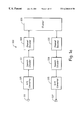
- FIG. 1 a is a schematic block diagram of a speech communication system illustrating the use of source encoding and decoding in accordance with the present invention.
- FIG. 1 b is a schematic block diagram illustrating an exemplary communication device utilizing the source encoding and decoding functionality of FIG. 1 a.
- FIGS. 2-4 are functional block diagrams illustrating a multi-step encoding approach used by one embodiment of the speech encoder illustrated in FIGS. 1 a and 1 b .
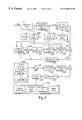
- FIG. 2 is a functional block diagram illustrating of a first stage of operations performed by one embodiment of the speech encoder of FIGS. 1 a and 1 b .
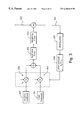
- FIG. 3 is a functional block diagram of a second stage of operations, while FIG. 4 illustrates a third stage.
- FIG. 5 is a block diagram of one embodiment of the speech decoder shown in FIGS. 1 a and 1 b having corresponding functionality to that illustrated in FIGS. 2-4.
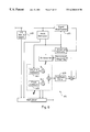
- FIG. 6 is a block diagram of an alternate embodiment of a speech encoder that is built in accordance with the present invention.
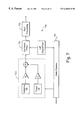
- FIG. 7 is a block diagram of an embodiment of a speech decoder having corresponding functionality to that of the speech encoder of FIG. 6 .
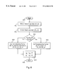
- FIG. 8 is a flow diagram illustrating the functionality of gain normalization such as that represented in the block 401 of FIG. 4 by an encoder built in accordance with the present invention.
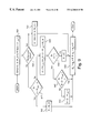
- FIG. 9 is a flow diagram providing a more detailed description of one embodiment of gain normalization functionality of FIG. 8 .
- FIG. 1 a is a schematic block diagram of a speech communication system illustrating the use of source encoding and decoding in accordance with the present invention.
- a speech communication system 100 supports communication and reproduction of speech across a communication channel 103 .
- the communication channel 103 typically comprises, at least in part, a radio frequency link that often must support multiple, simultaneous speech exchanges requiring shared bandwidth resources such as may be found with cellular telephony embodiments.
- a storage device may be coupled to the communication channel 103 to temporarily store speech information for delayed reproduction or playback, e.g., to perform answering machine functionality, voiced email, etc.
- the communication channel 103 might be replaced by such a storage device in a single device embodiment of the communication system 100 that, for example, merely records and stores speech for subsequent playback.
- a microphone 111 produces a speech signal in real time.
- the microphone 111 delivers the speech signal to an A/D (analog to digital) converter 115 .
- the A/D converter 115 converts the speech signal to a digital form then delivers the digitized speech signal to a speech encoder 117 .
- the speech encoder 117 encodes the digitized speech by using a selected one of a plurality of encoding modes. Each of the plurality of encoding modes utilizes particular techniques that attempt to optimize quality of resultant reproduced speech. While operating in any of the plurality of modes, the speech encoder 117 produces a series of modeling and parameter information (hereinafter “speech indices”), and delivers the speech indices to a channel encoder 119 .
- speech indices modeling and parameter information
- the channel encoder 119 coordinates with a channel decoder 131 to deliver the speech indices across the communication channel 103 .
- the channel decoder 131 forwards the speech indices to a speech decoder 133 .
- the speech decoder 133 While operating in a mode that corresponds to that of the speech encoder 117 , the speech decoder 133 attempts to recreate the original speech from the speech indices as accurately as possible at a speaker 137 via a D/A (digital to analog) converter 135 .
- the speech encoder 117 adaptively selects one of the plurality of operating modes based on the data rate restrictions through the communication channel 103 .
- the communication channel 103 comprises a bandwidth allocation between the channel encoder 119 and the channel decoder 131 .
- the allocation is established, for example, by telephone switching networks wherein many such channels are allocated and reallocated as need arises. In one such embodiment, either a 22.8 kbps (kilobits per second) channel bandwidth, i.e., a full rate channel, or a 11.4 kbps channel bandwidth, i.e., a half rate channel, may be allocated.
- the speech encoder 117 may adaptively select an encoding mode that supports a bit rate of 11.0, 8.0, 6.65 or 5.8 kbps.
- the speech encoder 117 adaptively selects an either 8.0, 6.65, 5.8 or 4.5 kbps encoding bit rate mode when only the half rate channel has been allocated.
- these encoding bit rates and the aforementioned channel allocations are only representative of the present embodiment. Other variations to meet the goals of alternate embodiments are contemplated.
- the speech encoder 117 attempts to communicate using the highest encoding bit rate mode that the allocated channel will support. If the allocated channel is or becomes noisy or otherwise restrictive to the highest or higher encoding bit rates, the speech encoder 117 adapts by selecting a lower bit rate encoding mode. Similarly, when the communication channel 103 becomes more favorable, the speech encoder 117 adapts by switching to a higher bit rate encoding mode.
- the speech encoder 117 incorporates various techniques to generate better low bit rate speech reproduction. Many of the techniques applied are based on characteristics of the speech itself. For example, with lower bit rate encoding, the speech encoder 117 classifies noise, unvoiced speech, and voiced speech so that an appropriate modeling scheme corresponding to a particular classification can be selected and implemented. Thus, the speech encoder 117 adaptively selects from among a plurality of modeling schemes those most suited for the current speech. The speech encoder 117 also applies various other techniques to optimize the modeling as set forth in more detail below.
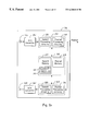
- FIG. 1 b is a schematic block diagram illustrating several variations of an exemplary communication device employing the functionality of FIG. 1 a .
- a communication device 151 comprises both a speech encoder and decoder for simultaneous capture and reproduction of speech.
- the communication device 151 might, for example, comprise a cellular telephone, portable telephone, computing system, etc.
- the communication device 151 might, for example, comprise a cellular telephone, portable telephone, computing system, etc.
- the communication device 151 might comprise an answering machine, a recorder, voice mail system, etc.
- a microphone 155 and an A/D converter 157 coordinate to deliver a digital voice signal to an encoding system 159 .
- the encoding system 159 performs speech and channel encoding and delivers resultant speech information to the channel.
- the delivered speech information may be destined for another communication device (not shown) at a remote location.
- a decoding system 165 performs channel and speech decoding then coordinates with a D/A converter 167 and a speaker 169 to reproduce something that sounds like the originally captured speech.
- the encoding system 159 comprises both a speech processing circuit 185 that performs speech encoding, and a channel processing circuit 187 that performs channel encoding.
- the decoding system 165 comprises a speech processing circuit 189 that performs speech decoding, and a channel processing circuit 191 that performs channel decoding.
- the speech processing circuit 185 and the channel processing circuit 187 are separately illustrated, they might be combined in part or in total into a single unit.
- the speech processing circuit 185 and the channel processing circuitry 187 might share a single DSP (digital signal processor) and/or other processing circuitry.
- the speech processing circuit 189 and the channel processing circuit 191 might be entirely separate or combined in part or in whole.
- combinations in whole or in part might be applied to the speech processing circuits 185 and 189 , the channel processing circuits 187 and 191 , the processing circuits 185 , 187 , 189 and 191 , or otherwise.
- the encoding system 159 and the decoding system 165 both utilize a memory 161 .
- the speech processing circuit 185 utilizes a fixed codebook 181 and an adaptive codebook 183 of a speech memory 177 in the source encoding process.
- the channel processing circuit 187 utilizes a channel memory 175 to perform channel encoding.
- the speech processing circuit 189 utilizes the fixed codebook 181 and the adaptive codebook 183 in the source decoding process.
- the channel processing circuit 187 utilizes the channel memory 175 to perform channel decoding.
- the speech memory 177 is shared as illustrated, separate copies thereof can be assigned for the processing circuits 185 and 189 . Likewise, separate channel memory can be allocated to both the processing circuits 187 and 191 .
- the memory 161 also contains software utilized by the processing circuits 185 , 187 , 189 and 191 to perform various functionality required in the source and channel encoding and decoding processes.
- FIGS. 2-4 are functional block diagrams illustrating a multi-step encoding approach used by one embodiment of the speech encoder illustrated in FIGS. 1 a and 1 b .
- FIG. 2 is a functional block diagram illustrating of a first stage of operations performed by one embodiment of the speech encoder shown in FIGS. 1 a and 1 b .
- the speech encoder which comprises encoder processing circuitry, typically operates pursuant to software instruction carrying out the following functionality.
- source encoder processing circuitry performs high pass filtering of a speech signal 211 .
- the filter uses a cutoff frequency of around 80 Hz to remove, for example, 60 Hz power line noise and other lower frequency signals.
- the source encoder processing circuitry applies a perceptual weighting filter as represented by a block 219 .
- the perceptual weighting filter operates to emphasize the valley areas of the filtered speech signal.
- a pitch preprocessing operation is performed on the weighted speech signal at a block 225 .
- the pitch preprocessing operation involves warping the weighted speech signal to match interpolated pitch values that will be generated by the decoder processing circuitry.
- the warped speech signal is designated a first target signal 229 . If pitch preprocessing is not selected the control block 245 , the weighted speech signal passes through the block 225 without pitch preprocessing and is designated the first target signal 229 .
- the encoder processing circuitry applies a process wherein a contribution from an adaptive codebook 257 is selected along with a corresponding gain 257 which minimize a first error signal 253 .
- the first error signal 253 comprises the difference between the first target signal 229 and a weighted, synthesized contribution from the adaptive codebook 257 .
- the resultant excitation vector is applied after adaptive gain reduction to both a synthesis and a weighting filter to generate a modeled signal that best matches the first target signal 229 .
- the encoder processing circuitry uses LPC (linear predictive coding) analysis, as indicated by a block 239 , to generate filter parameters for the synthesis and weighting filters.
- LPC linear predictive coding
- the encoder processing circuitry designates the first error signal 253 as a second target signal for matching using contributions from a fixed codebook 261 .
- the encoder processing circuitry searches through at least one of the plurality of subcodebooks within the fixed codebook 261 in an attempt to select a most appropriate contribution while generally attempting to match the second target signal.
- the encoder processing circuitry selects an excitation vector, its corresponding subcodebook and gain based on a variety of factors. For example, the encoding bit rate, the degree of minimization, and characteristics of the speech itself as represented by a block 279 are considered by the encoder processing circuitry at control block 275 . Although many other factors may be considered, exemplary characteristics include speech classification, noise level, sharpness, periodicity, etc. Thus, by considering other such factors, a first subcodebook with its best excitation vector may be selected rather than a second subcodebook's best excitation vector even though the second subcodebook's better minimizes the second target signal 265 .
- FIG. 3 is a functional block diagram depicting of a second stage of operations performed by the embodiment of the speech encoder illustrated in FIG. 2 .
- the speech encoding circuitry simultaneously uses both the adaptive the fixed codebook vectors found in the first stage of operations to minimize a third error signal 311 .
- the speech encoding circuitry searches for optimum gain values for the previously identified excitation vectors (in the first stage) from both the adaptive and fixed codebooks 257 and 261 . As indicated by blocks 307 and 309 , the speech encoding circuitry identifies the optimum gain by generating a synthesized and weighted signal, i.e., via a block 301 and 303 , that best matches the first target signal 229 (which minimizes the third error signal 311 ). Of course if processing capabilities permit, the first and second stages could be combined wherein joint optimization of both gain and adaptive and fixed codebook rector selection could be used.
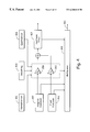
- FIG. 4 is a functional block diagram depicting of a third stage of operations performed by the embodiment of the speech encoder illustrated in FIGS. 2 and 3.
- the encoder processing circuitry applies gain normalization, smoothing and quantization, as represented by blocks 401 , 403 and 405 , respectively, to the jointly optimized gains identified in the second stage of encoder processing.
- the adaptive and fixed codebook vectors used are those identified in the first stage processing.
- the encoder processing circuitry With normalization, smoothing and quantization functionally applied, the encoder processing circuitry has completed the modeling process. Therefore, the modeling parameters identified are communicated to the decoder.
- the encoder processing circuitry delivers an index to the selected adaptive codebook vector to the channel encoder via a multiplexor 419 .
- the encoder processing circuitry delivers the index to the selected fixed codebook vector, resultant gains, synthesis filter parameters, etc., to the muliplexor 419 .
- the multiplexor 419 generates a bit stream 421 of such information for delivery to the channel encoder for communication to the channel and speech decoder of receiving device.
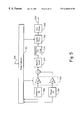
- FIG. 5 is a block diagram of an embodiment illustrating functionality of speech decoder having corresponding functionality to that illustrated in FIGS. 2-4.
- the speech decoder which comprises decoder processing circuitry, typically operates pursuant to software instruction carrying out the following functionality.
- a demultiplexor 511 receives a bit stream 513 of speech modeling indices from an often remote encoder via a channel decoder. As previously discussed, the encoder selected each index value during the multi-stage encoding process described above in reference to FIGS. 2-4.
- the decoder processing circuitry utilizes indices, for example, to select excitation vectors from an adaptive codebook 515 and a fixed codebook 519 , set the adaptive and fixed codebook gains at a block 521 , and set the parameters for a synthesis filter 531 .
- the decoder processing circuitry With such parameters and vectors selected or set, the decoder processing circuitry generates a reproduced speech signal 539 .
- the codebooks 515 and 519 generate excitation vectors identified by the indices from the demultiplexor 511 .
- the decoder processing circuitry applies the indexed gains at the block 521 to the vectors which are summed.
- the decoder processing circuitry modifies the gains to emphasize the contribution of vector from the adaptive codebook 515 .
- adaptive tilt compensation is applied to the combined vectors with a goal of flattening the excitation spectrum.
- the decoder processing circuitry performs synthesis filtering at the block 531 using the flattened excitation signal.
- post filtering is applied at a block 535 deemphasizing the valley areas of the reproduced speech signal 539 to reduce the effect of distortion.
- the A/D converter 115 (FIG. 1 a ) will generally involve analog to uniform digital PCM including: 1) an input level adjustment device; 2) an input anti-aliasing filter; 3) a sample-hold device sampling at 8 kHz; and 4) analog to uniform digital conversion to 13-bit representation.
- the D/A converter 135 will generally involve uniform digital PCM to analog including: 1) conversion from 13-bit/8 kHz uniform PCM to analog; 2) a hold device; 3) reconstruction filter including x/sin(x) correction; and 4) an output level adjustment device.
- the A/D function may be achieved by direct conversion to 13-bit uniform PCM format, or by conversion to 8-bit/A-law compounded format.
- the inverse operations take place.
- the encoder 117 receives data samples with a resolution of 13 bits left justified in a 16-bit word. The three least significant bits are set to zero.
- the decoder 133 outputs data in the same format. Outside the speech codec, further processing can be applied to accommodate traffic data having a different representation.
- a specific embodiment of an AMR (adaptive multi-rate) codec with the operational functionality illustrated in FIGS. 2-5 uses five source codecs with bit-rates 11.0, 8.0, 6.65, 5.8 and 4.55 kbps. Four of the highest source coding bit-rates are used in the full rate channel and the four lowest bit-rates in the half rate channel.
- All five source codecs within the AMR codec are generally based on a code-excited linear predictive (CELP) coding model.
- CELP code-excited linear predictive
- a long-term filter i.e., the pitch synthesis filter
- T is the pitch delay and g p is the pitch gain.
- the excitation signal at the input of the short-term LP synthesis filter at the block 249 is constructed by adding two excitation vectors from the adaptive and the fixed codebooks 257 and 261 , respectively.
- the speech is synthesized by feeding the two properly chosen vectors from these codebooks through the short-term synthesis filter at the block 249 and 267 , respectively.
- the optimum excitation sequence in a codebook is chosen using an analysis-by-synthesis search procedure in which the error between the original and synthesized speech is minimized according to a perceptually weighted distortion measure.
- A(z) is the unquantized LP filter and 0 ⁇ 2 ⁇ 1 ⁇ 1 are the perceptual weighting factors.
- the weighting filter e.g., at the blocks 251 and 268 , uses the unquantized LP parameters while the formant synthesis filter, e.g., at the blocks 249 and 267 , uses the quantized LP parameters. Both the unquantized and quantized LP parameters are generated at the block 239 .
- the present encoder embodiment operates on 20 ms (millisecond) speech frames corresponding to 160 samples at the sampling frequency of 8000 samples per second.
- the speech signal is analyzed to extract the parameters of the CELP model, i.e., the LP filter coefficients, adaptive and fixed codebook indices and gains. These parameters are encoded and transmitted.
- these parameters are decoded and speech is synthesized by filtering the reconstructed excitation signal through the LP synthesis filter.
- LP analysis at the block 239 is performed twice per frame but only a single set of LP parameters is converted to line spectrum frequencies (LSF) and vector quantized using predictive multi-stage quantization (PMVQ).
- LSF line spectrum frequencies
- PMVQ predictive multi-stage quantization
- the speech frame is divided into subframes. Parameters from the adaptive and fixed codebooks 257 and 261 are transmitted every subframe. The quantized and unquantized LP parameters or their interpolated versions are used depending on the subframe.
- An open-loop pitch lag is estimated at the block 241 once or twice per frame for PP mode or LTP mode, respectively.
- the encoder processing circuitry (operating pursuant to software instruction) computes x(n), the first target signal 229 , by filtering the LP residual through the weighted synthesis filter W(z)H(z) with the initial states of the filters having been updated by filtering the error between LP residual and excitation. This is equivalent to an alternate approach of subtracting the zero input response of the weighted synthesis filter from the weighted speech signal.
- the encoder processing circuitry computes the impulse response, h(n), of the weighted synthesis filter.
- closed-loop pitch analysis is performed to find the pitch lag and gain, using the first target signal 229 , x(n), and impulse response, h(n), by searching around the open-loop pitch lag. Fractional pitch with various sample resolutions are used.
- the input original signal has been pitch-preprocessed to match the interpolated pitch contour, so no closed-loop search is needed.
- the LTP excitation vector is computed using the interpolated pitch contour and the past synthesized excitation.
- the encoder processing circuitry generates a new target signal x 2 (n), the second target signal 253 , by removing the adaptive codebook contribution (filtered adaptive code vector) from x(n).
- the encoder processing circuitry uses the second target signal 253 in the fixed codebook search to find the optimum innovation.
- the gains of the adaptive and fixed codebook are scalar quantized with 4 and 5 bits respectively (with moving average prediction applied to the fixed codebook gain).
- the gains of the adaptive and fixed codebook are vector quantized (with moving average prediction applied to the fixed codebook gain).
- the filter memories are updated using the determined excitation signal for finding the first target signal in the next subframe.
- bit allocation of the AMR codec modes is shown in table 1. For example, for each 20 ms speech frame, 220, 160, 133, 116 or 91 bits are produced, corresponding to bit rates of 11.0, 8.0, 6.65, 5.8 or 4.55 kbps, respectively.
- the decoder processing circuitry reconstructs the speech signal using the transmitted modeling indices extracted from the received bit stream by the demultiplexor 511 .
- the decoder processing circuitry decodes the indices to obtain the coder parameters at each transmission frame. These parameters are the LSF vectors, the fractional pitch lags, the innovative code vectors, and the two gains.
- the LSF vectors are converted to the LP filter coefficients and interpolated to obtain LP filters at each subframe.
- the decoder processing circuitry constructs the excitation signal by: 1) identifying the adaptive and innovative code vectors from the codebooks 515 and 519 ; 2) scaling the contributions by their respective gains at the block 521 ; 3) summing the scaled contributions; and 3) modifying and applying adaptive tilt compensation at the blocks 527 and 529 .
- the speech signal is also reconstructed on a subframe basis by filtering the excitation through the LP synthesis at the block 531 .
- the speech signal is passed through an adaptive post filter at the block 535 to generate the reproduced speech signal 539 .
- the AMR encoder will produce the speech modeling information in a unique sequence and format, and the AMR decoder receives the same information in the same way.
- the different parameters of the encoded speech and their individual bits have unequal importance with respect to subjective quality. Before being submitted to the channel encoding function the bits are rearranged in the sequence of importance.
- High-pass filtering Two pre-processing functions are applied prior to the encoding process: high-pass filtering and signal down-scaling.
- Down-scaling consists of dividing the input by a factor of 2 to reduce the possibility of overflows in the fixed point implementation.
- the high-pass filtering at the block 215 (FIG. 2) serves as a precaution against undesired low frequency components.
- Short-term prediction, or linear prediction (LP) analysis is performed twice per speech frame using the autocorrelation approach with 30 ms windows. Specifically, two LP analyses are performed twice per frame using two different windows.
- LP_analysis_ 1 a hybrid window is used which has its weight concentrated at the fourth subframe.
- the hybrid window consists of two parts. The first part is half a Hamming window, and the second part is a quarter of a cosine cycle.
- r( 0 ) is multiplied by a white noise correction factor 1.0001 which is equivalent to adding a noise floor at ⁇ 40 dB.
- LSFs Line Spectral Frequencies
- the interpolated unquantized LP parameters are obtained by interpolating the LSF coefficients obtained from the LP analysis_1 and those from LP_analysis_ 2 as:
- q 1 (n) is the interpolated LSF for subframe 1
- q 2 (n) is the LSF of subframe 2 obtained from LP_analysis_ 2 of current frame
- q 3 (n) is the interpolated LSF for subframe 3
- q 4 (n ⁇ 1) is the LSF (cosine domain) from LP_analysis_ 1 of previous frame
- q 4 (n) is the LSF for subframe 4 obtained from LP_analysis_ 1 of current frame.
- the interpolation is carried out in the cosine domain.
- a VAD Voice Activity Detection
- a VAD Voice Activity Detection algorithm is used to classify input speech frames into either active voice or inactive voice frame (backround noise or silence) at a block 235 (FIG. 2 ).
- the classification is based on four measures: 1) speech sharpness P 1 _SHP; 2) normalized one delay correlation P 2 _R 1 ; 3) normalized zero-crossing, rate P 3 _ZC; and 4) normalized LP residual energy P 4 _RE.
- Max is the maximum of abs(r w (n)) over the specified interval of length L.
- k i are the reflection coefficients obtained from LP analysis_1.
- the voiced/unvoiced decision is derived if the following conditions are met:
- n m defines the location of this signal on the first half frame or the last half frame.
- a delay, k I among the four candidates, is selected by maximizing the four normalized correlations.
- the final selected pitch lag is denoted by T op .
- LTP_mode long-term prediction
- LTP_mode is set to 0 at all times.
- LTP_mode is set to 1 all of the time.
- the encoder decides whether to operate in the LTP or PP mode. During the PP mode, only one pitch lag is transmitted per coding frame.
- a prediction of the pitch lag pit for the current frame is determined as follows:
- LTP_mode_m is previous frame LTP_mode
- lag_f[1], lag_f[3] are the past closed loop pitch lags for second and fourth subframes respectively
- lagl is the current frame open-loop pitch lag at the second half of the frame
- lagl1 is the previous frame open-loop pitch lag at the first half of the frame.
- Rp current frame normalized pitch correlation
- pgain_past is the quantized pitch gain from the fourth subframe of the past frame
- TH MIN(lagl*0.1, 5)
- TH MAX(2.0, TH).
- one integer lag k is selected maximizing the R k in the range k ⁇ [T op ⁇ 10, T op +10] bounded by [17, 145]. Then, the precise pitch lag P m and the corresponding index I m for the current frame is searched around the integer lag, [k ⁇ 1, k+1], by up-samplingr R k .
- the obtained index I m will be sent to the decoder.
- the pitch lag contour, ⁇ c (n), is defined using both the current lag P m and the previous lag P m ⁇ 1 :
- L f 160 is the frame size.
- One frame is divided into 3 subframes for the long-term preprocessing.
- the subframe size, L s is 53
- the subframe size for searching, L sr is 70
- L s is 54
- L sr is:
- n 0,1, . . . , L sr ⁇ 1,
- T C (n) and T IC (n) are calculated by:
- T c ( n ) trunc ⁇ c ( n+m ⁇ L s ) ⁇
- T IC ( n ) ⁇ c ( n ) ⁇ T C ( n ),
- m is subframe number
- I s (i,T IC (n)) is a set of interpolation coefficients
- the local integer shifting range [SR0, SR1] for searching for the best local delay is computed as the following:
- SR1 round ⁇ 4 min ⁇ 1.0, max ⁇ 0.0, 1 ⁇ 0.4 (P sh ⁇ 0.2) ⁇ ,
- n0 trunc ⁇ m0+ ⁇ acc +0.5 ⁇ (here, m is subframe number and ⁇ acc is the previous accumulated delay).
- ⁇ opt at the end of the current processing subframe, a normalized correlation vector between the original weighted speech signal and the modified matching target is defined as:
- a best local delay in the integer domain, k opt is selected by maximizing R I (k) in the range of k ⁇ [SR0, SR1], which is corresponding to the real delay:
- ⁇ I f (i,j) ⁇ is a set of interpolation coefficients.
- the optimal fractional delay index, j opt is selected by maximizing R i (j).
- the best local delay, ⁇ opt at the end of the current processing subframe, is given by,
- ⁇ opt ⁇ 0 , if ⁇ ⁇ ⁇ acc + ⁇ opt > 14 ⁇ opt , otherwise
- n 0,1, . . . , L s ⁇ 1,
- T w (n) and T IW (n) are calculated by:
- T W ( n ) trunc ⁇ acc +n ⁇ opt /L s ⁇ ,
- T IW ( n ) ⁇ acc +n ⁇ opt /L s ⁇ T W ( n ),
- ⁇ I s (i,T IW (n)) ⁇ is a set of interpolation coefficients.
- the modified target weighted speech buffer is updated as follows:
- n 0,1 , . . . , n ⁇ 1.
- the accumulated delay at the end of the current subframe is renewed by:
- the LSFs Prior to quantization the LSFs are smoothed in order to improve the perceptual quality. In principle, no smoothing is applied during speech and segments with rapid variations in the spectral envelope. During non-speech with slow variations in the spectral envelope, smoothing is applied to reduce unwanted spectral variations. Unwanted spectral variations could typically occur due to the estimation of the LPC parameters and LSF quantization. As an example, in stationary noise-like signals with constant spectral envelope introducing even very small variations in the spectral envelope is picked up easily by the human ear and perceived as an annoying modulation.
- the smoothing of the LSFs is done as a running mean according to:
- lsf_est i (n) is the i th estimated LSF of frame n
- lsf i (n) is the i th LSF for quantization of frame n.
- the parameter ⁇ (n) controls the amount of smoothing, e.g. if ⁇ (n) is zero no smoothing is applied.
- ⁇ (n) is calculated from the VAD information (generated at the block 235 ) and two estimates of the evolution of the spectral envelope.
- the parameter ⁇ (n) is controlled by the following logic:
- N mode — frm ( n ) N mode — frm ( n ⁇ 1)+1
- ⁇ ⁇ ( n ) 0.9 16 ⁇ ( N mode_frm ⁇ ( n ) - 1 ) 2 else
- N mode — frm ( n ) N mode — frm ( n ⁇ 1)
- step 1 the encoder processing circuitry checks the VAD and the evolution of the spectral envelope, and performs a full or partial reset of the smoothing if required.
- step 2 the encoder processing circuitry updates the counter, N mode — frm (n), and calculates the smoothing parameter, ⁇ (n).
- the parameter ⁇ (n) varies between 0.0 and 0.9, being 0.0 for speech, music, tonal-like signals, and non-stationary background noise and ramping up towards 0.9 when stationary background noise occurs.
- a vector of mean values is subtracted from the LSFs, and a vector of prediction error vector fe is calculated from the mean removed LSFs vector, using a full-matrix AR(2) predictor.
- a single predictor is used for the rates 5.8, 6.65, 8.0, and 11.0 kbps coders, and two sets of prediction coefficients are tested as possible predictors for the 4.55 kbps coder.
- the vector of prediction error is quantized using a multi-stage VQ, with multi-surviving candidates from each stage to the next stage.
- the two possible sets of prediction error vectors generated for the 4.55 kbps coder are considered as surviving candidates for the first stage.
- the first 4 stages have 64 entries each, and the fifth and last table have 16 entries.
- the first 3 stages are used for the 4.55 kbps coder, the first 4 stages are used for the 5.8, 6.65 and 8.0 kbps coders, and all 5 stages are used for the 11.0 kbps coder.
- the following table summarizes the number of bits used for the quantization of the LSFs for each rate.
- the code vector with index k min which minimizes ⁇ k such that ⁇ k min ⁇ k for all k, is chosen to represent the prediction/quantization error (fe represents in this equation both the initial prediction error to the first stage and the successive quantization error from each stage to the next one).
- the final choice of vectors from all of the surviving candidates (and for the 4.55 kbps coder—also the predictor) is done at the end, after the last stage is searched, by choosing a combined set of vectors (and predictor) which minimizes the total error.
- the contribution from all of the stages is summed to form the quantized prediction error vector, and the quantized prediction error is added to the prediction states and the mean LSFs value to generate the quantized LSFs vector.
- the quantized LSFs are ordered and spaced with a minimal spacing of 50 Hz.
- the interpolation of the quantized LSF is performed in the cosine domain in two ways depending on the LTP_mode. If the LTP_mode is 0, a linear interpolation between the quantized LSF set of the current frame and the quantized LSF set of the previous frame is performed to get the LSF set for the first, second and third subframes as:
- ⁇ overscore (q) ⁇ 1 ( n ) 0.75 ⁇ overscore (q) ⁇ 4 ( n ⁇ 1)+0.25 ⁇ overscore (q) ⁇ 4 ( n )
- ⁇ overscore (q) ⁇ 2 ( n ) 0.5 ⁇ overscore (q) ⁇ 4 ( n ⁇ 1)+0.5 ⁇ overscore (q) ⁇ 4 ( n )
- ⁇ overscore (q) ⁇ 3 ( n ) 0.25 ⁇ overscore (q) ⁇ 4 ( n ⁇ 1)+0.75 ⁇ overscore (q) ⁇ 4 ( n )
- ⁇ overscore (q) ⁇ 4 (n ⁇ 1) and ⁇ overscore (q) ⁇ 4 (n) are the cosines of the quantized LSF sets of the previous and current frames, respectively, and ⁇ overscore (q) ⁇ 1 (n), ⁇ overscore (q) ⁇ 2 (n) and ⁇ overscore (q) ⁇ 3 (n) are the interpolated LSF sets in cosine domain for the first, second and third subframes respectively.
- the LTP_mode is 1, a search of the best interpolation path is performed in order to get the interpolated LSF sets.
- the search is based on a weighted mean absolute difference between a reference LSF set r ⁇ overscore (l) ⁇ (n) and the LSF set obtained from LP analysis_2 ⁇ overscore (l) ⁇ (n).
- the weights ⁇ overscore (w) ⁇ are computed as follows:
- Min(a,b) returns the smallest of a and b.
- ⁇ overscore (q) ⁇ 1 ( n ) 0.5 ⁇ overscore (q) ⁇ 4 ( n ⁇ 1)+0.5 r ⁇ overscore (q) ⁇ ( n )
- ⁇ overscore (q) ⁇ 3 ( n ) 0.5 r ⁇ overscore (q) ⁇ ( n )+0.5 ⁇ overscore (q) ⁇ 4 ( n )
- the impulse response h(n) is computed by filtering the vector of coefficients of the filter A(z/ ⁇ 1 ) extended by zeros through the two filters 1/ ⁇ overscore (A) ⁇ (z) and 1/A(z/ ⁇ 2 ).
- the target signal for the search of the adaptive codebook 257 is usually computed by subtracting the zero input response of the weighted synthesis filter H(z)W(z) from the weighted speech signal s w (n). This operation is performed on a frame basis.
- An equivalent procedure for computing the target signal is the filtering of the LP residual signal r(n) through the combination of the synthesis filter 1/ ⁇ overscore (A) ⁇ (z) and the weighting filter W(z).
- the initial states of these filters are updated by filtering the difference between the LP residual and the excitation.
- the residual signal r(n) which is needed for finding the target vector is also used in the adaptive codebook search to extend the past excitation buffer. This simplifies the adaptive codebook search procedure for delays less than the subframe size of 40 samples.
- the past synthesized excitation is memorized in ⁇ ext(MAX_LAG+n), n ⁇ 0 ⁇ , which is also called adaptive codebook.
- n 0,1, . . . ,L_SF ⁇ 1 ,
- T C (n) and T IC (n) are calculated by
- T c ( n ) trunc ⁇ c ( n+ ⁇ L_SF) ⁇
- T IC ( n ) ⁇ c ( n ) ⁇ T C ( n ),
- m is subframe number
- ⁇ I s (i,T IC (n)) ⁇ is a set of interpolation coefficients
- f l is 10
- MAX_LAG is 145+1
- Adaptive codebook searching is performed on a subframe basis. It consists of performing closed-loop pitch lag search, and then computing the adaptive code vector by interpolating the past excitation at the selected fractional pitch lag.
- the LTP parameters (or the adaptive codebook parameters) are the pitch lag (or the delay) and gain of the pitch filter.
- the excitation is extended by the LP residual to simplify the closed-loop search.
- the pitch delay is encoded with 9 bits for the 1 st and 3 rd subframes and the relative delay of the other subframes is encoded with 6 bits.
- a fractional pitch delay is used in the first and third subframes with resolutions: 1 ⁇ 6 in the range [17,93 ⁇ fraction (4/6) ⁇ ], and integers only in the range [95,145].
- a pitch resolution of 1 ⁇ 6 is always used for the rate 11.0 kbps in the range [ T 1 - 5 ⁇ ⁇ 3 6 , T 1 + 4 ⁇ ⁇ 3 6 ] ,
- T 1 is the pitch lag of the previous (1 st or 3 rd ) subframe.
- T gs (n) is the target signal and y k (n) is the past filtered excitation at delay k (past excitation convoluted with h(n)).
- y k ( n ) y k ⁇ 1 ( n ⁇ 1)+ u ( ⁇ ) h ( n ),
- the LP residual is copied to u(n) to make the relation in the calculations valid for all delays.
- the adaptive codebook vector, v(n) is computed by interpolating the past excitation u(n) at the given phase (fraction). The interpolations are performed using two FIR filters (Hamming windowed sinc functions), one for interpolating the term in the calculations to find the fractional pitch lag and the other for interpolating the past excitation as previously described.
- y(n) v(n)*h(n) is the filtered adaptive codebook vector (zero state response of H(z)W(z) to v(n)).
- the adaptive codebook gain could be modified again due to joint optimization of the gains, gain normalization and smoothing.
- y(n) is also referred to herein as C p (n).
- pitch lag maximizing correlation might result in two or more times the correct one.
- the candidate of shorter pitch lag is favored by weighting the correlations of different candidates with constant weighting coefficients. At times this approach does not correct the double or treble pitch lag because the weighting coefficients are not aggressive enough or could result in halving the pitch lag due to the strong weighting coefficients.
- these weighting coefficients become adaptive by checking if the present candidate is in the neighborhood of the previous pitch lags (when the previous frames are voiced) and if the candidate of shorter lag is in the neighborhood of the value obtained by dividing the longer lag (which maximizes the correlation) with an integer.
- a speech classifier is used to direct the searching procedure of the fixed codebook (as indicated by the blocks 275 and 279 ) and to-control gain normalization (as indicated in the block 401 of FIG. 4 ).
- the speech classifier serves to improve the background noise performance for the lower rate coders, and to get a quick start-up of the noise level estimation.
- the speech classifier distinguishes stationary noise-like segments from segments of speech, music, tonal-like signals, non-stationary noise, etc.
- the speech classification is performed in two steps.
- An initial classification (speech_mode) is obtained based on the modified input signal.
- the final classification (exc_mode) is obtained from the initial classification and the residual signal after the pitch contribution has been removed.
- the two outputs from the speech classification are the excitation mode, exc_mode, and the parameter ⁇ sub (n), used to control the subframe based smoothing of the gains.
- the speech classification is used to direct the encoder according to the characteristics of the input signal and need not be transmitted to the decoder.
- the encoder emphasizes the perceptually important features of the input signal on a subframe basis by adapting the encoding in response to such features. It is important to notice that misclassification will not result in disastrous speech quality degradations.
- the speech classifier identified within the block 279 (FIG. 2) is designed to be somewhat more aggressive for optimal perceptual quality.
- the initial classifier (speechclassifier) has adaptive thresholds and is performed in six steps:
- ma_max_noise(n) 0.9 ma_max_noise(n ⁇ 1)+0.1 ⁇ max(n)
- ma_max_speech(n) ⁇ speech ⁇ ma_max_speech(n ⁇ 1)+(1 ⁇ speech ) ⁇ max(n)
- the final classifier (exc_preselect) provides the final class, exc_mode, and the subframe based smoothing parameter, ⁇ sub (n). It has three steps:
- N_mode_sub(n) N_mode_sub(n ⁇ 1)+1
- the target signal, T g (n) is produced by temporally reducing the LTP contribution with a gain factor, G r :
- T g ( n ) T gs ( n ) ⁇ G r *g p *Y a ( n ),
- n 0,1, . . . , 39
- T gs (n) is the original target signal 253
- Y a (n) is the filtered signal from the adaptive codebook
- g p is the LTP gain for the selected adaptive codebook vector
- the gain factor is determined according to the normalized LTP gain, R p , and the bit rate:
- R p normalized LTP gain
- E s is the energy of the current input signal including background noise
- E n is a running average energy of the background noise.
- E n is updated only when the input signal is detected to be background noise as follows:
- E n 0.75 E n — m +0.25 E s ;
- E n — m is the last estimation of the background noise energy.
- a fast searching approach is used to choose a subcodebook and select the code word for the current subframe.
- the same searching routine is used for all the bit rate modes with different input parameters.
- the long-term enhancement filter F p (z)
- the impulsive response h(n) includes the filter F p (z).
- Gaussian subcodebooks For the Gaussian subcodebooks, a special structure is used in order to bring down the storage requirement and the computational complexity. Furthermore, no pitch enhancement is applied to the Gaussian subcodebooks.
- All pulses have the amplitudes of +1 or ⁇ 1. Each pulse has 0, 1, 2, 3 or 4 bits to code the pulse position.
- the signs of some pulses are transmitted to the decoder with one bit coding one sign.
- the signs of other pulses are determined in a way related to the coded signs and their pulse positions.
- each pulse has 3 or 4 bits to code the pulse position.
- the possible locations of individual pulses are defined by two basic non-regular tracks and initial phases:
- ⁇ TRACK(0,i) ⁇ ⁇ 0, 4, 8, 12, 18, 24, 30, 36 ⁇
- ⁇ TRACK(1,i) ⁇ ⁇ 0, 6, 12, 18, 22, 26, 30, 34 ⁇ .
- ⁇ TRACK(0,i) ⁇ ⁇ 0, 2, 4, 6, 8, 10, 12, 14, 17, 20, 23, 26, 29, 32, 35, 38 ⁇ , and
- ⁇ TRACK(1,i) ⁇ ⁇ 0, 3, 6, 9, 12, 15, 18, 21, 23, 25, 27, 29, 31, 33, 35, 37 ⁇ .
- the initial phase of each pulse is fixed as:
- PHAS(n p ,1) PHAS(N p ⁇ 1 ⁇ n p , 0)
- MAXPHAS is the maximum phase value
- At least the first sign for the first pulse, SIGN(n p ), n p 0, is encoded because the gain sign is embedded.
- all the signs can be determined in the following way:
- the innovation vector contains 10 signed pulses. Each pulse has 0, 1, or 2 bits to code the pulse position.
- One subframe with the size of 40 samples is divided into 10 small segments with the length of 4 samples.
- 10 pulses are respectively located into 10 segments. Since the position of each pulse is limited into one segment, the possible locations for the pulse numbered with n p are, ⁇ 4n p ⁇ , ⁇ 4n p , 4n p +2 ⁇ , or ⁇ 4n p , 4n p +1, 4n p +2, 4n p +3 ⁇ , respectively for 0, 1, or 2 bits to code the pulse position. All the signs for all the 10 pulses are encoded.
- the fixed codebook 261 is searched by minimizing the mean square error between the weighted input speech and the weighted synthesized speech.
- the target signal used for the LTP excitation is updated by subtracting the adaptive codebook contribution. That is:
- n 0, . . . , 39,
- the vector d (backward filtered target) and the matrix ⁇ are computed prior to the codebook search.
- the pulse signs are preset by using the signal b(n), which is a weighted sum of the normalized d(n) vector and the normalized target signal of x 2 (n) in the residual domain res 2 (n):
- the encoder processing circuitry corrects each pulse position sequentially from the first pulse to the last pulse by checking the criterion value A k contributed from all the pulses for all possible locations of the current pulse.
- the functionality of the second searching turn is repeated a final time.
- further turns may be utilized if the added complexity is not prohibitive.
- the above searching approach proves very efficient, because only one position of one pulse is changed leading to changes in only one term in the criterion numerator C and few terms in the criterion denominator E D for each computation of the A k .
- one of the subcodebooks in the fixed codebook 261 is chosen after finishing the first searching turn. Further searching turns are done only with the chosen subcodebook. In other embodiments, one of the subcodebooks might be chosen only after the second searching turn or thereafter should processing resources so permit.
- the Gaussian codebook is structured to reduce the storage requirement and the computational complexity.
- a comb-structure with two basis vectors is used.
- the basis vectors are orthogonal, facilitating a low complexity search.
- the first basis vector occupies the even sample positions, (0,2, . . . , 38), and the second basis vector occupies the odd sample positions, (1,3, . . . , 39).
- the same codebook is used for both basis vectors, and the length of the codebook vectors is 20 samples (half the subframe size).
- ⁇ is 0 for the first basis vector and 1 for the second basis vector.
- a sign is applied to each basis vector.
- each entry in the Gaussian table can produce as many as 20 unique vectors, all with the same energy due to the circular shift.
- the combined code vector, c idx 0 ,idx 1 will have unity energy, and thus the final excitation vector from the Gaussian subcodebook will have unity energy since no pitch enhancement is applied to candidate vectors from the Gaussian subcodebook.
- the search of the Gaussian codebook utilizes the structure of the codebook to facilitate a low complexity search. Initially, the candidates for the two basis vectors are searched independently based on the ideal excitation, res 2 . For each basis vector, the two best candidates, along with the respective signs, are found according to the mean squared error.
- N Gauss is the number of candidate entries for the basis vector.
- the remaining parameters are explained above.
- the total number of entries in the Gaussian codebook is 2 ⁇ 2 ⁇ N Gauss 2 .
- the fine search minimizes the error between the weighted speech and the weighted synthesized speech considering the possible combination of candidates for the two basis vectors from the pre-selection.
- two subcodebooks are included (or utilized) in the fixed codebook 261 with 31 bits in the 11 kbps encoding mode.
- the innovation vector contains 8 pulses. Each pulse has 3 bits to code the pulse position. The signs of 6 pulses are transmitted to the decoder with 6 bits.
- the second subcodebook contains innovation vectors comprising 10 pulses. Two bits for each pulse are assigned to code the pulse position which is limited in one of the 10 segments. Ten bits are spent for 10 signs of the 10 pulses.
- the bit allocation for the subcodebooks used in the fixed codebook 261 can be summarized as follows:
- One of the two subcodebooks is chosen at the block 275 (FIG. 2) by favoring the second subcodebook using adaptive weighting applied when comparing the criterion value F 1 from the first subcodebook to the criterion value F 2 from the second subcodebook:
- W c ⁇ 1.0 , if ⁇ ⁇ P NSR ⁇ 0.5 , 1.0 - 0.3 ⁇ ⁇ P NSR ⁇ ( 1.0 - 0.5 ⁇ ⁇ R p ) ⁇ min ⁇ ⁇ P sharp + 0.5 , 1.0 ⁇ ,
- P NSR is the background noise to speech signal ratio (i.e., the “noise level” in the block 279 )
- R p is the normalized LTP gain
- P sharp is the sharpness parameter of the ideal excitation res 2 (n) (i.e., the “sharpness” in the block 279 ).
- the innovation vector contains 4 pulses. Each pulse has 4 bits to code the pulse position. The signs of 3 pulses are transmitted to the decoder with 3 bits.
- the second subcodebook contains innovation vectors having 10 pulses. One bit for each of 9 pulses is assigned to code the pulse position which is limited in one of the 10 segments. Ten bits are spent for 10 signs of the 10 pulses.
- the bit allocation for the subcodebook can be summarized as the following:
- One of the two subcodebooks is chosen by favoring the second subcodebook using adaptive weighting applied when comparing the criterion value F 1 from the first subcodebook to the criterion value F 2 from the second subcodebook as in the 11 kbps mode.
- W c 1.0 ⁇ 0.6 P NSR (1.0 ⁇ 0.5 R p ) ⁇ min ⁇ P sharp +0.5, 1.0 ⁇ .
- the 6.65 kbps mode operates using the long-term preprocessing (PP) or the traditional LTP.
- PP long-term preprocessing
- a pulse subcodebook of 18 bits is used when in the PP-mode.
- a total of 13 bits are allocated for three subcodebooks when operating in the LTP-mode.
- the bit allocation for the subcodebooks can be summarized as follows:
- Subcodebook3 Gaussian subcodebook of 11 bits.
- One of the 3 subcodebooks is chosen by favoring the Gaussian subcodebook when searching with LTP-mode.
- Adaptive weighting is applied when comparing the criterion value from the two pulse subcodebooks to the criterion value from the Gaussian subcodebook.
- the 5.8 kbps encoding mode works only with the long-term preprocessing (PP).
- Total 14 bits are allocated for three subcodebooks.
- the bit allocation for the subcodebooks can be summarized as the following:
- Subcodebook3 Gaussian subcodebook of 12 bits.
- One of the 3 subcodebooks is chosen favoring the Gaussian subcodebook with adaptive weighting applied when comparing the criterion value from the two pulse subcodebooks to the criterion value from the Gaussian subcodebook.
- W c 1.0 ⁇ P NSR (1.0 ⁇ 0.5 R p ) ⁇ min ⁇ P sharp +0.6,1 .0 ⁇ ,
- the 4.55 kbps bit rate mode works only with the long-term preprocessing (PP). Total 10 bits are allocated for three subcodebooks.
- the bit allocation for the subcodebooks can be summarized as the following:
- Subcodebook3 Gaussian subcodebook of 8 bits.
- One of the 3 subcodebooks is chosen by favoring the Gaussian subcodebook with weighting applied when comparing the criterion value from the two pulse subcodebooks to the criterion value from the Gaussian subcodebook.
- a gain re-optimization procedure is performed to jointly optimize the adaptive and fixed codebook gains, g p and g c , respectively, as indicated in FIG. 3 .
- R 1 ⁇ overscore (C) ⁇ p , ⁇ overscore (T) ⁇ gs >
- R 2 ⁇ overscore (C) ⁇ c , ⁇ overscore (C) ⁇ c >
- R 3 ⁇ overscore (C) ⁇ p , ⁇ overscore (C) ⁇ c >
- R 4 ⁇ overscore (C) ⁇ c , ⁇ overscore (T) ⁇ gs >
- R 5 ⁇ overscore (C) ⁇ p , ⁇ overscore (C) ⁇ p >.
- ⁇ overscore (C) ⁇ c , ⁇ overscore (C) ⁇ p , and ⁇ overscore (T) ⁇ gs are filtered fixed codebook excitation, filtered adaptive codebook excitation and the target signal for the adaptive codebook search.
- the adaptive codebook gain, g p remains the same as that computed in the closeloop pitch search.
- Original CELP algorithm is based on the concept of analysis by synthesis (waveform matching). At low bit rate or when coding noisy speech, the waveform matching becomes difficult so that the gains are up-down, frequently resulting in unnatural sounds. To compensate for this problem, the gains obtained in the analysis by synthesis close-loop sometimes need to be modified or normalized.
- the gain normalization factor is a linear combination of the one from the close-loop approach and the one from the open-loop approach; the weighting coefficients used for the combination are controlled according to the LPC gain.
- the decision to do the gain normalization is made if one of the following conditions is met: (a) the bit rate is 8.0 or 6.65 kbps, and noise-like unvoiced speech is true; (b) the noise level P NSR is larger than 0.5; (c) the bit rate is 6.65 kbps, and the noise level P NSR is larger than 0.2; and (d) the bit rate is 5.8 or 4.45 kbps.
- ⁇ sub is the smoothing coefficient which is determined according to the classification.
- v ( n ) v a ( n ) g p +v c ( n ) g c ,
- n 0,1, . . . , L_SF ⁇ 1.
- y ( n ) y a ( n ) g p +y c ( n ) g c ,
- n 0,1, . . . , L_SF ⁇ 1.
- the final gain normalization factor, g f is a combination of Cl_g and Ol_g, controlled in terms of an LPC gain parameter, C LPC ,
- C LPC is defined as:
- the adaptive codebook gain and the fixed codebook gain are vector quantized using 6 bits for rate 4.55 kbps and 7 bits for the other rates.
- the gain codebook search is done by minimizing the mean squared weighted error, Err, between the original and reconstructed speech signals:
- scalar quantization is performed to quantize both the adaptive codebook gain, g p , using 4 bits and the fixed codebook gain, g c , using 5 bits each.
- the fixed codebook gain, g c is obtained by MA prediction of the energy of the scaled fixed codebook excitation in the following manner.
- E(n) be the mean removed energy of the scaled fixed codebook excitation in (dB) at subframe n be given by:
- g c ′ 10 (0.05( ⁇ tilde over (E) ⁇ (n)+ ⁇ tilde over (E) ⁇ E i ) .
- a correction factor between the gain, g c , and the estimated one, g c ′, is given by:
- the codebook search for 4.55, 5.8, 6.65 and 8.0 kbps encoding bit rates consists of two steps.
- a binary search of a single entry table representing the quantized prediction error is performed.
- the index Index_1 of the optimum entry that is closest to the unquantized prediction error in mean square error sense is used to limit the search of the two-dimensional VQ table representing the adaptive codebook gain and the prediction error.
- a fast search using few candidates around the entry pointed by Index_1 is performed. In fact, only about half of the VQ table entries are tested to lead to the optimum entry with Index_2. Only Index_2 is transmitted.
- a full search of both scalar gain codebooks are used to quantize g p and g c .
- u ( n ) ⁇ overscore (g) ⁇ p v ( n )+ ⁇ overscore (g) ⁇ c c ( n ),
- n 0,39,
- ⁇ overscore (g) ⁇ p and ⁇ overscore (g) ⁇ c are the quantized adaptive and fixed codebook gains respectively
- v(n) the adaptive codebook excitation (interpolated past excitation)
- c(n) is the fixed codebook excitation.
- the state of the filters can be updated by filtering the signal r(n) ⁇ u(n) through the filters 1/ ⁇ overscore (A) ⁇ (z) and W(z) for the 40-sample subframe and saving the states of the filters. This would normally require 3 filterings.
- e w ( n ) T gs ( n ) ⁇ ⁇ overscore (g) ⁇ p C p ( n ) ⁇ ⁇ overscore (g) ⁇ c C c ( n ).
- the function of the decoder consists of decoding the transmitted parameters (dLP parameters, adaptive codebook vector and its gain, fixed codebook vector and its gain) and performing synthesis to obtain the reconstructed speech.
- the reconstructed speech is then postfiltered and upscaled.
- the decoding process is performed in the following order.
- the LP filter parameters are encoded.
- the received indices of LSF quantization are used to reconstruct the quantized LSF vector.
- Interpolation is performed to obtain 4 interpolated LSF vectors (corresponding to 4 subframes).
- the interpolated LSF vector is converted to LP filter coefficient domain, a k , which is used for synthesizing the reconstructed speech in the subframe.
- the received pitch index is used to interpolate the pitch lag across the entire subframe. The following three steps are repeated for each subframe:
- the received adaptive codebook gain index is used to readily find the quantized adaptive gain, ⁇ overscore (g) ⁇ p from the quantization table.
- the received fixed codebook gain index gives the fixed codebook gain correction factor ⁇ ′.
- the calculation of the quantized fixed codebook gain, ⁇ overscore (g) ⁇ c follows the same steps as the other rates.
- the received codebook indices are used to extract the type of the codebook (pulse or Gaussian) and either the amplitudes and positions of the excitation pulses or the bases and signs of the Gaussian excitation.
- Adaptive gain control is used to compensate for the gain difference between the unemphasized excitation u(n) and emphasized excitation ⁇ overscore (u) ⁇ (n).
- ⁇ overscore (u) ⁇ ′( n ) ⁇ ⁇ overscore (u) ⁇ ( n ).
- n 0 to 39
- ⁇ overscore (a) ⁇ i are the interpolated LP filter coefficients.
- the synthesized speech ⁇ overscore (s) ⁇ (n) is then passed through an adaptive postfilter.
- Post-processing consists of two functions: adaptive postfiltering and signal up-scaling.
- the adaptive postfilter is the cascade of three filters: a formant postfilter and two tilt compensation filters.
- the postfilter is updated every subframe of 5 ms.
- ⁇ overscore (A) ⁇ (z) is the received quantized and interpolated LP inverse filter and ⁇ n and ⁇ d control the amount of the formant postfiltering.
- the first tilt compensation filter H t1 (z) compensates for the tilt in the formant postfilter H f (z) and is given by:
- the postfiltering process is performed as follows. First, the synthesized speech ⁇ overscore (s) ⁇ (n) is inverse filtered through ⁇ overscore (A) ⁇ (z/ ⁇ n ) to produce the residual signal ⁇ overscore (r) ⁇ (n). The signal ⁇ overscore (r) ⁇ (n) is filtered by the synthesis filter 1/ ⁇ overscore (A) ⁇ (z/ ⁇ d ) is passed to the first tilt compensation filter h t1 (z) resulting in the postfiltered speech signal ⁇ overscore (s) ⁇ f (n).
- Adaptive gain control is used to compensate for the gain difference between the synthesized speech signal ⁇ overscore (s) ⁇ (n) and the postfiltered signal ⁇ overscore (s) ⁇ f (n).
- the gain-scaled postfiltered signal ⁇ overscore (s) ⁇ ′(n) is given by:
- ⁇ (n) is updated in sample by sample basis and given by:
- ⁇ ( n ) ⁇ ( n ⁇ 1)+(1+ ⁇ ) ⁇
- up-scaling consists of multiplying the postfiltered speech by a factor 2 to undo the down scaling by 2 which is applied to the input signal.
- FIGS. 6 and 7 are drawings of an alternate embodiment of a 4 kbps speech codec that also illustrates various aspects of the present invention.
- FIG. 6 is a block diagram of a speech encoder 601 that is built in accordance with the present invention.
- the speech encoder 601 is based on the analysis-by-synthesis principle. To achieve toll quality at 4 kbps, the speech encoder 601 departs from the strict waveform-matching criterion of regular CELP coders and strives to catch the perceptual important features of the input signal.
- the speech encoder 601 operates on a frame size of 20 ms with three subframes (two of 6.625 ms and one of 6.75 ms). A look-ahead of 15 ms is used. The one-way coding delay of the codec adds up to 55 ms.
- the spectral envelope is represented by a 10 th order LPC analysis for each frame.
- the prediction coefficients are transformed to the Line Spectrum Frequencies (LSFs) for quantization.
- LSFs Line Spectrum Frequencies
- the input signal is modified to better fit the coding model without loss of quality. This processing is denoted “signal modification” as indicated by a block 621 .
- signal modification In order to improve the quality of the reconstructed signal, perceptual important features are estimated and emphasized during encoding.
- the excitation signal for an LPC synthesis filter 625 is build from the two traditional components: 1) the pitch contribution; and 2) the innovation contribution.
- the pitch contribution is provided through use of an adaptive codebook 627 .
- An innovation codebook 629 has several subcodebooks in order to provide robustness against a wide range of input signals. To each of the two contributions a gain is applied which, multiplied with their respective codebook vectors and summed, provide the excitation signal.
- the LSFs and pitch lag are coded on a frame basis, and the remaining parameters (the innovation codebook index, the pitch gain, and the innovation codebook gain) are coded for every subframe.
- the LSF vector is coded using predictive vector quantization.
- the pitch lag has an integer part and a fractional part constituting the pitch period.
- the quantized pitch period has a non-uniform resolution with higher density of quantized values at lower delays.
- the bit allocation for the parameters is shown in the following table.
- the indices are multiplexed to form the 80 bits for the serial bit-stream.
- FIG. 7 is a block diagram of a decoder 701 with corresponding functionality to that of the encoder of FIG. 6 .
- the decoder 701 receives the 80 bits on a frame basis from a demultiplexor 711 . Upon receipt of the bits, the decoder 701 checks the sync-word for a bad frame indication, and decides whether the entire 80 bits should be disregarded and frame erasure concealment applied. If the frame is not declared a frame erasure, the 80 bits are mapped to the parameter indices of the codec, and the parameters are decoded from the indices using the inverse quantization schemes of the encoder of FIG. 6 .
- the excitation signal is reconstructed via a block 715 .
- the output signal is synthesized by passing the reconstructed excitation signal through an LPC synthesis filter 721 .
- LPC synthesis filter 721 To enhance the perceptual quality of the reconstructed signal both short-term and long-term post-processing are applied at a block 731 .
- the LSFs and pitch lag are quantized with 21 and 8 bits per 20 ms, respectively. Although the three subframes are of different size the remaining bits are allocated evenly among them. Thus, the innovation vector is quantized with 13 bits per subframe. This adds up to a total of 80 bits per 20 ms, equivalent to 4 kbps.
- the estimated complexity numbers for the proposed 4 kbps codec are listed in the following table. All numbers are under the assumption that the codec is implemented on commercially available 16-bit fixed point DSPs in full duplex mode. All storage numbers are under the assumption of 16-bit words, and the complexity estimates are based on the floating point C-source code of the codec.
- the decoder 701 comprises decode processing circuitry that generally operates pursuant to software control.
- the encoder 601 (FIG. 6) comprises encoder processing circuitry also operating pursuant to software control.
- Such processing circuitry may coexists, at least in part, within a single processing unit such as a single DSP.
- FIG. 8 is a flow diagram illustrating the functionality of gain normalization such as that represented in the block 401 of FIG. 4 by an encoder built in accordance with the present invention.
- encoding processing circuitry operating pursuant to software direction begins normalization processing.
- closed loop gain (CL_G) is calculated.
- open loop gain (OL_G) is calculated at a block 815 .
- a gain normalization factor is not limited or smoothed. Instead, for best perceptual quality, the encoding processing circuitry selects the lesser of open and closed loop gains to be the normalization factor, at a block 823 . Thereafter, the adaptive and fixed codebook gains, represented by the blocks 259 and 263 (of FIG. 4 ), are normalized as follows:
- resultant g p ′ and g c ′ comprise the normalized gains applied to adaptive codebook vectors and fixed codebook vectors, respectively.
- the encoder processing circuit performs a smoothing algorithm at a block 835 .
- the smoothing algorithm is one in which contributions from the closed and open loop gains are combined so as to prevent discontinuity that might otherwise accompany switching between such gains. Having smoothed the contributions of both the closed and open loop gains into a gain normalization factor (G), g p ′ and g c ′ are calculated as previously with reference to a block 827 .
- G gain normalization factor
- the smoothing could be linear or otherwise, and might be based on any of a variety of factors.
- the smoothing comprises a linear combination based on a weighting coefficient of linear predictive coding (LPC) gain.
- LPC linear predictive coding
- FIG. 9 is a flow diagram providing a more detailed description of one embodiment of gain normalization functionality of FIG. 8 .
- the encoder processing circuitry calculates the open and closed loop gains and the LPC gain ( LPC ), at a block 911 .
- the encoder processing circuitry determines whether the present speech signal comprising background noise as indicated at a block 915 . If the signal comprises background noise, the gain normalization factor (G) is set to the lesser of the open and close loop gains at a block 919 .
- G gain normalization factor
- the adaptive and fixed codebook gains are normalized as follows:
- resultant g p ′ and g c ′ comprise the normalized gains applied to the adaptive and fixed codebook vectors, respectively.
- the encoder processing circuitry checks to see if the LPC gain is between zero and one at a block 927 . If so, the gain normalization factor is set to the value of the open loop gain, at a block 931 , and applied as described above in reference to the block 923 . Otherwise, the open and closed loop gains are smoothly combined at a block 935 .
- the open loop gain contribution is emphasized.
- the closed loop gain contribution is emphasized.
- the encoder processing circuitry limits the gain normalization factor to a predetermined range. Specifically, if the gain normalization factor is not greater or equal to one as tested at a block 939 , the gain normalization factor is set to one at a block 943 . With the value of one, no adjustment is made to the adaptive and fixed codebook vector gains at the block 923 .
- the gain normalization factor need not be limited and is therefore applied in the gain normalization process at the block 923 .
- the gain normalization factor is set to one plus the LPC gain and delivered to the gain normalization process at the block 923 .
- Such limitation is used mainly because the large memory energy of the synthesis filter due to the large normalization factor could influence the coding quality of the following subframe when the LPC gain is high.
- Appendix A provides a list of many of the definitions, symbols and abbreviations used in this application.
- Appendices B and C respectively provide source and channel bit ordering information at various encoding bit rates used in one embodiment of the present invention.
- Appendices A, B and C comprise part of the detailed description of the present application, and, otherwise, are hereby incorporated herein by reference in its entirety.
- adaptive codebook contains excitation vectors that are adapted for every subframe.
- the adaptive codebook is derived from the long term filter state.
- the pitch lag value can be viewed as an index into the adaptive codebook.
- adaptive postfilter The adaptive postfilter is applied to the output of the short term synthesis filter to enhance the perceptual quality of the reconstructed speech.
- the adaptive postfilter is a cascade of two filters: a formant postfilter and a tilt compensation filter.
- the adaptive multi-rate code is a speech and channel codec capable of operating at gross bit-rates of 11.4 kbps (“half-rate”) and 22.8 kbs (“full-rate”). In addition, the codec may operate at various combinations of speech and channel coding (codec mode) bit-rates for each channel mode.
- AMR handover Handover between the full rate and half rate channel modes to optimize AMR operation.
- channel mode Half-rate (HR) or full-rate (FR) operation.
- channel mode adaptation The control and selection of the (FR or HR) channel mode.
- channel repacking Repacking of HR (and FR) radio channels of a given radio cell to achieve higher capacity within the cell.
- closed-loop pitch analysis This is the adaptive codebook search, i.e., a process of estimating the pitch (lag) value from the weighted input speech and the long term filter state.
- the lag is searched using error minimization loop (analysis-by-synthesis).
- closed-loop pitch search is performed for every subframe.
- codec mode For a given channel mode, the bit partitioning between the speech and channel codecs.
- codec mode adaptation The control and selection of the coded mode bit-rates. Normally, implies no change to the channel mode.
- direct form coefficients One of the formats for storing the short term filter parameters. In the adaptive multi rate codec, all filters used to modify speech samples use direct form coefficients.
- the fixed codebook contains excitation vectors for speech synthesis filters. The contents of the codebook are non-adaptive (i.e., fixed). In the adaptive multi rate codec, the fixed codebook for a specific rate is implemented using a multi-function codebook.
- fractional lags A set of lag values having sub-sample resolution. In the adaptive multi rate codec a sub-sample resolution between 1/6 th and 1.0 of a sample is used.
- Line Spectral Pairs are obtained by decomposing the inverse filter transfer function A(z) to a set of two transfer functions, one having even symmetry and the other having odd symmetry.
- the Line Spectral Pairs (also called as Line Spectral Frequencies) are the root of these polynomials on the z-unit circle).
- LP analysis window For each frame, the short term filter coefficients are computed using the high pass filtered speech samples within the analysis window. In the adaptive multi rate codec, the length of the analysis window is always 240 samples. For each frame, two asymmetric windows are used to generate two sets of LP coefficient coefficients which are interpolated in the LSP domain to construct the perceptual weighting filter.
- LTP Mode Codec works with traditional LTP. mode: When used alone, refers to the source codec mode, i.e., to one of the source codecs employed in the AMR codec.
- multi-function codebook A fixed codebook consisting of several subcodebooks constructed with different kinds of pulse innovation vector structures and noise innovation vectors, where codeword from the codebook is used to synthesize the excitation vectors.
- open-loop pitch search A process of estimating the near optimal pitch lag directly from the weighted input speech. This is done to simplify the pitch analysis and confine the closed-loop pitch search to a small number of lags around the open-loop estimated lags. In the adaptive multi rate codec, open-loop pitch search is performed once per frame for PP mode and twice per frame for LTP mode.
- out-of-band signaling Signaling on the GSM control channels to support link control.
- PP Mode Coded works with pitch preprocessing.
- short term synthesis filter This filter introduces, into the excitation signal, short term correlation which models the impulse response of the vocal tract.
- perceptual weighting filter This filter is employed in the analysis-by-synthesis search of the codebooks. The filter exploits the noise masking properties of the formants (vocal tract resonances) by weighting the error less in regions near the formant frequencies and more in regions away from them.
- subframe A time interval equal to 5- ms (40-80 samples at an 8 kHz sampling rate).
- vector quantization A method of grouping several parameters into a vector and quantizing them simultaneously.
- zero input response The output of a filter due to past inputs, i.e.
- zero state response The output of a filter due to the present input, given that no past inputs have been applied, i.e., given the state information in the filter is all zeroes.
Landscapes
- Engineering & Computer Science (AREA)
- Computational Linguistics (AREA)
- Signal Processing (AREA)
- Health & Medical Sciences (AREA)
- Audiology, Speech & Language Pathology (AREA)
- Human Computer Interaction (AREA)
- Physics & Mathematics (AREA)
- Acoustics & Sound (AREA)
- Multimedia (AREA)
- Quality & Reliability (AREA)
- Compression, Expansion, Code Conversion, And Decoders (AREA)
Abstract
Description


| TABLE 1 |
| Bit allocation of the AMR coding algorithm for 20 ms frame |
| CODING RATE | 11.0 KBPS | 8.0 KBPS | 6.65 KBPS | 5.80 KBPS | 4.55 KBPS |
| Frame size | 20 ms | |
| Look ahead | 5 ms | |
| LPC order | 10th -order |
| Predictor for |
1 predictor: | 2 predictors: |
| Quantization | 0 bit/ |
1 bit/frame |
| LSF Quantization | 28 bit/frame | 24 bit/frame | 18 |
| LPC interpolation | 2 bits/frame | 2 bits/f | 0 | 2 bits/f | 0 | 0 | 0 |
| Coding mode bit | 0 bit | 0 |
1 bit/frame | 0 bit | 0 bit |
| Pitch mode | LTP | LTP | LTP | PP | PP | PP |
| Subframe size | 5 ms |
| Pitch Lag | 30 bits/frame (9696) | 8585 | 8585 | 0008 | 0008 | 0008 |
| Fixed excitation | 31 bits/subframe | 20 | 13 | 18 | 14 bits/subframe | 10 bits/subframe |
| Gain quantization | 9 bits (scalar) | 7 bits/subframe | 6 bits/subframe |
| Total | 220 bits/frame | 160 | 133 | 133 | 116 | 91 |


| 2nd | 4th | |||||||
| |
1st stage | stage | 3rd stage | stage | 5th stage | total | ||
| 4.55 |
1 | 6 | 6 | 6 | 19 | ||
| 5.8 kbps | 0 | 6 | 6 | 6 | 6 | 24 | |
| 6.65 kbps | 0 | 6 | 6 | 6 | 6 | 24 | |
| 8.0 kbps | 0 | 6 | 6 | 6 | 6 | 24 | |
| 11.0 kbps | 0 | 6 | 6 | 6 | 6 | 4 | 28 |
| prediction | Surviving | surviving | surviving | surviving | ||
| candidates | candidates | candidates | candidates | candidates | ||
| into the 1st | from the | from the | from the | from the | ||
| |
1st stage | 2nd stage | 3rd stage | 4th stage | ||
| 4.55 | kbps | 2 | 10 | 6 | 4 | |
| 5.8 | |
1 | 8 | 6 | 4 | |
| 6.65 | |
1 | 8 | 8 | 4 | |
| 8.0 | |
1 | 8 | 8 | 4 | |
| 11.0 | |
1 | 8 | 6 | 4 | 4 |


| Table of Bit Allocation |
| Parameter | Bits per 20 ms |
| LSFs | 21 | ||
| Pitch lag (adaptive codebook) | 8 | ||
| Gains | 12 | ||
| Innovation codebook | 3 × 13 = 39 | ||
| Total | 80 | ||
| Table of Complexity Estimates |
| Computational complexity | 30 MIPS | ||
| Program and data ROM | 18 kwords | ||
| RAM | 3 kwords | ||
| APPENDIX A |
| For purposes of this application, the following symbols, definitions and abbreviations |
| apply. |
| adaptive codebook: | The adaptive codebook contains excitation vectors that are adapted |
| for every subframe. The adaptive codebook is derived from the | |
| long term filter state. The pitch lag value can be viewed as an | |
| index into the adaptive codebook. | |
| adaptive postfilter: | The adaptive postfilter is applied to the output of the short term |
| synthesis filter to enhance the perceptual quality of the | |
| reconstructed speech. In the adaptive multi-rate codec (AMR), the | |
| adaptive postfilter is a cascade of two filters: a formant postfilter | |
| and a tilt compensation filter. | |
| Adaptive Multi Rate codec: | The adaptive multi-rate code (AMR) is a speech and channel codec |
| capable of operating at gross bit-rates of 11.4 kbps (“half-rate”) | |
| and 22.8 kbs (“full-rate”). In addition, the codec may operate at | |
| various combinations of speech and channel coding (codec mode) | |
| bit-rates for each channel mode. | |
| AMR handover: | Handover between the full rate and half rate channel modes to |
| optimize AMR operation. | |
| channel mode: | Half-rate (HR) or full-rate (FR) operation. |
| channel mode adaptation: | The control and selection of the (FR or HR) channel mode. |
| channel repacking: | Repacking of HR (and FR) radio channels of a given radio cell to |
| achieve higher capacity within the cell. | |
| closed-loop pitch analysis: | This is the adaptive codebook search, i.e., a process of estimating |
| the pitch (lag) value from the weighted input speech and the long | |
| term filter state. In the closed-loop search, the lag is searched using | |
| error minimization loop (analysis-by-synthesis). In the adaptive | |
| multi rate codec, closed-loop pitch search is performed for every | |
| subframe. | |
| codec mode: | For a given channel mode, the bit partitioning between the speech |
| and channel codecs. | |
| codec mode adaptation: | The control and selection of the coded mode bit-rates. Normally, |
| implies no change to the channel mode. | |
| direct form coefficients: | One of the formats for storing the short term filter parameters. In |
| the adaptive multi rate codec, all filters used to modify speech | |
| samples use direct form coefficients. | |
| fixed codebook: | The fixed codebook contains excitation vectors for speech |
| synthesis filters. The contents of the codebook are non-adaptive | |
| (i.e., fixed). In the adaptive multi rate codec, the fixed codebook | |
| for a specific rate is implemented using a multi-function codebook. | |
| fractional lags: | A set of lag values having sub-sample resolution. In the adaptive |
| multi rate codec a sub-sample resolution between 1/6th and 1.0 of a | |
| sample is used. | |
| full-rate (FR): | Full-rate channel or channel mode. |
| frame: | A time interval equal to 20 ms (60 samples at an 8 kHz sampling |
| rate.) | |
| gross bit-rate: | The bit-rate of the channel mode selected (22.8 kbps or 11.4 kbps). |
| half-rate (HR): | Half-rate channel or channel mode. |
| in-band signaling: | Signaling for DTX, Link Control, Channel and codec mode |
| modification, etc. carried within the traffic. | |
| integer lags: | A set of lag values having whole sample resolution. |
| interpolating filter: | An FIR filter used to produce an estimate of sub-sample resolution |
| samples, given an input sampled with integer sample resolution. | |
| inverse filter: | This filter removes the short term correlation from the speech |
| signal. The filter models an inverse frequency response of the | |
| vocal tract. | |
| lag: | The long term filter delay. This is typically the true pitch period, or |
| its multiple or sub-multiple. | |
| Line Spectral Frequencies: | (see Line Spectral Pair) |
| Line Spectral Pair: | Transformation of LPC parameters. Line Spectral Pairs are |
| obtained by decomposing the inverse filter transfer function A(z) | |
| to a set of two transfer functions, one having even symmetry and | |
| the other having odd symmetry. The Line Spectral Pairs (also | |
| called as Line Spectral Frequencies) are the root of these | |
| polynomials on the z-unit circle). | |
| LP analysis window: | For each frame, the short term filter coefficients are computed |
| using the high pass filtered speech samples within the analysis | |
| window. In the adaptive multi rate codec, the length of the analysis | |
| window is always 240 samples. For each frame, two asymmetric | |
| windows are used to generate two sets of LP coefficient | |
| coefficients which are interpolated in the LSP domain to construct | |
| the perceptual weighting filter. Only a single set of LP coefficients | |
| per frame is quantized and transmitted to the decoder to obtain the | |
| synthesis filter. A lookahead of 25 samples is used for both HR | |
| and FR. | |
| LP coefficients: | Linear Prediction (LP) coefficients (also referred as Linear |
| Predictive Coding (LPC) coefficients) is a generic descriptive term | |
| for describing the short term filter coefficients. | |
| LTP Mode: | Codec works with traditional LTP. |
| mode: | When used alone, refers to the source codec mode, i.e., to one of |
| the source codecs employed in the AMR codec. (See also codec | |
| mode and channel mode.) | |
| multi-function codebook: | A fixed codebook consisting of several subcodebooks constructed |
| with different kinds of pulse innovation vector structures and noise | |
| innovation vectors, where codeword from the codebook is used to | |
| synthesize the excitation vectors. | |
| open-loop pitch search: | A process of estimating the near optimal pitch lag directly from the |
| weighted input speech. This is done to simplify the pitch analysis | |
| and confine the closed-loop pitch search to a small number of lags | |
| around the open-loop estimated lags. In the adaptive multi rate | |
| codec, open-loop pitch search is performed once per frame for PP | |
| mode and twice per frame for LTP mode. | |
| out-of-band signaling: | Signaling on the GSM control channels to support link control. |
| PP Mode: | Coded works with pitch preprocessing. |
| residual: | The output signal resulting from an inverse filtering operation. |
| short term synthesis filter: | This filter introduces, into the excitation signal, short term |
| correlation which models the impulse response of the vocal tract. | |
| perceptual weighting filter: | This filter is employed in the analysis-by-synthesis search of the |
| codebooks. The filter exploits the noise masking properties of the | |
| formants (vocal tract resonances) by weighting the error less in | |
| regions near the formant frequencies and more in regions away | |
| from them. | |
| subframe: | A time interval equal to 5- ms (40-80 samples at an 8 kHz |
| sampling rate). | |
| vector quantization: | A method of grouping several parameters into a vector and |
| quantizing them simultaneously. | |
| zero input response: | The output of a filter due to past inputs, i.e. due to the present state |
| of the filter, given that an input of zeros is applied. | |
| zero state response: | The output of a filter due to the present input, given that no past |
| inputs have been applied, i.e., given the state information in the | |
| filter is all zeroes. | |
| A(z) | The inverse filter with unquantized coefficients |
| Â(z) | The inverse filter with quantized coefficients |
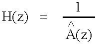 |
The speech synthesis filter with quantized coefficients |
| ai | The unquantized linear prediction parameters (direct form |
| coefficients) | |
| âi | The quantized linear prediction parameters |
 |
The long term synthesis filter |
| W(z) | The perceptual weighting filter (unquantized coefficients) |
| γ1, γ2 | The perceptual weighting factors |
| FE(z) | Adaptive pre-filter |
| T | The nearest integer pitch lag to the closed-loop fractional pitch lag |
| of the subframe | |
| β | The adaptive pre-filter coefficient (the quantized pitch gain) |
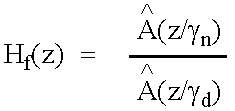 |
The formant postfilter |
| γn | Control coefficient for the amount of the formant post-filtering |
| γd | Control coefficient for the amount of the formant post-filtering |
| Ht(z) | Tilt compensation filter |
| γt | Control coefficient for the amount of the tile compensation filtering |
| μ= γtk′1 | A tilt factor, with k′1 being the first reflection coefficient |
| hf(n) | The truncated impulse response of the formant postfilter |
| Lh | The length of hf(n) |
| rh(i) | The auto-correlations of hf(n) |
| Â(z/γn) | The inverse filter (numerator) part of the formant postfilter |
| 1/Â(z/γd) | The synthesis filter (denominator) part of the formant postfilter |
| {circumflex over (r)}(n) | The AGC-controlled gain scaling factor of the adaptive postfilter |
| ht(z) | Impulse response of the tilt compensation filter |
| βSC(n) | The AGC-controlled gain scaling factor of the adaptive postfilter |
| α | The AGC factor of the adaptive postfilter |
| H1(z) | Pre-processing high-pass filter |
| wI(n), wII(n) | LP analysis windows |
| L1 (I) | Length of the first part of the LP analysis window wI(n) |
| L2 (I) | Length of the second part of the LP analysis window wI(n) |
| L1 (II) | Length of the first part of the LP analysis window wII(n) |
| L2 (II) | Length of the second part of the LP analysis window wII(n) |
| rac(k) | The auto-correlations of the windowed speech s′(n) |
| wlag(i) | Lag window for the auto-correlations (60 Hz bandwidth |
| expansion) | |
| f0 | The bandwidth expansion in Hz |
| fs | The sampling frequency in Hz |
| r′ac(k) | The modified (bandwidth expanded) auto-correlations |
| ELD(i) | The prediction error in the ith iteration of the Levinson algorithm |
| ki | The ith reflection coefficient |
| aj (i) | The jth direct form coefficient in the ith iteration of the Levinson |
| algorithm | |
| F′1(z) | Symmetric LSF polynomial |
| F′2(z) | Antisymmetric LSF polynomial |
| F1(z) | Polynomial F′1(z) with root = −1 eliminated |
| F2(z) | Polynomial F′2(z) with root = 1 eliminated |
| qi | The line spectral pairs (LSPs) in the cosine domain |
| q | An LSF vector in the cosine domain |
| {circumflex over (q)}i (n) | The quantized LSF vector at the ith subframe of the frame n |
| ωi | The line spectral frequencies (LSFs) |
| Tm(x) | A mth order Chebyshev polynomial |
| f1(i), f2(i) | The coefficients of the polynomials F1(z) and F2(z) |
| f′1(i), f′2(i) | The coefficients of the polynomials F′1(z) and F′2(z) |
| f(i) | The coefficients of either F1(z) or F2(z) |
| c(x) | Sum polynomial of the Chebyshev polynomials |
| x | Cosine of angular frequency ω |
| λk | Recursion coefficients for the Chebyshev polynomial evaluation |
| fi | The line spectral frequencies (LSFs) in Hz |
| ft = [f1f2 . . . f10] | The vector representation of the LSFs in Hz |
| z(1)(n), z(2)(n) | The mean-removed LSF vectors at frame n |
| r(1)(n), r(2)(n) | The LSF prediction residual vectors at frame n |
| p(n) | The predicted LSF vector at frame n |
| {circumflex over (r)}(2)(n − 1) | The quantized second residual vector at the past frame |
| {circumflex over (f)}k | The quantized LSF vector at quantization index k |
| ELSP | The LSF quantization error |
| wi, i = 1, . . . 10, | LSF-quantization weighting factors |
| di | The distance between the line spectral frequencies fi+1 and Fi−1 |
| h(n) | The impulse response of the weighted synthesis filter |
| Ok | The correlation maxima at delays ti, i = 1, . . . 3 |
| (Mi, ti), i = 1, . . . , 3 | The normalized correlation maxima Mi and the corresponding |
| delays ti ,i = 1, . . ., 3 | |
 |
The weighted synthesis filter |
| A(z/γ1) | The numerator of the perceptual weighting filter |
| 1/A(z/γ2) | The denominator of the perceptual weighting filter |
| T1 | The nearest integer to the fractional pitch lag of the previous (1st |
| or 3rd) subframe | |
| s′(n) | The windowed speech signal |
| sw(n) | The weighted speech signal |
| ŝ(n) | Reconstructed speech signal |
| ŝ′(n) | The gain-scaled post-filtered signal |
| ŝf(n) | Post-filtered speech signal (before scaling) |
| x(n) | The target signal for adaptive codebook search |
| x2(n), x2 t | The target signal for Fixed codebook search |
| resLP(n) | The LP residual signal |
| c(n) | The fixed codebook vector |
| v(n) | The adaptive codebook vector |
| y(n) = v(n)*h(n) | The filtered adaptive codebook vector |
| The filtered fixed codebook vector | |
| yk(n) | The past filtered excitation |
| u(n) | The excitation signal |
| û′(n) | The gain-scaled emphasized excitation signal |
| Top | The best open-loop lag |
| tmin | Minimum lag search value |
| tmax | Maximum lag search value |
| R(k) | Correlation term to be maximized in the adaptive codebook search |
| R(k)t | The interpolated value of R(k) for the integer delay k and fraction |
| t | |
| Ak | Correlation term to be maximized in the algebraic codebook search |
| at index k | |
| Ck | The correlation in the numerator of Ak at index k |
| CDk | The energy in the denominator of Ak at index k |
| d = Htx2 | The correlation between the target signal x2(n) and the impulse |
| response h(n), i.e., backward filtered target | |
| H | The lower triangular Toepliz convolution matrix with diagonal |
| h(0) and lower diagonals h(1), . . . , h(39) | |
| Φ = HtH | The matrix of correlations of h(n) |
| d(n) | The elements of the vector d |
| φ(i, j) | The elements of the symmetric matrix Φ |
| ck | The innovation vector |
| C | The correlation in the numerator of Ak |
| mi | The position of the ith pulse |
| Υi | The amplitude of the ith pulse |
| Np | The number of pulses in the fixed codebook excitation |
| ED | The energy in the denominator of Ak |
| resLTP(n) | The normalized long-term prediction residual |
| b(n) | The sum of the normalized d(n) vector and normalized long-term |
| prediction residual resLTP(n) | |
| sb(n) | The sign signal for the algebraic codebook search |
| zt, z(n) | The fixed codebook vector convolved with h(n) |
| E(n) | The mean-removed innovation energy (in dB) |
| {overscore (E)} | The mean of the innovation energy |
| {tilde over (E)}(n) | The predicted energy |
| [b1 b2 b3 b4] | The MA prediction coefficients |
| {circumflex over (R)}(k) | The quantized prediction error at subframe k |
| El | The mean innovation energy |
| R(n) | The prediction error of the fixed-codebook gain quantization |
| EQ | The quantization error of the fixed-codebook gain quantization |
| e(n) | The states of the synthesis filter 1/Â(z) |
| ew(n) | The perceptually weighted error of the analysis-by-synthesis |
| search | |
| η | The gain scaling factor for the emphasized excitation |
| gc | The fixed-codebook gain |
| ĝc | The quantized fixed codebook gain |
| gp | The adaptive codebook gain |
| ĝp | The quantized adaptive codebook gain |
| γgc = gc/g′c | A correction factor between the gain gc and the estimated one gc |
| {circumflex over (γ)}gc | The optimum value for γgc |
| γsc | Gain scaling factor |
| AGC | Adaptive Gain Control |
| AMR | Adaptive Multi Rate |
| CELP | Code Excited Linear Prediction |
| C/I | Carrier-to-Interferer ratio |
| DTX | Discontinuous Transmission |
| EFR | Enhanced Full Rate |
| FIR | Finite Impulse Response |
| FR | Full Rate |
| HR | Half Rate |
| LP | Linear Prediction |
| LPC | Linear Predictive Coding |
| LSF | Line Spectral Frequency |
| LSF | Line Spectral Pair |
| LTP | Long Term Predictor (or Long Term Prediction) |
| MA | Moving Average |
| TFO | Tandem Free Operation |
| VAD | Voice Activity Detection |
Claims (25)
Priority Applications (3)
| Application Number | Priority Date | Filing Date | Title |
|---|---|---|---|
| US09/156,650 US6260010B1 (en) | 1998-08-24 | 1998-09-18 | Speech encoder using gain normalization that combines open and closed loop gains |
| TW088114351A TW454171B (en) | 1998-08-24 | 1999-08-21 | Speech encoder using gain normalization that combines open and closed loop gains |
| PCT/US1999/019136 WO2000011659A1 (en) | 1998-08-24 | 1999-08-24 | Speech encoder using gain normalization that combines open and closed loop gains |
Applications Claiming Priority (2)
| Application Number | Priority Date | Filing Date | Title |
|---|---|---|---|
| US9756998P | 1998-08-24 | 1998-08-24 | |
| US09/156,650 US6260010B1 (en) | 1998-08-24 | 1998-09-18 | Speech encoder using gain normalization that combines open and closed loop gains |
Publications (1)
| Publication Number | Publication Date |
|---|---|
| US6260010B1 true US6260010B1 (en) | 2001-07-10 |
Family
ID=26793425
Family Applications (1)
| Application Number | Title | Priority Date | Filing Date |
|---|---|---|---|
| US09/156,650 Expired - Lifetime US6260010B1 (en) | 1998-08-24 | 1998-09-18 | Speech encoder using gain normalization that combines open and closed loop gains |
Country Status (3)
| Country | Link |
|---|---|
| US (1) | US6260010B1 (en) |
| TW (1) | TW454171B (en) |
| WO (1) | WO2000011659A1 (en) |
Cited By (36)
| Publication number | Priority date | Publication date | Assignee | Title |
|---|---|---|---|---|
| US6385574B1 (en) * | 1999-11-08 | 2002-05-07 | Lucent Technologies, Inc. | Reusing invalid pulse positions in CELP vocoding |
| US6397176B1 (en) * | 1998-08-24 | 2002-05-28 | Conexant Systems, Inc. | Fixed codebook structure including sub-codebooks |
| US6418405B1 (en) * | 1999-09-30 | 2002-07-09 | Motorola, Inc. | Method and apparatus for dynamic segmentation of a low bit rate digital voice message |
| US6424942B1 (en) * | 1998-10-26 | 2002-07-23 | Telefonaktiebolaget Lm Ericsson (Publ) | Methods and arrangements in a telecommunications system |
| US6424938B1 (en) * | 1998-11-23 | 2002-07-23 | Telefonaktiebolaget L M Ericsson | Complex signal activity detection for improved speech/noise classification of an audio signal |
| US6523002B1 (en) * | 1999-09-30 | 2003-02-18 | Conexant Systems, Inc. | Speech coding having continuous long term preprocessing without any delay |
| US6539349B1 (en) * | 2000-02-15 | 2003-03-25 | Lucent Technologies Inc. | Constraining pulse positions in CELP vocoding |
| US20030061038A1 (en) * | 2001-09-07 | 2003-03-27 | Christof Faller | Distortion-based method and apparatus for buffer control in a communication system |
| US20030139923A1 (en) * | 2001-12-25 | 2003-07-24 | Jhing-Fa Wang | Method and apparatus for speech coding and decoding |
| US6732069B1 (en) * | 1998-09-16 | 2004-05-04 | Telefonaktiebolaget Lm Ericsson (Publ) | Linear predictive analysis-by-synthesis encoding method and encoder |
| US20040098255A1 (en) * | 2002-11-14 | 2004-05-20 | France Telecom | Generalized analysis-by-synthesis speech coding method, and coder implementing such method |
| US6778953B1 (en) * | 2000-06-02 | 2004-08-17 | Agere Systems Inc. | Method and apparatus for representing masked thresholds in a perceptual audio coder |
| US20040181411A1 (en) * | 2003-03-15 | 2004-09-16 | Mindspeed Technologies, Inc. | Voicing index controls for CELP speech coding |
| US20050195925A1 (en) * | 2003-11-21 | 2005-09-08 | Mario Traber | Process and device for the prediction of noise contained in a received signal |
| US20050251387A1 (en) * | 2003-05-01 | 2005-11-10 | Nokia Corporation | Method and device for gain quantization in variable bit rate wideband speech coding |
| US20050261897A1 (en) * | 2002-12-24 | 2005-11-24 | Nokia Corporation | Method and device for robust predictive vector quantization of linear prediction parameters in variable bit rate speech coding |
| US20060089833A1 (en) * | 1998-08-24 | 2006-04-27 | Conexant Systems, Inc. | Pitch determination based on weighting of pitch lag candidates |
| US7191123B1 (en) * | 1999-11-18 | 2007-03-13 | Voiceage Corporation | Gain-smoothing in wideband speech and audio signal decoder |
| US20070265842A1 (en) * | 2006-05-09 | 2007-11-15 | Nokia Corporation | Adaptive voice activity detection |
| US20080027718A1 (en) * | 2006-07-31 | 2008-01-31 | Venkatesh Krishnan | Systems, methods, and apparatus for gain factor limiting |
| US20080162121A1 (en) * | 2006-12-28 | 2008-07-03 | Samsung Electronics Co., Ltd | Method, medium, and apparatus to classify for audio signal, and method, medium and apparatus to encode and/or decode for audio signal using the same |
| WO2007111649A3 (en) * | 2006-03-20 | 2009-04-30 | Mindspeed Tech Inc | Open-loop pitch track smoothing |
| US20100057448A1 (en) * | 2006-11-29 | 2010-03-04 | Loquenda S.p.A. | Multicodebook source-dependent coding and decoding |
| US20100174542A1 (en) * | 2009-01-06 | 2010-07-08 | Skype Limited | Speech coding |
| US20100174532A1 (en) * | 2009-01-06 | 2010-07-08 | Koen Bernard Vos | Speech encoding |
| US20100174547A1 (en) * | 2009-01-06 | 2010-07-08 | Skype Limited | Speech coding |
| US20100174541A1 (en) * | 2009-01-06 | 2010-07-08 | Skype Limited | Quantization |
| US20100174537A1 (en) * | 2009-01-06 | 2010-07-08 | Skype Limited | Speech coding |
| US20100174534A1 (en) * | 2009-01-06 | 2010-07-08 | Koen Bernard Vos | Speech coding |
| US20100174538A1 (en) * | 2009-01-06 | 2010-07-08 | Koen Bernard Vos | Speech encoding |
| US20110077940A1 (en) * | 2009-09-29 | 2011-03-31 | Koen Bernard Vos | Speech encoding |
| US20110153335A1 (en) * | 2008-05-23 | 2011-06-23 | Hyen-O Oh | Method and apparatus for processing audio signals |
| US20110173005A1 (en) * | 2008-07-11 | 2011-07-14 | Johannes Hilpert | Efficient Use of Phase Information in Audio Encoding and Decoding |
| TWI581253B (en) * | 2014-03-19 | 2017-05-01 | 弗勞恩霍夫爾協會 | Apparatus and method for generating an error concealment signal using power compensation |
| US9852738B2 (en) * | 2014-06-25 | 2017-12-26 | Huawei Technologies Co.,Ltd. | Method and apparatus for processing lost frame |
| US10068578B2 (en) | 2013-07-16 | 2018-09-04 | Huawei Technologies Co., Ltd. | Recovering high frequency band signal of a lost frame in media bitstream according to gain gradient |
Families Citing this family (8)
| Publication number | Priority date | Publication date | Assignee | Title |
|---|---|---|---|---|
| CN100362568C (en) | 2000-04-24 | 2008-01-16 | 高通股份有限公司 | Method and apparatus for predictively quantizing voiced speech |
| US8027242B2 (en) | 2005-10-21 | 2011-09-27 | Qualcomm Incorporated | Signal coding and decoding based on spectral dynamics |
| US8392176B2 (en) | 2006-04-10 | 2013-03-05 | Qualcomm Incorporated | Processing of excitation in audio coding and decoding |
| WO2008108721A1 (en) * | 2007-03-05 | 2008-09-12 | Telefonaktiebolaget Lm Ericsson (Publ) | Method and arrangement for controlling smoothing of stationary background noise |
| US8428957B2 (en) | 2007-08-24 | 2013-04-23 | Qualcomm Incorporated | Spectral noise shaping in audio coding based on spectral dynamics in frequency sub-bands |
| MY164399A (en) * | 2009-10-20 | 2017-12-15 | Fraunhofer Ges Forschung | Multi-mode audio codec and celp coding adapted therefore |
| TWI479160B (en) * | 2010-12-20 | 2015-04-01 | Hon Hai Prec Ind Co Ltd | Test apparatus and method |
| CN108028048B (en) | 2015-06-30 | 2022-06-21 | 弗劳恩霍夫应用研究促进协会 | Method and apparatus for correlating noise and for analysis |
Citations (6)
| Publication number | Priority date | Publication date | Assignee | Title |
|---|---|---|---|---|
| EP0501420A2 (en) | 1991-02-26 | 1992-09-02 | Nec Corporation | Speech coding method and system |
| US5745871A (en) * | 1991-09-10 | 1998-04-28 | Lucent Technologies | Pitch period estimation for use with audio coders |
| US5751903A (en) * | 1994-12-19 | 1998-05-12 | Hughes Electronics | Low rate multi-mode CELP codec that encodes line SPECTRAL frequencies utilizing an offset |
| US5778338A (en) * | 1991-06-11 | 1998-07-07 | Qualcomm Incorporated | Variable rate vocoder |
| US5946651A (en) * | 1995-06-16 | 1999-08-31 | Nokia Mobile Phones | Speech synthesizer employing post-processing for enhancing the quality of the synthesized speech |
| US5956683A (en) * | 1993-12-22 | 1999-09-21 | Qualcomm Incorporated | Distributed voice recognition system |
-
1998
- 1998-09-18 US US09/156,650 patent/US6260010B1/en not_active Expired - Lifetime
-
1999
- 1999-08-21 TW TW088114351A patent/TW454171B/en not_active IP Right Cessation
- 1999-08-24 WO PCT/US1999/019136 patent/WO2000011659A1/en not_active Ceased
Patent Citations (6)
| Publication number | Priority date | Publication date | Assignee | Title |
|---|---|---|---|---|
| EP0501420A2 (en) | 1991-02-26 | 1992-09-02 | Nec Corporation | Speech coding method and system |
| US5778338A (en) * | 1991-06-11 | 1998-07-07 | Qualcomm Incorporated | Variable rate vocoder |
| US5745871A (en) * | 1991-09-10 | 1998-04-28 | Lucent Technologies | Pitch period estimation for use with audio coders |
| US5956683A (en) * | 1993-12-22 | 1999-09-21 | Qualcomm Incorporated | Distributed voice recognition system |
| US5751903A (en) * | 1994-12-19 | 1998-05-12 | Hughes Electronics | Low rate multi-mode CELP codec that encodes line SPECTRAL frequencies utilizing an offset |
| US5946651A (en) * | 1995-06-16 | 1999-08-31 | Nokia Mobile Phones | Speech synthesizer employing post-processing for enhancing the quality of the synthesized speech |
Non-Patent Citations (13)
| Title |
|---|
| "Digital Cellular Telecommunications System; Comfort Noise Aspects for Enhanced Full Rate (EFR) Speech Traffic Channels (GSM 06.62)," May 1996, pp. 1-16. |
| B.S. Atal, V. Cuperman, and A. Gersho (Editors), Advances in Speech Coding, Kluwer Academic Publishers; I. A. Gerson and M.A. Jasiuk (Authors), Chapter 7: "Vector Sum Excited Linear Prediction (VSELP)," 1991, pp. 69-79. |
| B.S. Atal, V. Cuperman, and A. Gersho (Editors), Advances in Speech Coding, Kluwer Academic Publishers; J.P. Campbell, Jr., T.E. Tremain, and V.C. Welch (Authors), Chapter 12: "The DOD 4.8 KBPS Standard (Proposed Federal Standard 1016)", 1991, pp. 121-133. |
| B.S. Atal, V. Cuperman, and A. Gersho (Editors), Advances in Speech Coding, Kluwer Academic Publishers; R.A. Salami (Author), Chapter 14: "Binary Pulse Excitation: A Novel Approach to Low Complexity CELP Coding," 1991, pp. 145-157. |
| B.S. Atal, V. Cuperman, and A. Gersho (Editors), Speech and Audio Coding for Wireless and Network Applications, Kluwer Academic Publishers; T. Taniguchi, Y. Tanaka and Y. Ohta (Authors), Chapter 27: "Structured Stochastic Codebook and Codebook Adaptation for CELP," 1993, pp. 217-224. |
| C. Laflamme, J-P. Adoul, H.Y. Su, and S. Morissette, "On Reducing Computational Complexity of Codebook Search in CELP Coder Through the Use of Algebraic Codes," 1990, pp. 177-180. |
| Chih-Chung Kuo, Fu-Rong Jean, and Hsiao-Chuan Wang, "Speech Classification Embedded in Adaptive Codebook Search for Low Bit-Rate CELP Coding," IEEE Transactions on Speechand Audio Processing, vol. 3, No. 1, Jan. 1995, pp. 1-5. |
| Erdal Paksoy, Alan McCree, and Vish Viswanathan, "A Variable-Rate Multimodal Speech Coder with Gain-Matched Analysis-By-Synthesis," 1997, pp. 751-754. |
| Gerhard Schroeder, "International Telecommunication Union Telecommunications Standardization Sector," Jun. 1995, pp. i-iv, 1-42. |
| Jae H. Chung and Ronald W. Schafer, "Gain Normalization in a 4200 BPS Homomorphic Vocoder", IEEE International Conference on Communications ICC '90 Including Supercomm Technical Sessions. Supercom ICC '90 Conference Record, vol. 3, 16-19, Apr. 1990, pp. 942-946. |
| W. B. Kleijn and K.K. Paliwal (Editors), Speech Coding and Synthesis, Elsevier Science B.V.; A. Das, E. Paskoy and A. Gersho (Authors), Chapter 7: "Multimode and Variable-Rate Coding of Speech," 1995, pp. 257-288. |
| W. B. Kleijn and K.K. Paliwal (Editors), Speech Coding and Synthesis, Elsevier Science B.V.; Kroon and W.B. Kleijn (Authors), Chapter 3: "Linear-Prediction Based on Analysis-by-Synthesis Coding", 1995, pp. 81-113. |
| W. Bastiaan Kleijn and Peter Kroon, "The RCELP Speech-Coding Algorithm," vol. 5, No. 5, Sep.-Oct. 1994, pp. 39/573-47/581. |
Cited By (87)
| Publication number | Priority date | Publication date | Assignee | Title |
|---|---|---|---|---|
| US6397176B1 (en) * | 1998-08-24 | 2002-05-28 | Conexant Systems, Inc. | Fixed codebook structure including sub-codebooks |
| US7266493B2 (en) | 1998-08-24 | 2007-09-04 | Mindspeed Technologies, Inc. | Pitch determination based on weighting of pitch lag candidates |
| US7072832B1 (en) * | 1998-08-24 | 2006-07-04 | Mindspeed Technologies, Inc. | System for speech encoding having an adaptive encoding arrangement |
| US20060089833A1 (en) * | 1998-08-24 | 2006-04-27 | Conexant Systems, Inc. | Pitch determination based on weighting of pitch lag candidates |
| US6732069B1 (en) * | 1998-09-16 | 2004-05-04 | Telefonaktiebolaget Lm Ericsson (Publ) | Linear predictive analysis-by-synthesis encoding method and encoder |
| US20070255561A1 (en) * | 1998-09-18 | 2007-11-01 | Conexant Systems, Inc. | System for speech encoding having an adaptive encoding arrangement |
| US9190066B2 (en) | 1998-09-18 | 2015-11-17 | Mindspeed Technologies, Inc. | Adaptive codebook gain control for speech coding |
| US20090024386A1 (en) * | 1998-09-18 | 2009-01-22 | Conexant Systems, Inc. | Multi-mode speech encoding system |
| US20080319740A1 (en) * | 1998-09-18 | 2008-12-25 | Mindspeed Technologies, Inc. | Adaptive gain reduction for encoding a speech signal |
| US20080294429A1 (en) * | 1998-09-18 | 2008-11-27 | Conexant Systems, Inc. | Adaptive tilt compensation for synthesized speech |
| US20080288246A1 (en) * | 1998-09-18 | 2008-11-20 | Conexant Systems, Inc. | Selection of preferential pitch value for speech processing |
| US20090182558A1 (en) * | 1998-09-18 | 2009-07-16 | Minspeed Technologies, Inc. (Newport Beach, Ca) | Selection of scalar quantixation (SQ) and vector quantization (VQ) for speech coding |
| US20080147384A1 (en) * | 1998-09-18 | 2008-06-19 | Conexant Systems, Inc. | Pitch determination for speech processing |
| US8620647B2 (en) | 1998-09-18 | 2013-12-31 | Wiav Solutions Llc | Selection of scalar quantixation (SQ) and vector quantization (VQ) for speech coding |
| US8635063B2 (en) | 1998-09-18 | 2014-01-21 | Wiav Solutions Llc | Codebook sharing for LSF quantization |
| US8650028B2 (en) | 1998-09-18 | 2014-02-11 | Mindspeed Technologies, Inc. | Multi-mode speech encoding system for encoding a speech signal used for selection of one of the speech encoding modes including multiple speech encoding rates |
| US9401156B2 (en) | 1998-09-18 | 2016-07-26 | Samsung Electronics Co., Ltd. | Adaptive tilt compensation for synthesized speech |
| US20090164210A1 (en) * | 1998-09-18 | 2009-06-25 | Minspeed Technologies, Inc. | Codebook sharing for LSF quantization |
| US9269365B2 (en) | 1998-09-18 | 2016-02-23 | Mindspeed Technologies, Inc. | Adaptive gain reduction for encoding a speech signal |
| US6424942B1 (en) * | 1998-10-26 | 2002-07-23 | Telefonaktiebolaget Lm Ericsson (Publ) | Methods and arrangements in a telecommunications system |
| US6424938B1 (en) * | 1998-11-23 | 2002-07-23 | Telefonaktiebolaget L M Ericsson | Complex signal activity detection for improved speech/noise classification of an audio signal |
| US6418405B1 (en) * | 1999-09-30 | 2002-07-09 | Motorola, Inc. | Method and apparatus for dynamic segmentation of a low bit rate digital voice message |
| US6523002B1 (en) * | 1999-09-30 | 2003-02-18 | Conexant Systems, Inc. | Speech coding having continuous long term preprocessing without any delay |
| US6385574B1 (en) * | 1999-11-08 | 2002-05-07 | Lucent Technologies, Inc. | Reusing invalid pulse positions in CELP vocoding |
| US7191123B1 (en) * | 1999-11-18 | 2007-03-13 | Voiceage Corporation | Gain-smoothing in wideband speech and audio signal decoder |
| US6539349B1 (en) * | 2000-02-15 | 2003-03-25 | Lucent Technologies Inc. | Constraining pulse positions in CELP vocoding |
| US6778953B1 (en) * | 2000-06-02 | 2004-08-17 | Agere Systems Inc. | Method and apparatus for representing masked thresholds in a perceptual audio coder |
| US7062429B2 (en) * | 2001-09-07 | 2006-06-13 | Agere Systems Inc. | Distortion-based method and apparatus for buffer control in a communication system |
| US20060184358A1 (en) * | 2001-09-07 | 2006-08-17 | Agere Systems Guardian Corp. | Distortion-based method and apparatus for buffer control in a communication system |
| US8442819B2 (en) | 2001-09-07 | 2013-05-14 | Agere Systems Llc | Distortion-based method and apparatus for buffer control in a communication system |
| US20030061038A1 (en) * | 2001-09-07 | 2003-03-27 | Christof Faller | Distortion-based method and apparatus for buffer control in a communication system |
| US7305337B2 (en) * | 2001-12-25 | 2007-12-04 | National Cheng Kung University | Method and apparatus for speech coding and decoding |
| US20030139923A1 (en) * | 2001-12-25 | 2003-07-24 | Jhing-Fa Wang | Method and apparatus for speech coding and decoding |
| US20040098255A1 (en) * | 2002-11-14 | 2004-05-20 | France Telecom | Generalized analysis-by-synthesis speech coding method, and coder implementing such method |
| US20050261897A1 (en) * | 2002-12-24 | 2005-11-24 | Nokia Corporation | Method and device for robust predictive vector quantization of linear prediction parameters in variable bit rate speech coding |
| US20070112564A1 (en) * | 2002-12-24 | 2007-05-17 | Milan Jelinek | Method and device for robust predictive vector quantization of linear prediction parameters in variable bit rate speech coding |
| US7502734B2 (en) | 2002-12-24 | 2009-03-10 | Nokia Corporation | Method and device for robust predictive vector quantization of linear prediction parameters in sound signal coding |
| US7149683B2 (en) * | 2002-12-24 | 2006-12-12 | Nokia Corporation | Method and device for robust predictive vector quantization of linear prediction parameters in variable bit rate speech coding |
| US20040181411A1 (en) * | 2003-03-15 | 2004-09-16 | Mindspeed Technologies, Inc. | Voicing index controls for CELP speech coding |
| US7778827B2 (en) * | 2003-05-01 | 2010-08-17 | Nokia Corporation | Method and device for gain quantization in variable bit rate wideband speech coding |
| US20050251387A1 (en) * | 2003-05-01 | 2005-11-10 | Nokia Corporation | Method and device for gain quantization in variable bit rate wideband speech coding |
| US7616714B2 (en) * | 2003-11-21 | 2009-11-10 | Infineon Technologies Ag | Process and device for the prediction of noise contained in a received signal |
| US20050195925A1 (en) * | 2003-11-21 | 2005-09-08 | Mario Traber | Process and device for the prediction of noise contained in a received signal |
| CN101506873B (en) * | 2006-03-20 | 2012-08-15 | 曼德斯必德技术公司 | Open loop pitch tracking smoothing |
| US8386245B2 (en) | 2006-03-20 | 2013-02-26 | Mindspeed Technologies, Inc. | Open-loop pitch track smoothing |
| WO2007111649A3 (en) * | 2006-03-20 | 2009-04-30 | Mindspeed Tech Inc | Open-loop pitch track smoothing |
| US20100241424A1 (en) * | 2006-03-20 | 2010-09-23 | Mindspeed Technologies, Inc. | Open-Loop Pitch Track Smoothing |
| EP2228789A1 (en) * | 2006-03-20 | 2010-09-15 | Mindspeed Technologies, Inc. | Open-loop pitch track smoothing |
| US8032370B2 (en) * | 2006-05-09 | 2011-10-04 | Nokia Corporation | Method, apparatus, system and software product for adaptation of voice activity detection parameters based on the quality of the coding modes |
| US20070265842A1 (en) * | 2006-05-09 | 2007-11-15 | Nokia Corporation | Adaptive voice activity detection |
| US8645133B2 (en) | 2006-05-09 | 2014-02-04 | Core Wireless Licensing S.A.R.L. | Adaptation of voice activity detection parameters based on encoding modes |
| US20080027718A1 (en) * | 2006-07-31 | 2008-01-31 | Venkatesh Krishnan | Systems, methods, and apparatus for gain factor limiting |
| US9454974B2 (en) * | 2006-07-31 | 2016-09-27 | Qualcomm Incorporated | Systems, methods, and apparatus for gain factor limiting |
| US8447594B2 (en) * | 2006-11-29 | 2013-05-21 | Loquendo S.P.A. | Multicodebook source-dependent coding and decoding |
| US20100057448A1 (en) * | 2006-11-29 | 2010-03-04 | Loquenda S.p.A. | Multicodebook source-dependent coding and decoding |
| US20080162121A1 (en) * | 2006-12-28 | 2008-07-03 | Samsung Electronics Co., Ltd | Method, medium, and apparatus to classify for audio signal, and method, medium and apparatus to encode and/or decode for audio signal using the same |
| US20110153335A1 (en) * | 2008-05-23 | 2011-06-23 | Hyen-O Oh | Method and apparatus for processing audio signals |
| US9070364B2 (en) * | 2008-05-23 | 2015-06-30 | Lg Electronics Inc. | Method and apparatus for processing audio signals |
| TWI449031B (en) * | 2008-07-11 | 2014-08-11 | Fraunhofer Ges Forschung | Audio encoder and method for generating encoded representation of audio signal, audio decoder and method for generating audio channel, and the related computer program product |
| US20110173005A1 (en) * | 2008-07-11 | 2011-07-14 | Johannes Hilpert | Efficient Use of Phase Information in Audio Encoding and Decoding |
| US8255228B2 (en) * | 2008-07-11 | 2012-08-28 | Fraunhofer-Gesellschaft Zur Foerderung Der Angewandten Forschung E.V. | Efficient use of phase information in audio encoding and decoding |
| US20100174547A1 (en) * | 2009-01-06 | 2010-07-08 | Skype Limited | Speech coding |
| US8670981B2 (en) * | 2009-01-06 | 2014-03-11 | Skype | Speech encoding and decoding utilizing line spectral frequency interpolation |
| US8463604B2 (en) | 2009-01-06 | 2013-06-11 | Skype | Speech encoding utilizing independent manipulation of signal and noise spectrum |
| US8433563B2 (en) | 2009-01-06 | 2013-04-30 | Skype | Predictive speech signal coding |
| US8396706B2 (en) | 2009-01-06 | 2013-03-12 | Skype | Speech coding |
| US8639504B2 (en) | 2009-01-06 | 2014-01-28 | Skype | Speech encoding utilizing independent manipulation of signal and noise spectrum |
| US8392178B2 (en) | 2009-01-06 | 2013-03-05 | Skype | Pitch lag vectors for speech encoding |
| US10026411B2 (en) | 2009-01-06 | 2018-07-17 | Skype | Speech encoding utilizing independent manipulation of signal and noise spectrum |
| US8655653B2 (en) | 2009-01-06 | 2014-02-18 | Skype | Speech coding by quantizing with random-noise signal |
| US9530423B2 (en) | 2009-01-06 | 2016-12-27 | Skype | Speech encoding by determining a quantization gain based on inverse of a pitch correlation |
| US20100174538A1 (en) * | 2009-01-06 | 2010-07-08 | Koen Bernard Vos | Speech encoding |
| US8849658B2 (en) | 2009-01-06 | 2014-09-30 | Skype | Speech encoding utilizing independent manipulation of signal and noise spectrum |
| US20100174534A1 (en) * | 2009-01-06 | 2010-07-08 | Koen Bernard Vos | Speech coding |
| US20100174537A1 (en) * | 2009-01-06 | 2010-07-08 | Skype Limited | Speech coding |
| US9263051B2 (en) | 2009-01-06 | 2016-02-16 | Skype | Speech coding by quantizing with random-noise signal |
| US20100174541A1 (en) * | 2009-01-06 | 2010-07-08 | Skype Limited | Quantization |
| US20100174532A1 (en) * | 2009-01-06 | 2010-07-08 | Koen Bernard Vos | Speech encoding |
| US20100174542A1 (en) * | 2009-01-06 | 2010-07-08 | Skype Limited | Speech coding |
| US20110077940A1 (en) * | 2009-09-29 | 2011-03-31 | Koen Bernard Vos | Speech encoding |
| US8452606B2 (en) | 2009-09-29 | 2013-05-28 | Skype | Speech encoding using multiple bit rates |
| US10068578B2 (en) | 2013-07-16 | 2018-09-04 | Huawei Technologies Co., Ltd. | Recovering high frequency band signal of a lost frame in media bitstream according to gain gradient |
| US10614817B2 (en) | 2013-07-16 | 2020-04-07 | Huawei Technologies Co., Ltd. | Recovering high frequency band signal of a lost frame in media bitstream according to gain gradient |
| TWI581253B (en) * | 2014-03-19 | 2017-05-01 | 弗勞恩霍夫爾協會 | Apparatus and method for generating an error concealment signal using power compensation |
| US9852738B2 (en) * | 2014-06-25 | 2017-12-26 | Huawei Technologies Co.,Ltd. | Method and apparatus for processing lost frame |
| US10311885B2 (en) | 2014-06-25 | 2019-06-04 | Huawei Technologies Co., Ltd. | Method and apparatus for recovering lost frames |
| US10529351B2 (en) | 2014-06-25 | 2020-01-07 | Huawei Technologies Co., Ltd. | Method and apparatus for recovering lost frames |
Also Published As
| Publication number | Publication date |
|---|---|
| TW454171B (en) | 2001-09-11 |
| WO2000011659A9 (en) | 2000-08-17 |
| WO2000011659A1 (en) | 2000-03-02 |
Similar Documents
| Publication | Publication Date | Title |
|---|---|---|
| US6260010B1 (en) | Speech encoder using gain normalization that combines open and closed loop gains | |
| US6493665B1 (en) | Speech classification and parameter weighting used in codebook search | |
| US6330533B2 (en) | Speech encoder adaptively applying pitch preprocessing with warping of target signal | |
| US6507814B1 (en) | Pitch determination using speech classification and prior pitch estimation | |
| US6480822B2 (en) | Low complexity random codebook structure | |
| US6173257B1 (en) | Completed fixed codebook for speech encoder | |
| US6823303B1 (en) | Speech encoder using voice activity detection in coding noise | |
| US6188980B1 (en) | Synchronized encoder-decoder frame concealment using speech coding parameters including line spectral frequencies and filter coefficients | |
| US6385573B1 (en) | Adaptive tilt compensation for synthesized speech residual | |
| US6449590B1 (en) | Speech encoder using warping in long term preprocessing | |
| US6240386B1 (en) | Speech codec employing noise classification for noise compensation | |
| EP1930881A2 (en) | Speech decoder employing noise compensation | |
| HK1038422B (en) | Speech encoder and method of searching a codebook | |
| HK1034347B (en) | Speech encoder and method for a speech encoder | |
| HK1151122A (en) | Speech encoding method and system | |
| HK1133734A (en) | Codebook sharing for lsf quantization | |
| HK1133735A (en) | Adaptive codebook gain control for speech coding | |
| HK1113431A (en) | Speech decoder employing noise compensation | |
| HK1133733A (en) | Gain smoothing for speech coding | |
| HK1133732A (en) | Open-loop pitch processing for speech coding | |
| HK1133731A (en) | Selection of scalar quantization(sq) and vector quantization (vq) for speech coding |
Legal Events
| Date | Code | Title | Description |
|---|---|---|---|
| AS | Assignment |
Owner name: ROCKWELL SEMICONDUCTOR SYSTEMS, INC., CALIFORNIA Free format text: ASSIGNMENT OF ASSIGNORS INTEREST;ASSIGNORS:GAO, YANG;THYSSEN, JES;BENYASSINE, ADIL;REEL/FRAME:009587/0484 Effective date: 19981103 |
|
| AS | Assignment |
Owner name: CONEXANT SYSTEMS, INC., CALIFORNIA Free format text: CHANGE OF NAME;ASSIGNORS:ROCKWELL SEMICONDUCTOR SYSTEMS, INC.;CONEXANT SYSTEMS, INC.;REEL/FRAME:010401/0020 Effective date: 19981202 |
|
| STCF | Information on status: patent grant |
Free format text: PATENTED CASE |
|
| FEPP | Fee payment procedure |
Free format text: PAYOR NUMBER ASSIGNED (ORIGINAL EVENT CODE: ASPN); ENTITY STATUS OF PATENT OWNER: LARGE ENTITY |
|
| AS | Assignment |
Owner name: MINDSPEED TECHNOLOGIES, CALIFORNIA Free format text: ASSIGNMENT OF ASSIGNORS INTEREST;ASSIGNOR:CONEXANT SYSTEMS, INC.;REEL/FRAME:014468/0137 Effective date: 20030627 |
|
| AS | Assignment |
Owner name: CONEXANT SYSTEMS, INC., CALIFORNIA Free format text: SECURITY AGREEMENT;ASSIGNOR:MINDSPEED TECHNOLOGIES, INC.;REEL/FRAME:014546/0305 Effective date: 20030930 |
|
| FPAY | Fee payment |
Year of fee payment: 4 |
|
| AS | Assignment |
Owner name: SKYWORKS SOLUTIONS, INC., MASSACHUSETTS Free format text: EXCLUSIVE LICENSE;ASSIGNOR:CONEXANT SYSTEMS, INC.;REEL/FRAME:019649/0544 Effective date: 20030108 Owner name: SKYWORKS SOLUTIONS, INC.,MASSACHUSETTS Free format text: EXCLUSIVE LICENSE;ASSIGNOR:CONEXANT SYSTEMS, INC.;REEL/FRAME:019649/0544 Effective date: 20030108 |
|
| AS | Assignment |
Owner name: WIAV SOLUTIONS LLC, VIRGINIA Free format text: ASSIGNMENT OF ASSIGNORS INTEREST;ASSIGNOR:SKYWORKS SOLUTIONS INC.;REEL/FRAME:019899/0305 Effective date: 20070926 |
|
| FPAY | Fee payment |
Year of fee payment: 8 |
|
| AS | Assignment |
Owner name: MINDSPEED TECHNOLOGIES, INC., CALIFORNIA Free format text: ASSIGNMENT OF ASSIGNORS INTEREST;ASSIGNOR:WIAV SOLUTIONS LLC;REEL/FRAME:025599/0487 Effective date: 20100928 |
|
| FPAY | Fee payment |
Year of fee payment: 12 |
|
| AS | Assignment |
Owner name: MINDSPEED TECHNOLOGIES, INC, CALIFORNIA Free format text: RELEASE OF SECURITY INTEREST;ASSIGNOR:CONEXANT SYSTEMS, INC;REEL/FRAME:031494/0937 Effective date: 20041208 |
|
| AS | Assignment |
Owner name: JPMORGAN CHASE BANK, N.A., AS ADMINISTRATIVE AGENT Free format text: SECURITY INTEREST;ASSIGNOR:MINDSPEED TECHNOLOGIES, INC.;REEL/FRAME:032495/0177 Effective date: 20140318 |
|
| AS | Assignment |
Owner name: GOLDMAN SACHS BANK USA, NEW YORK Free format text: SECURITY INTEREST;ASSIGNORS:M/A-COM TECHNOLOGY SOLUTIONS HOLDINGS, INC.;MINDSPEED TECHNOLOGIES, INC.;BROOKTREE CORPORATION;REEL/FRAME:032859/0374 Effective date: 20140508 Owner name: MINDSPEED TECHNOLOGIES, INC., CALIFORNIA Free format text: RELEASE BY SECURED PARTY;ASSIGNOR:JPMORGAN CHASE BANK, N.A.;REEL/FRAME:032861/0617 Effective date: 20140508 |
|
| AS | Assignment |
Owner name: MINDSPEED TECHNOLOGIES, LLC, MASSACHUSETTS Free format text: CHANGE OF NAME;ASSIGNOR:MINDSPEED TECHNOLOGIES, INC.;REEL/FRAME:039645/0264 Effective date: 20160725 |
|
| AS | Assignment |
Owner name: MACOM TECHNOLOGY SOLUTIONS HOLDINGS, INC., MASSACH Free format text: ASSIGNMENT OF ASSIGNORS INTEREST;ASSIGNOR:MINDSPEED TECHNOLOGIES, LLC;REEL/FRAME:044791/0600 Effective date: 20171017 |