US5960386A - Method for adaptively controlling the pitch gain of a vocoder's adaptive codebook - Google Patents
Method for adaptively controlling the pitch gain of a vocoder's adaptive codebook Download PDFInfo
- Publication number
- US5960386A US5960386A US08/649,554 US64955496A US5960386A US 5960386 A US5960386 A US 5960386A US 64955496 A US64955496 A US 64955496A US 5960386 A US5960386 A US 5960386A
- Authority
- US
- United States
- Prior art keywords
- pitch gain
- speech signal
- adaptive
- control unit
- receiving
- Prior art date
- Legal status (The legal status is an assumption and is not a legal conclusion. Google has not performed a legal analysis and makes no representation as to the accuracy of the status listed.)
- Expired - Lifetime
Links
Images


Classifications
-
- G—PHYSICS
- G10—MUSICAL INSTRUMENTS; ACOUSTICS
- G10L—SPEECH ANALYSIS OR SYNTHESIS; SPEECH RECOGNITION; SPEECH OR VOICE PROCESSING; SPEECH OR AUDIO CODING OR DECODING
- G10L19/00—Speech or audio signals analysis-synthesis techniques for redundancy reduction, e.g. in vocoders; Coding or decoding of speech or audio signals, using source filter models or psychoacoustic analysis
- G10L19/04—Speech or audio signals analysis-synthesis techniques for redundancy reduction, e.g. in vocoders; Coding or decoding of speech or audio signals, using source filter models or psychoacoustic analysis using predictive techniques
- G10L19/08—Determination or coding of the excitation function; Determination or coding of the long-term prediction parameters
-
- G—PHYSICS
- G10—MUSICAL INSTRUMENTS; ACOUSTICS
- G10L—SPEECH ANALYSIS OR SYNTHESIS; SPEECH RECOGNITION; SPEECH OR VOICE PROCESSING; SPEECH OR AUDIO CODING OR DECODING
- G10L19/00—Speech or audio signals analysis-synthesis techniques for redundancy reduction, e.g. in vocoders; Coding or decoding of speech or audio signals, using source filter models or psychoacoustic analysis
- G10L2019/0001—Codebooks
- G10L2019/0011—Long term prediction filters, i.e. pitch estimation
-
- H—ELECTRICITY
- H04—ELECTRIC COMMUNICATION TECHNIQUE
- H04N—PICTORIAL COMMUNICATION, e.g. TELEVISION
- H04N7/00—Television systems
- H04N7/14—Systems for two-way working
- H04N7/141—Systems for two-way working between two video terminals, e.g. videophone
- H04N7/142—Constructional details of the terminal equipment, e.g. arrangements of the camera and the display
- H04N2007/145—Handheld terminals
Definitions
- the present invention relates to communications; more specifically, voice encoding.
- a voice encoder is used to encode voice signals so as to minimize the amount of bandwidth that is used for transmitting over communication channels. It is important to minimize the amount of bandwidth used per communication channel so as to maximize the number of channels available within a given range of spectrum.
- vocoders using an adaptive codebook structure such as those in the class of code excited linear predictive (CELP) vocoders, encounter an instability problem when receiving periodic, sinusoidal or tonal inputs coupled with a communications channel error. Since all communication channels experience errors, this type of problem manifests itself relatively frequently for the above inputs. For example, when a DTMF (Dual Tone Multifrelquency) signal is received with errors, many vocoders become unstable and produce an output that exhibits amplitude oscillation.
- DTMF Dual Tone Multifrelquency
- An embodiment of the present invention solves the aforementioned problem by monitoring a gain used in the adaptive codebook portion of the encoder of a vocoder. This gain is monitored to determine when an instability condition is about to occur. When this condition is detected, the gain is controlled using adaptive parameters so that instability is avoided.
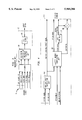
- FIG. 1 is a block diagram of a typical vocoder
- FIG. 2 illustrates the major functions of encoder 14 of vocoder 10
- FIG. 3 is a functional block diagram of decoder 20 of vocoder 10;
- FIG. 4 is a functional block diagram of an adaptive codebook unit
- FIG. 5 illustrates the steps executed by gain control unit 170.
- FIG. 1 illustrates a block diagram of a typical vocoder.
- Vocoder 10 receives digitized speech on input 12.
- the digitized speech is an analog speech signal that has been passed through an analog to digitized converter, and has been broken into frames where each frame is typically on the order of 20 milliseconds.
- the signal at input 12 is passed to encoder section 14 which encodes the speech so as decrease the amount of bandwidth used to transmit the speech.
- the encoded speech is made available at output 16.
- the encoded speech is received by the decode section of a similar vocoder at the other end of a communication channel.
- the decoder at the other end of the communication channel is similar or identical to the decoder portion of vocoder 10.
- Encoded speech is received by vocoder 10 through input 18, and is passed to decoder section 20.
- Decoder section 20 uses the encoded signals received from the transmitting vocoder to produce digitized speech at output 22.
- Vocoders are well known in the communications arts. For example, vocoders are described in "Speech and audio coding for wireless and network applications," edited by Bishnu S. Atal, Vladimir Cuperman, and Allen Gersho, 1993, by Kluwer Academic Publishers. Vocoders are widely available and manufactured by companies such as Qualcomm Incorporated of San Diego, Calif., and Lucent Technologies Inc., of Murray Hill, N.J.
- FIG. 2 illustrates the major functions of encoder 14 of vocoder 10.
- a digitized speech signal is received at input 12, and is passed to Linear predictive coder 40.
- Linear predictive coder 40 performs a linear predictive, analysis of the incoming speech once per frame. Linear predictive analysis is well known in the art and produces a linear predictive synthesis model of the vocal tract based on the input speech signal. The linear predictive parameters or coefficients describing this model are transmitted as part of the encoded speech signal through output 16.
- Coder 40 uses this model to produce a residual speech signal which represents the excitation that the model uses to reproduce the input speech signal.
- the residual speech signal is made available at output 42.
- the residual speech from output 42 is provided to input 48 of open-loop pitch search unit 50 to an input of adaptive codebook unit 72 and to fixed codebook unit 82.
- Impulse response unit 60 receives the linear predictive parameters from coder 40 and generates the impulse response of the model generated in coder 40. This impulse response is used in the adaptive and fixed codebook units.
- Open loop pitch search unit 50 uses the residual speech signal from coder 40 to model its pitch and provides a pitch, or what is commonly called the pitch period or pitch delay signal, at output 52.
- the pitch delay signal from output 52 and the impulse response signal from output 64 of impulse response unit 60 are received by input 70 of adaptive codebook unit 72.
- Adaptive codebook unit 72 produces a pitch gain output and a pitch index output which become part of encoded speech output 16 of vocoder 10.
- Output 74 of adaptive codebook unit 72 also provides the pitch gain and pitch index signals to input 80 of fixed codebook unit 82. Additionally, adaptive codebook unit 72 provides an excitation signal and an adaptive codebook target signal to input 80.
- the adaptive codebook unit 72 produces its outputs using, the digitized speech signal from input 12 and the residual speech signal produced by linear predictive coder 40.
- Adaptive codebook unit 72 uses the digitized speech signal and linear predictive coder 40's residual speech signal to form an adaptive codebook target signal.
- the adaptive codebook target signal is used as an input to fixed codebook unit 82, and as an input to a computation that produces the pitch gain, pitch index and excitation outputs of adaptive codebook unit 72.
- the adaptive codebook target signal, the pitch delay signal from open loop pitch search unit 50, and the impulse response from impulse response unit 60 are used to produced the pitch index, the pitch gain and excitation signals which are passed to fixed codebook unit 82.
- the manner in which these signals are computed is well known in the vocoder art.
- Fixed codebook unit 82 uses the inputs received from input 80 to produce a fixed gain output and a fixed index output which are used as part of the encoded speech at output 16.
- the fixed codebook unit attempts to model the stocastic part of the linear predictive coder 40's residual speech signal.
- a target for the fixed codebook search is produced by determining the error between the current adaptive codebook target signal and the residual speech signal.
- the fixed codebook search produces the fixed gain and fixed index signal for excitation pulses so as to minimize this error.
- the manner in which the fixed gain and fixed index signals are computed using the outputs from adaptive codebook unit 72 are well known in the vocoder art.
- FIG. 3 illustrates a functional block diagram of decoder 20 of vocoder 10.
- Encoded speech signals are received at input 18 of decoder 20.
- the encoded speech signals are received by decoder 100.
- Decoder 100 produces fixed and adaptive code vectors corresponding to the fixed index and pitch index signals, respectively. These code vectors are passed to the excitation construction portion of unit 110 along with the pitch gain and the fixed gain signals.
- the pitch gain signal is used to scale the adaptive vector which was produced using the pitch index signal
- the fixed gain signal is used to scale the fixed vector which was obtained using the fixed index signal.
- Decoder 100 passes the linear predictive code parameters to the filter or model synthesis section of unit 110.
- Unit 110 then uses the scaled vectors to excite the filter that is synthesized using the linear predictive coefficients produced by linear predictive coder 40, and produces an output signal which is representative of the digitized speech originally received at input 12.
- post filter 120 may be used to shape the spectrum of the digitized speech signal that is produced at output 20.
- the functional block diagrams can be implemented in various forms. Each block can be implemented individually using microprocessors or microcomputers, or they can be implemented using a single microprocessor or microcomputer. It is also possible to implement each or all of the functional blocks using programmable digital signal processing devices or specialized devices received from the aforementioned manufacturers or other semiconductor manufacturers.
- FIG. 4 illustrates a functional block diagram of adaptive codebook unit 140 that comprises an embodiment of the present invention.
- Adaptive codebook unit 140 would be used in place of adaptive code book unit 72 of FIG. 2.
- the adaptive codebook receives the digitized speech signal, linear predictive coder 40's residual speech signal, the pitch delay signal, and the output of impulse response unit 60.
- Adaptive codebook unit 140 includes adaptive target computational unit 150.
- Unit 150 uses the digitized speech signal and the residual signal From linear predictive coder 40 to produce the adaptive codebook target signal which is passed to fixed codebook unit 82.
- the adaptive codebook target signal, the pitch delay signal 50 and the impulse response signal of open-100p pitch search unit are used by adaptive codebook computational unit 158 to produce a pitch index signal, a pitch gain signal, and an excitation signal which are eventually passed to fixed codebook unit 82.
- the aforedescribed instabilities are corrected using gain control unit 170.
- Gain control unit 170 monitors the value of the pitch gain signal from unit 158 and produces a new pitch gain signal when necessary to avoid the aforementioned instability problems.
- the pitch gain signal from unit 170 is used in scaler 166 to scale the excitation signal before passing it to the fixed codebook unit 82.
- FIG. 5 illustrates steps executed by gain control unit 170.
- step 200 the pitch gain signal, g p is received by gain control unit 170.
- step 204 the gain signal g p is compared with a threshold signal g n-1 .
- the signal g n-1 is initialized at 0. If the gain g p is greater than the threshold signal g n-1 , step 208 is executed, and if the signal is not greater, step 212 is executed.
- Step 208 sets averaging constant ⁇ equal to ⁇ rise and then calculation step 214 is executed to calculate the updated threshold value g n .
- a typical value for ⁇ rise is 0.04.
- step 212 is executed.
- the received signal g p is compared to the value 1. If it is greater than 1, step 216 is executed, and if it is not greater than 1, step 218 is executed.
- Step 216 sets averaging constant ⁇ equal to A fall , and in step 218 averaging constant ⁇ is set equal to 1-g p /2.
- a typical value for A fall is 0.02
- step 214 is executed.
- the new threshold value g n is calculated.
- the value g n is formed using what is essentially an exponential time averaging function.
- the value g n is equal to ⁇ g p +(1- ⁇ )g n-1 .
- step 224 is executed.
- step 224 the pitch gain signal g p is compared with 1. If it is greater than 1, step 226 is executed, and if it is less than 1, step 230 is executed.
- new threshold value g n is compared with a fixed threshold T g . A typical value for T g is 1.0. If value g n is greater than the threshold value T g , step 234 is executed, and if it is not greater than the threshold value T g , step 230 is executed.
- the control gain value g n * is provided at the output of gain control unit 170. The initial value of g n * is typically set equal to 0.95.
- step 236 the value of g n * is updated by setting g n+1 * equal to ⁇ ctrl G low +(1- ⁇ ctrl )g n *. It is preferable to set the value ⁇ ctrl to 0.5, and the value G low to 0.9.
- step 230 is executed after either steps 224 or 226.
- g n+1 * is set equal to G ctrl
- step 240 the value of g p is provided at the output of gain control unit 170.
- a preferable value for G ctrl is 0.95.
- steps 204 through 214 are used to calculate the new value of g.
- step 214 it is determined whether the pitch gain, g p , received from codebook computation unit 158 should be modified by gain control unit 170.
- steps 224 and 226 the present pitch gain value, g p , and the averaged pitch gain value, g n , are examined to determine if an instability is likely. If it is determined that an instability is likely, the output of gain control unit 170 is set to an adaptive gain control value g n *. This output is used in place of the pitch gain g p received from codebook computation unit 158.
- step 236 the adaptive gain control g n * is updated.
- the pitch gain received from codebook computation unit 158 is passed unmodified to the output by gain control unit 170.
- the updated adaptive gain control g n+1 * is set equal to a fixed value G ctrl .
- the computation or process illustrated by FIG. 5 can be carried out on a frame-by-frame basis or on a more frequent basis depending on the vocoder being used.
Abstract
Description
Claims (15)
Priority Applications (1)
| Application Number | Priority Date | Filing Date | Title |
|---|---|---|---|
| US08/649,554 US5960386A (en) | 1996-05-17 | 1996-05-17 | Method for adaptively controlling the pitch gain of a vocoder's adaptive codebook |
Applications Claiming Priority (1)
| Application Number | Priority Date | Filing Date | Title |
|---|---|---|---|
| US08/649,554 US5960386A (en) | 1996-05-17 | 1996-05-17 | Method for adaptively controlling the pitch gain of a vocoder's adaptive codebook |
Related Child Applications (1)
| Application Number | Title | Priority Date | Filing Date |
|---|---|---|---|
| US09/258,824 Continuation-In-Part US6751473B1 (en) | 1998-03-31 | 1999-02-26 | Wireless communication terminal having a video image capability |
Publications (1)
| Publication Number | Publication Date |
|---|---|
| US5960386A true US5960386A (en) | 1999-09-28 |
Family
ID=24605307
Family Applications (1)
| Application Number | Title | Priority Date | Filing Date |
|---|---|---|---|
| US08/649,554 Expired - Lifetime US5960386A (en) | 1996-05-17 | 1996-05-17 | Method for adaptively controlling the pitch gain of a vocoder's adaptive codebook |
Country Status (1)
| Country | Link |
|---|---|
| US (1) | US5960386A (en) |
Cited By (12)
| Publication number | Priority date | Publication date | Assignee | Title |
|---|---|---|---|---|
| US6345255B1 (en) * | 1998-06-30 | 2002-02-05 | Nortel Networks Limited | Apparatus and method for coding speech signals by making use of an adaptive codebook |
| US6611800B1 (en) * | 1996-09-24 | 2003-08-26 | Sony Corporation | Vector quantization method and speech encoding method and apparatus |
| US20050219073A1 (en) * | 2002-05-22 | 2005-10-06 | Nec Corporation | Method and device for code conversion between audio encoding/decoding methods and storage medium thereof |
| US20060025990A1 (en) * | 2004-07-28 | 2006-02-02 | Boillot Marc A | Method and system for improving voice quality of a vocoder |
| US7191123B1 (en) * | 1999-11-18 | 2007-03-13 | Voiceage Corporation | Gain-smoothing in wideband speech and audio signal decoder |
| FR2897977A1 (en) * | 2006-02-28 | 2007-08-31 | France Telecom | Coded digital audio signal decoder`s e.g. G.729 decoder, adaptive excitation gain limiting method for e.g. voice over Internet protocol network, involves applying limitation to excitation gain if excitation gain is greater than given value |
| US20080086302A1 (en) * | 2006-10-06 | 2008-04-10 | Qualcomm Incorporated | Systems, methods, and apparatus for frame erasure recovery |
| US20090089050A1 (en) * | 2006-06-08 | 2009-04-02 | Huawei Technologies Co., Ltd. | Device and Method For Frame Lost Concealment |
| CN101286319B (en) * | 2006-12-26 | 2013-05-01 | 华为技术有限公司 | Speech coding system to improve packet loss repairing quality |
| CN104115220A (en) * | 2011-12-21 | 2014-10-22 | 华为技术有限公司 | Very short pitch detection and coding |
| US9336790B2 (en) | 2006-12-26 | 2016-05-10 | Huawei Technologies Co., Ltd | Packet loss concealment for speech coding |
| US10446173B2 (en) * | 2017-09-15 | 2019-10-15 | Fujitsu Limited | Apparatus, method for detecting speech production interval, and non-transitory computer-readable storage medium for storing speech production interval detection computer program |
Citations (12)
| Publication number | Priority date | Publication date | Assignee | Title |
|---|---|---|---|---|
| US4809334A (en) * | 1987-07-09 | 1989-02-28 | Communications Satellite Corporation | Method for detection and correction of errors in speech pitch period estimates |
| US5018200A (en) * | 1988-09-21 | 1991-05-21 | Nec Corporation | Communication system capable of improving a speech quality by classifying speech signals |
| US5127053A (en) * | 1990-12-24 | 1992-06-30 | General Electric Company | Low-complexity method for improving the performance of autocorrelation-based pitch detectors |
| US5142584A (en) * | 1989-07-20 | 1992-08-25 | Nec Corporation | Speech coding/decoding method having an excitation signal |
| US5226108A (en) * | 1990-09-20 | 1993-07-06 | Digital Voice Systems, Inc. | Processing a speech signal with estimated pitch |
| US5305332A (en) * | 1990-05-28 | 1994-04-19 | Nec Corporation | Speech decoder for high quality reproduced speech through interpolation |
| US5307441A (en) * | 1989-11-29 | 1994-04-26 | Comsat Corporation | Wear-toll quality 4.8 kbps speech codec |
| US5479559A (en) * | 1993-05-28 | 1995-12-26 | Motorola, Inc. | Excitation synchronous time encoding vocoder and method |
| US5495555A (en) * | 1992-06-01 | 1996-02-27 | Hughes Aircraft Company | High quality low bit rate celp-based speech codec |
| US5506899A (en) * | 1993-08-20 | 1996-04-09 | Sony Corporation | Voice suppressor |
| US5651091A (en) * | 1991-09-10 | 1997-07-22 | Lucent Technologies Inc. | Method and apparatus for low-delay CELP speech coding and decoding |
| US5657419A (en) * | 1993-12-20 | 1997-08-12 | Electronics And Telecommunications Research Institute | Method for processing speech signal in speech processing system |
-
1996
- 1996-05-17 US US08/649,554 patent/US5960386A/en not_active Expired - Lifetime
Patent Citations (13)
| Publication number | Priority date | Publication date | Assignee | Title |
|---|---|---|---|---|
| US4809334A (en) * | 1987-07-09 | 1989-02-28 | Communications Satellite Corporation | Method for detection and correction of errors in speech pitch period estimates |
| US5018200A (en) * | 1988-09-21 | 1991-05-21 | Nec Corporation | Communication system capable of improving a speech quality by classifying speech signals |
| US5142584A (en) * | 1989-07-20 | 1992-08-25 | Nec Corporation | Speech coding/decoding method having an excitation signal |
| US5307441A (en) * | 1989-11-29 | 1994-04-26 | Comsat Corporation | Wear-toll quality 4.8 kbps speech codec |
| US5305332A (en) * | 1990-05-28 | 1994-04-19 | Nec Corporation | Speech decoder for high quality reproduced speech through interpolation |
| US5226108A (en) * | 1990-09-20 | 1993-07-06 | Digital Voice Systems, Inc. | Processing a speech signal with estimated pitch |
| US5127053A (en) * | 1990-12-24 | 1992-06-30 | General Electric Company | Low-complexity method for improving the performance of autocorrelation-based pitch detectors |
| US5651091A (en) * | 1991-09-10 | 1997-07-22 | Lucent Technologies Inc. | Method and apparatus for low-delay CELP speech coding and decoding |
| US5495555A (en) * | 1992-06-01 | 1996-02-27 | Hughes Aircraft Company | High quality low bit rate celp-based speech codec |
| US5479559A (en) * | 1993-05-28 | 1995-12-26 | Motorola, Inc. | Excitation synchronous time encoding vocoder and method |
| US5623575A (en) * | 1993-05-28 | 1997-04-22 | Motorola, Inc. | Excitation synchronous time encoding vocoder and method |
| US5506899A (en) * | 1993-08-20 | 1996-04-09 | Sony Corporation | Voice suppressor |
| US5657419A (en) * | 1993-12-20 | 1997-08-12 | Electronics And Telecommunications Research Institute | Method for processing speech signal in speech processing system |
Non-Patent Citations (3)
| Title |
|---|
| "A Correction for the instability problem," Westgate Lakas Hotel, Orlando, Florida, Apr. 23, 1996. |
| A Correction for the instability problem, Westgate Lakas Hotel, Orlando, Florida, Apr. 23, 1996. * |
| Speech and audio coding for wireless and network applications, edited by Bishnu S. Atal, Vladimir Cuperman, and Allen Gersho, 1993, by Kluwer Academic Publishers. * |
Cited By (36)
| Publication number | Priority date | Publication date | Assignee | Title |
|---|---|---|---|---|
| US6611800B1 (en) * | 1996-09-24 | 2003-08-26 | Sony Corporation | Vector quantization method and speech encoding method and apparatus |
| US6345255B1 (en) * | 1998-06-30 | 2002-02-05 | Nortel Networks Limited | Apparatus and method for coding speech signals by making use of an adaptive codebook |
| US7191123B1 (en) * | 1999-11-18 | 2007-03-13 | Voiceage Corporation | Gain-smoothing in wideband speech and audio signal decoder |
| US20050219073A1 (en) * | 2002-05-22 | 2005-10-06 | Nec Corporation | Method and device for code conversion between audio encoding/decoding methods and storage medium thereof |
| US8117028B2 (en) * | 2002-05-22 | 2012-02-14 | Nec Corporation | Method and device for code conversion between audio encoding/decoding methods and storage medium thereof |
| US20060025990A1 (en) * | 2004-07-28 | 2006-02-02 | Boillot Marc A | Method and system for improving voice quality of a vocoder |
| WO2006014924A2 (en) * | 2004-07-28 | 2006-02-09 | Motorola, Inc. | Method and system for improving voice quality of a vocoder |
| WO2006014924A3 (en) * | 2004-07-28 | 2006-05-26 | Motorola Inc | Method and system for improving voice quality of a vocoder |
| US7117147B2 (en) * | 2004-07-28 | 2006-10-03 | Motorola, Inc. | Method and system for improving voice quality of a vocoder |
| WO2007099244A3 (en) * | 2006-02-28 | 2007-10-25 | France Telecom | Method for limiting adaptive excitation gain in an audio decoder |
| US8180632B2 (en) | 2006-02-28 | 2012-05-15 | France Telecom | Method for limiting adaptive excitation gain in an audio decoder |
| CN101395659B (en) * | 2006-02-28 | 2012-11-07 | 法国电信公司 | Method for limiting adaptive excitation gain in an audio decoder |
| FR2897977A1 (en) * | 2006-02-28 | 2007-08-31 | France Telecom | Coded digital audio signal decoder`s e.g. G.729 decoder, adaptive excitation gain limiting method for e.g. voice over Internet protocol network, involves applying limitation to excitation gain if excitation gain is greater than given value |
| JP2009528563A (en) * | 2006-02-28 | 2009-08-06 | フランス テレコム | Method for limiting adaptive excitation gain in an audio decoder |
| US20090204412A1 (en) * | 2006-02-28 | 2009-08-13 | Balazs Kovesi | Method for Limiting Adaptive Excitation Gain in an Audio Decoder |
| US7778824B2 (en) * | 2006-06-08 | 2010-08-17 | Huawei Technologies Co., Ltd. | Device and method for frame lost concealment |
| US20090089050A1 (en) * | 2006-06-08 | 2009-04-02 | Huawei Technologies Co., Ltd. | Device and Method For Frame Lost Concealment |
| US7877253B2 (en) | 2006-10-06 | 2011-01-25 | Qualcomm Incorporated | Systems, methods, and apparatus for frame erasure recovery |
| US20110082693A1 (en) * | 2006-10-06 | 2011-04-07 | Qualcomm Incorporated | Systems, methods, and apparatus for frame erasure recovery |
| US8825477B2 (en) | 2006-10-06 | 2014-09-02 | Qualcomm Incorporated | Systems, methods, and apparatus for frame erasure recovery |
| EP2423916A3 (en) * | 2006-10-06 | 2012-05-16 | Qualcomm Incorporated | Systems, methods, and apparatus for frame erasure recovery |
| WO2008043095A1 (en) * | 2006-10-06 | 2008-04-10 | Qualcomm Incorporated | Systems, methods, and apparatus for frame erasure recovery |
| US20080086302A1 (en) * | 2006-10-06 | 2008-04-10 | Qualcomm Incorporated | Systems, methods, and apparatus for frame erasure recovery |
| CN101286319B (en) * | 2006-12-26 | 2013-05-01 | 华为技术有限公司 | Speech coding system to improve packet loss repairing quality |
| CN103383846A (en) * | 2006-12-26 | 2013-11-06 | 华为技术有限公司 | Speech coding system to improve packet loss repairing quality |
| US9336790B2 (en) | 2006-12-26 | 2016-05-10 | Huawei Technologies Co., Ltd | Packet loss concealment for speech coding |
| CN103383846B (en) * | 2006-12-26 | 2016-08-10 | 华为技术有限公司 | Improve the voice coding method of speech packet loss repairing quality |
| US9767810B2 (en) | 2006-12-26 | 2017-09-19 | Huawei Technologies Co., Ltd. | Packet loss concealment for speech coding |
| US10083698B2 (en) | 2006-12-26 | 2018-09-25 | Huawei Technologies Co., Ltd. | Packet loss concealment for speech coding |
| CN104115220A (en) * | 2011-12-21 | 2014-10-22 | 华为技术有限公司 | Very short pitch detection and coding |
| CN104115220B (en) * | 2011-12-21 | 2017-06-06 | 华为技术有限公司 | Very short pitch determination and coding |
| US9741357B2 (en) | 2011-12-21 | 2017-08-22 | Huawei Technologies Co., Ltd. | Very short pitch detection and coding |
| US10482892B2 (en) | 2011-12-21 | 2019-11-19 | Huawei Technologies Co., Ltd. | Very short pitch detection and coding |
| US11270716B2 (en) | 2011-12-21 | 2022-03-08 | Huawei Technologies Co., Ltd. | Very short pitch detection and coding |
| US11894007B2 (en) | 2011-12-21 | 2024-02-06 | Huawei Technologies Co., Ltd. | Very short pitch detection and coding |
| US10446173B2 (en) * | 2017-09-15 | 2019-10-15 | Fujitsu Limited | Apparatus, method for detecting speech production interval, and non-transitory computer-readable storage medium for storing speech production interval detection computer program |
Similar Documents
| Publication | Publication Date | Title |
|---|---|---|
| US5933803A (en) | Speech encoding at variable bit rate | |
| US7016831B2 (en) | Voice code conversion apparatus | |
| KR100979090B1 (en) | Method and apparatus for coding an information signal using pitch delay contour adjustment | |
| EP1050040B1 (en) | A decoding method and system comprising an adaptive postfilter | |
| US7693710B2 (en) | Method and device for efficient frame erasure concealment in linear predictive based speech codecs | |
| US7493256B2 (en) | Method and apparatus for high performance low bit-rate coding of unvoiced speech | |
| KR100304682B1 (en) | Fast Excitation Coding for Speech Coders | |
| US20050137864A1 (en) | Audio enhancement in coded domain | |
| US5960386A (en) | Method for adaptively controlling the pitch gain of a vocoder's adaptive codebook | |
| JPH09127996A (en) | Voice decoding method and device therefor | |
| KR20040028750A (en) | Method and system for line spectral frequency vector quantization in speech codec | |
| US7016832B2 (en) | Voiced/unvoiced information estimation system and method therefor | |
| JP2001005474A (en) | Device and method for encoding speech, method of deciding input signal, device and method for decoding speech, and medium for providing program | |
| US6260017B1 (en) | Multipulse interpolative coding of transition speech frames | |
| US20100106490A1 (en) | Method and Speech Encoder with Length Adjustment of DTX Hangover Period | |
| KR100421648B1 (en) | An adaptive criterion for speech coding | |
| US7050968B1 (en) | Speech signal decoding method and apparatus using decoded information smoothed to produce reconstructed speech signal of enhanced quality | |
| JP2007279754A (en) | Speech encoding device | |
| JP2003504669A (en) | Coding domain noise control | |
| US6275798B1 (en) | Speech coding with improved background noise reproduction | |
| JP3076086B2 (en) | Post filter for speech synthesizer | |
| Cuperman et al. | Backward adaptive configurations for low-delay vector excitation coding | |
| CN100369108C (en) | Audio enhancement in coded domain | |
| JPH05165498A (en) | Voice coding method | |
| KR100421816B1 (en) | A voice decoding method and a portable terminal device |
Legal Events
| Date | Code | Title | Description |
|---|---|---|---|
| AS | Assignment |
Owner name: LUCENT TECHNOLOGIES INC., NEW JERSEY Free format text: ASSIGNMENT OF ASSIGNORS INTEREST;ASSIGNORS:JANISZEWSKI, THOMAS JOHN;TURNER, MICHAEL D.;REEL/FRAME:008071/0441;SIGNING DATES FROM 19960710 TO 19960716 |
|
| STCF | Information on status: patent grant |
Free format text: PATENTED CASE |
|
| FEPP | Fee payment procedure |
Free format text: PAYOR NUMBER ASSIGNED (ORIGINAL EVENT CODE: ASPN); ENTITY STATUS OF PATENT OWNER: LARGE ENTITY |
|
| AS | Assignment |
Owner name: THE CHASE MANHATTAN BANK, AS COLLATERAL AGENT, TEX Free format text: CONDITIONAL ASSIGNMENT OF AND SECURITY INTEREST IN PATENT RIGHTS;ASSIGNOR:LUCENT TECHNOLOGIES INC. (DE CORPORATION);REEL/FRAME:011722/0048 Effective date: 20010222 |
|
| FPAY | Fee payment |
Year of fee payment: 4 |
|
| AS | Assignment |
Owner name: LUCENT TECHNOLOGIES INC., NEW JERSEY Free format text: TERMINATION AND RELEASE OF SECURITY INTEREST IN PATENT RIGHTS;ASSIGNOR:JPMORGAN CHASE BANK, N.A. (FORMERLY KNOWN AS THE CHASE MANHATTAN BANK), AS ADMINISTRATIVE AGENT;REEL/FRAME:018590/0047 Effective date: 20061130 |
|
| FPAY | Fee payment |
Year of fee payment: 8 |
|
| FPAY | Fee payment |
Year of fee payment: 12 |
|
| AS | Assignment |
Owner name: CREDIT SUISSE AG, NEW YORK Free format text: SECURITY INTEREST;ASSIGNOR:ALCATEL-LUCENT USA INC.;REEL/FRAME:030510/0627 Effective date: 20130130 |
|
| AS | Assignment |
Owner name: ALCATEL-LUCENT USA INC., NEW JERSEY Free format text: RELEASE BY SECURED PARTY;ASSIGNOR:CREDIT SUISSE AG;REEL/FRAME:033950/0001 Effective date: 20140819 |