EP1231487A1 - Reflecting plate, method for manufacturing the same, display element, and display device - Google Patents
Reflecting plate, method for manufacturing the same, display element, and display device Download PDFInfo
- Publication number
- EP1231487A1 EP1231487A1 EP00969988A EP00969988A EP1231487A1 EP 1231487 A1 EP1231487 A1 EP 1231487A1 EP 00969988 A EP00969988 A EP 00969988A EP 00969988 A EP00969988 A EP 00969988A EP 1231487 A1 EP1231487 A1 EP 1231487A1
- Authority
- EP
- European Patent Office
- Prior art keywords
- depressions
- protrusions
- reflector
- convex
- curved
- Prior art date
- Legal status (The legal status is an assumption and is not a legal conclusion. Google has not performed a legal analysis and makes no representation as to the accuracy of the status listed.)
- Withdrawn
Links
Images







Classifications
-
- G—PHYSICS
- G02—OPTICS
- G02B—OPTICAL ELEMENTS, SYSTEMS OR APPARATUS
- G02B5/00—Optical elements other than lenses
- G02B5/08—Mirrors
- G02B5/10—Mirrors with curved faces
-
- G—PHYSICS
- G02—OPTICS
- G02F—OPTICAL DEVICES OR ARRANGEMENTS FOR THE CONTROL OF LIGHT BY MODIFICATION OF THE OPTICAL PROPERTIES OF THE MEDIA OF THE ELEMENTS INVOLVED THEREIN; NON-LINEAR OPTICS; FREQUENCY-CHANGING OF LIGHT; OPTICAL LOGIC ELEMENTS; OPTICAL ANALOGUE/DIGITAL CONVERTERS
- G02F1/00—Devices or arrangements for the control of the intensity, colour, phase, polarisation or direction of light arriving from an independent light source, e.g. switching, gating or modulating; Non-linear optics
- G02F1/01—Devices or arrangements for the control of the intensity, colour, phase, polarisation or direction of light arriving from an independent light source, e.g. switching, gating or modulating; Non-linear optics for the control of the intensity, phase, polarisation or colour
- G02F1/13—Devices or arrangements for the control of the intensity, colour, phase, polarisation or direction of light arriving from an independent light source, e.g. switching, gating or modulating; Non-linear optics for the control of the intensity, phase, polarisation or colour based on liquid crystals, e.g. single liquid crystal display cells
- G02F1/133—Constructional arrangements; Operation of liquid crystal cells; Circuit arrangements
- G02F1/1333—Constructional arrangements; Manufacturing methods
- G02F1/1335—Structural association of cells with optical devices, e.g. polarisers or reflectors
- G02F1/133553—Reflecting elements
-
- G—PHYSICS
- G02—OPTICS
- G02F—OPTICAL DEVICES OR ARRANGEMENTS FOR THE CONTROL OF LIGHT BY MODIFICATION OF THE OPTICAL PROPERTIES OF THE MEDIA OF THE ELEMENTS INVOLVED THEREIN; NON-LINEAR OPTICS; FREQUENCY-CHANGING OF LIGHT; OPTICAL LOGIC ELEMENTS; OPTICAL ANALOGUE/DIGITAL CONVERTERS
- G02F2203/00—Function characteristic
- G02F2203/02—Function characteristic reflective
Definitions
- the present invention relates to a reflector, a production method thereof, a display element, and a display device, and more particularly, to a reflective display element and a reflective display device in which a non-emissive light modulating layer is employed.
- a liquid crystal display which is a typical example of a non-emissive display element, is categorized into a transmissive liquid crystal display in which a backlight is disposed at the back and a reflective liquid crystal display in which a reflector is disposed at the back to utilize external light for illumination.
- the reflective liquid crystal element is advantageous in that a liquid crystal can be driven at a low voltage of a few volts, and thus operation is realized with extremely low power consumption.
- a diffuse reflector made of aluminum or silver is disposed behind the liquid crystal layer, while in the case of a black-and-white reflective liquid crystal incorporated into, for example, a watch, configuration is such that a diffuse reflector having a polarizer is attached to the outside of the glass.
- a diffuse reflecting film is fabricated as follows. As shown in Fig. 19, a resist film 52 is coated on a glass substrate 51 and is exposed to light exposure through a photomask 53, and after a plurality of protrusions 54 spaced apart from one another are formed, the edges of each protrusion are rounded by performing a heat treatment, and then over the structure, a metal reflecting film 56 is formed.
- protrusions 60 are coated with a polymeric resin 61 to form smooth and continuous depressions and protrusions as shown in Fig. 20.
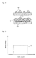
- Sugiura et al. propose a window type scattering characteristic such that the intensity of reflected light is constant within a certain angle range (see solid line 62 in Fig. 21) as a scattering characteristic that realizes higher brightness in a wide viewing angle range, and as a shape capable of realizing such a scattering characteristic, Sugiura et al. propose a method whereby a continuous curved surface 65 is formed such that convex-down quadratic functions 63 and convex-up quadratic functions 64 are joined together as shown in Fig. 22 (see, for example, AM-LCD '95, Digest of Technical Papers, pages 153-156, Norio Sugiura and Tatuso Uchida, August 1995).
- the reflected light intensity is highest in the directions of specular reflection and the exit angle dependency is high.
- display may appear metallic.
- the window type scattering characteristic may make a preferable countermeasure for these problems
- the continuous curved surface defined by quadratic functions (those shown in Fig. 22) proposed by Sugiura et al. are defined two-dimensionally as is understood from the equation, and the scattering direction is limited to one direction.
- each of the depressions and protrusions has a vertex and is composed of a curved surface formed so as to be convex up or convex down and a surrounding portion including a valley or a ridge surrounding the curved surface with an inflection point of the curved surface serving as a boundary between the curved surface and the surrounding portion, and when the curved surface is convex up, the inflection point is on the valley side of the midpoint between the vertex and the valley, whereas when the curved surface is convex down, the inflection point is on the ridge side of the midpoint between the vertex and the ridge.
- the average value of "a" for the protrusions is fixed to be greater than 2 and equal to or less than 4.
- each curved surface of such a reflector have a width two or more times the width of the surrounding portion.
- the average value of "a" greater than 2 and equal to or less than 3 and the intensity of reflected light that is reflected by the reflector such that light in a direction of specular reflection of incident light has a higher intensity than diffusely reflected light in a direction of scattering of incident light at a specified reflection angle, it is possible to realize an unprecedented reflection characteristic such that the viewing angle direction is even brighter than the specular reflection direction.
- a second reflector of the present invention having a reflecting film formed on a surface with a plurality of depressions and protrusions made up of a continuous curved surface
- the average value of "a" for the plurality of depressions and protrusions is fixed to be greater than 2.5 and less than 3.5.
- a display element and a display device incorporating a reflector such as the above-described second reflector, it is possible to provide bright displays with a wide viewing angle at low power consumption, as is the case with the first reflector.
- a method of producing a reflector of the present invention comprises the steps of forming first protrusions or depressions on a substrate surface, forming second protrusions or depressions by performing exposure with a photomask and development on portions where the first protrusions or depressions are not present, and forming a reflecting film on the second protrusions or depressions.
- a second method of producing a reflector of the present invention comprises the steps of forming a plurality of depressions each having a curved-like surface and being separated from one another on at least a portion of a substrate surface having pixel portions, and widening the diameter of each of the plurality of depressions until adjacent depressions are dose to one another by substantially isotropically etching the substrate surface.
- the reflector and the reflective liquid crystal display element of the present invention are capable of realizing bright displays with a wider range of viewing angles (including the range where the exit angles are - 5 degrees to 5 degrees) than have been achieved in the past. Further, there was no dependency on the direction of incident light.
- the convex shape is not necessarily limited to a solid of revolution and many variations are possible as long as the cross section is a curved surface with a degree of two or less, a pyramid having several sides and a curved surface-like cross section being acceptable.
- Equation 2 is curve fitted, where z represents the thickness direction and x represents the horizontal direction from the extreme values of the cross-sectional shape of each protrusion or depression, and ⁇ and ⁇ represent constants
- the characteristic is transformed from the window type into the triangle type.
- Embodiments 1 to 4 are inverted so that the diffuse reflection characteristic is the window type scattering characteristic. Further to prevent scattering reflected light from being colored due to diffraction effect, it is necessary to arrange the protrusions irregularly or arrange them linearly and irregularly in position.
Landscapes
- Physics & Mathematics (AREA)
- General Physics & Mathematics (AREA)
- Optics & Photonics (AREA)
- Nonlinear Science (AREA)
- Mathematical Physics (AREA)
- Chemical & Material Sciences (AREA)
- Crystallography & Structural Chemistry (AREA)
- Optical Elements Other Than Lenses (AREA)
- Liquid Crystal (AREA)
Abstract
In a reflector comprising a reflecting film formed on a surface having
depressions and protrusions, wherein each of the depressions and
protrusions has a vertex and is composed of a curved surface formed so as to
be convex up or convex down and a surrounding portion including a valley
or a ridge surrounding the curved surface with an inflection point of the
curved surface serving as a boundary between the curved surface and the
surrounding portion; and wherein when the curved surface is convex up, the
inflection point is on the valley side of the midpoint between the vertex and
the valley, whereas when the curved surface is convex down, the inflection
point is on the ridge side of the midpoint between the vertex and the ridge.
Description
The present invention relates to a reflector, a production method
thereof, a display element, and a display device, and more particularly, to a
reflective display element and a reflective display device in which a
non-emissive light modulating layer is employed.
A liquid crystal display, which is a typical example of a non-emissive
display element, is categorized into a transmissive liquid crystal display in
which a backlight is disposed at the back and a reflective liquid crystal
display in which a reflector is disposed at the back to utilize external light
for illumination. However, the reflective liquid crystal element is
advantageous in that a liquid crystal can be driven at a low voltage of a few
volts, and thus operation is realized with extremely low power consumption.
In the case of the reflective liquid crystal element, a diffuse reflector made of
aluminum or silver is disposed behind the liquid crystal layer, while in the
case of a black-and-white reflective liquid crystal incorporated into, for
example, a watch, configuration is such that a diffuse reflector having a
polarizer is attached to the outside of the glass.
In Japanese Unexamined Patent Publication No. 4-243226, in order to
fabricate a diffuse reflector whose shape can be controlled with good
reproducibility on the inner surface of the glass, a diffuse reflecting film is
fabricated as follows. As shown in Fig. 19, a resist film 52 is coated on a
glass substrate 51 and is exposed to light exposure through a photomask 53,
and after a plurality of protrusions 54 spaced apart from one another are
formed, the edges of each protrusion are rounded by performing a heat
treatment, and then over the structure, a metal reflecting film 56 is formed.
In Japanese Unexamined Patent Publication No. 6-27481, in order to
prevent interference colors from being generated by flat portions that are
not patterned as disclosed in the above-mentioned Japanese Unexamined
Patent Publication No. 4-243226, protrusions 60 are coated with a polymeric
resin 61 to form smooth and continuous depressions and protrusions as
shown in Fig. 20.
Sugiura et al. propose a window type scattering characteristic such
that the intensity of reflected light is constant within a certain angle range
(see solid line 62 in Fig. 21) as a scattering characteristic that realizes
higher brightness in a wide viewing angle range, and as a shape capable of
realizing such a scattering characteristic, Sugiura et al. propose a method
whereby a continuous curved surface 65 is formed such that convex-down
quadratic functions 63 and convex-up quadratic functions 64 are joined
together as shown in Fig. 22 (see, for example, AM-LCD '95, Digest of
Technical Papers, pages 153-156, Norio Sugiura and Tatuso Uchida, August
1995).
However, with the prior art reflectors in which a reflecting film is
provided on the protrusions spaced apart from one another or is provided on
the continuous curved surface formed by leveling off the protrusions spaced
apart from one another with a resin (as shown in Fig. 20), the reflected light
intensity is highest in the directions of specular reflection and the exit angle
dependency is high. This creates problems for the reflection characteristics,
for example, display may appear metallic. Although the window type
scattering characteristic may make a preferable countermeasure for these
problems, the continuous curved surface defined by quadratic functions
(those shown in Fig. 22) proposed by Sugiura et al. are defined
two-dimensionally as is understood from the equation, and the scattering
direction is limited to one direction. Therefore, scattering does not occur
with respect to light entering from a direction orthogonal to this direction,
and thus the continuous curved surface offers no practical use.
Consequently, at the present, a window type scattering characteristic with a
small amount of direction dependency is yet to be realized, and a
three-dimensional shape for a reflector having depressions and protrusions
that show such characteristics is desired.
In view of the foregoing problems, it is one of the objects of the present
invention to realize a window type scattering characteristic with a small
amount of direction dependency by improving a reflector and to provide a
display element and a display device in which bright displays with a wide
range of viewing angles as well as paper white displays free from sense of
metallicity are possible.
It is another object of the present invention to provide a method of
easily producing the aforementioned reflector, display element, and display
device.
In order to solve the foregoing problems, in a first reflector of the
present invention comprising a reflecting film formed on a surface having
depressions and protrusions, each of the depressions and protrusions has a
vertex and is composed of a curved surface formed so as to be convex up or
convex down and a surrounding portion including a valley or a ridge
surrounding the curved surface with an inflection point of the curved
surface serving as a boundary between the curved surface and the
surrounding portion, and when the curved surface is convex up, the
inflection point is on the valley side of the midpoint between the vertex and
the valley, whereas when the curved surface is convex down, the inflection
point is on the ridge side of the midpoint between the vertex and the ridge.
Preferably, when cross-sectional shapes of the curved surfaces are
made similar by defining the cross-sectional shapes by z = αxa/2 + β, where z
is the thickness direction, x is the horizontal direction, and α and β are
constants, the average value of "a" for the protrusions is fixed to be greater
than 2 and equal to or less than 4.
By using a reflector having such a configuration, it is possible to
realize a window type scattering characteristic with a small amount of
direction dependency, thereby enabling the provision of bright displays with
a wide viewing angle.
In addition, it is preferable that each curved surface of such a reflector
have a width two or more times the width of the surrounding portion.
Furthermore, by making the average value of "a" greater than 2 and
equal to or less than 3 and the intensity of reflected light that is reflected by
the reflector such that light in a direction of specular reflection of incident
light has a higher intensity than diffusely reflected light in a direction of
scattering of incident light at a specified reflection angle, it is possible to
realize an unprecedented reflection characteristic such that the viewing
angle direction is even brighter than the specular reflection direction.
Additionally, when adjacent convex up or convex down curved surfaces
are close to one another and there are substantially no surrounding portions,
specular reflected light is suppressed more, and thus easily viewable
displays can be obtained. It is especially easy to produce a shape such that
the shape having depressions and protrusions comprises only either convex
up or convex down and the sign of the slope of inclined surfaces of adjacent
protrusions is reversed at every boundary between the depressions or
protrusions
In a second reflector of the present invention having a reflecting film
formed on a surface with a plurality of depressions and protrusions made up
of a continuous curved surface, when cross-sectional shapes having vertexes
of the depressions or the protrusions as origins are made similar by defining
the cross-sectional shapes by z = αxa/2 + β, where z is the thickness direction,
x is the horizontal direction, and α and β are constants, the average value of
"a" for the plurality of depressions and protrusions is fixed to be greater
than 2.5 and less than 3.5.
In a display element and a display device incorporating a reflector
such as the above-described second reflector, it is possible to provide bright
displays with a wide viewing angle at low power consumption, as is the case
with the first reflector.
Furthermore, a liquid crystal display element of the present invention
comprises a substrate and a liquid crystal layer, the substrate having a
plurality of convex-up or convex-down curved surfaces each having a vertex,
a reflecting film on the convex curved surfaces, and no reflecting film on
surrounding portions surrounding the convex curved surfaces, wherein
when cross-sectional shapes having vertexes of the convex curved surfaces
as origins are made similar by defining the cross-sectional shapes by z =
αxa/2 + β, where z is the thickness direction, x is the horizontal direction, and
α and β are constants, the average value of "a" for the plurality of
protrusions or depressions is fixed to be greater than 2 and equal to or less
than 4. With such a liquid crystal display element, it is possible to realize
a transflective liquid crystal display element having the characteristic of the
first or second reflector described above.
A method of producing a reflector of the present invention comprises
the steps of forming first protrusions or depressions on a substrate surface,
forming second protrusions or depressions by performing exposure with a
photomask and development on portions where the first protrusions or
depressions are not present, and forming a reflecting film on the second
protrusions or depressions.
By using the method, it is possible to produce the above-mentioned
reflector.
A second method of producing a reflector of the present invention
comprises the steps of forming a plurality of depressions each having a
curved-like surface and being separated from one another on at least a
portion of a substrate surface having pixel portions, and widening the
diameter of each of the plurality of depressions until adjacent depressions
are dose to one another by substantially isotropically etching the substrate
surface.
By using the method, it is possible to produce the above-mentioned
reflector with few steps.
A third method of producing a reflector of the present invention
comprises the steps forming a photoresist film having a plurality of holes on
at least a portion of a substrate surface having pixel portions by
photolithography, and by substantially isotropically etching the substrate
surface, forming depressions with a larger diameter than the holes in the
holes on the substrate surface, so that a plurality of depressions adjacent to
one another are made close.
By using the method, it is possible to easily produce the
above-mentioned reflector.
In addition, a resin film of the present invention is such that a
photosensitive resin layer is coated on a base film having a surface with a
plurality of protrusions or depressions each having a curved-like surface.
By using the resin film, the formation of a reflector having depressions
and protrusions on the substrate surface of a display element is facilitated.
In order that the above-mentioned depressions and protrusions be
suitable for a diffuse reflector, it is preferable that white scattering be
caused by the protrusions or depressions when the average value for the
maximum inclination angle of each of the plurality of protrusions or
depressions having a curved-like surface is not less than 2° and not more
than 15°, and more preferably, not less than 4° and not more than 11°.
Each of the protrusions or depressions is composed of a convex up or
convex down curved surface having a vertex and a surrounding portion
including a ridge or a valley surrounding the curved surface with an
inflection point of the curved surface serving as a boundary between the
curved surface and the surrounding portion, and wherein when the curved
surface is convex up, the inflection point is on the valley side of the midpoint
between the vertex point and the valley, whereas when the curved surface is
convex down, the inflection point is on the ridge side of the midpoint
between the vertex and the peak. Or, when cross-sectional shapes having
vertexes of the depressions or the protrusions as origins are made similar by
defining the cross-sectional shapes by z = αxa/2 + β, where z is the thickness
direction, x is the horizontal direction, and α and β are constants, the
average value of "a" for the plurality of depressions and protrusions is fixed
to be greater than 2 and less than 4. This way, the characteristic of the
first reflector of the present invention is realized.
A resin film of the present invention is easily produced by using a
method comprising the steps of forming a plurality of protrusions or
depressions each having a curved-like surface in a surface of a base film
with a molding tool, and coating a photosensitive resin layer on the base
film.
Further, by a method of producing a reflector in which by laminating
on a substrate a reflecting film fabricated such that a resin film in which a
photosensitive resin layer is coated on a base film that has a surface with a
plurality of protrusions or depressions each having a curved-like surface,
and by transferring the photosensitive resin film that has a surface with a
plurality of depressions and protrusions onto the substrate, to form a
reflecting film on the photosensitive resin layer, it is possible to produce a
reflector using a resin film of the present invention with a simple
manufacturing process, thereby making it possible to reduce losses arising
from process defects.
In particular, by a method of producing a reflector in which a substrate
has TFT devices and after a photosensitive resin is transferred, contact
holes are formed in the photosensitive resin above output terminals of the
TFT devices, the advantageous effect of a reduction in losses is great.
As is obvious from the figures, each depression is cone-like and has a
substantially quadratic surface. Specifically, the surface shape of each
depression can be expressed by the following Equation 1, where the z axis is
in the vertical direction, the x and y axes are within the substrate plane,
and the origin is on the bottom of the cone-like depression (the vertex).
z = α(x2 + y2 ) + β
A cross-sectional shape of the surface shape is expressed by Equation 2
described below (in Equation 1, y = 0). It should be noted that the average
value of the "a" in Equation 2 for a large number of the depressions is 4.
z = αxa/2 + β
Note that in both Equations 1 and 2, reference characters α and β
denote constants. The value of α varies according to the diameter or the
depth of each depression, and the value of β indicates the height of the
bottom, the origin of each depression. The depth, diameter, and positioning
of the depressions are made irregular in order to avoid coloring caused by
diffraction effects and to generate white light scattering, and therefore while
the constants α and β are variable, the degree of Equation 2 is relatively
stable. Note that the average value of the degree (the average value of a/2
in Equation 2) is an average value determined by curvefitting a cross section
of each depression.
In addition, since the diameter of each depression must be smaller
than at least the pixel size, it is preferable that the diameter of each
depression be 50 µm or less. It is preferable, however, that the diameter of
each depression be at least 3 µm because when the diameter of each
depression is made too small, the problems of an intensifying in coloring
caused by diffraction and a decreasing process margin arise.
As is clear from Fig. 2, a middle recession 1A with a large diameter is
made deep and a right depression 1B is made shallow, and angles of
inclination formed at the boundary portion between the depressions, where
inclination is steepest, are made to be approximately 11 degrees. This
makes the depressions substantially similar to one another in shape.
Furthermore, by fixing the inclination angles formed at boundary portions,
where inclination is steepest, in the above-described manner, for example, at
the boundary between the depression 1A and the depression 1B, by fixing
the inclination angle in a direction increasing to the right to be 11 degrees
and the inclination angle in a direction decreasing to the right to be 11
degrees, the slopes of the depressions are discontinuous and the sign of
slope reverses back and forth.
A comparative example was prepared following Japanese Unexamined
Patent Publication No. 6-27481 that was previously mentioned in
Background Art, and it is illustrated in Fig. 3 and Fig. 4. Fig. 3 is a plan
view and Fig. 4 is a cross-sectional view taken along the chain line of Fig. 3.
As is obvious from Fig. 4, in a reflector of the comparative example, there is
formed a continuous curved line, and the continuous curved line has a
configuration approximate to the shape of convex-up and convex-down
quadratic functions joined together.
An aluminum reflecting film was deposited to a thickness of 200 nm
over the quadratic surfaces of the present invention having discontinuous
boundaries shown in Fig. 1 and over the continuous curved surface of the
prior art shown in Fig. 3, respectively, to form reflectors. Then with a
liquid crystal sandwiched between the substrate and a counter substrate,
the respective diffuse reflection characteristics were measured and the
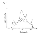
results are shown in Fig. 5. Fig. 5 shows the measured exit angle
dependency of reflected light when a light beam was projected at an angle of
minus 30 degrees from a direction normal to the substrate. In Fig. 5, the
exit angle is plotted on the horizontal axis and light intensity is plotted on
the vertical axis.
As is clear from Fig. 5, a characteristic curve 10 of the reflector of the
present invention shows a window type characteristic such that light
intensity is substantially constant when exit angle is in the range of 30 ±
approximately 35 degrees. This is due to the fact that the maximum
inclination angle formed at each depression corresponds to the scattering
angle of diffuse reflection, and thus, by ensuring that the maximum
inclination angles are uniformly about 11 degrees, the brightness rapidly
increases when the scattering angles are in the range of 35 degrees or less.
By contrast, a characteristic curve 9 of the conventional continuous
curved surface shows a triangle type characteristic such that the highest
intensity is zero when exit angle is 30 ± about 40 degrees, and the highest
light intensity is observed in the direction of specular reflection. Reflective
panels, when actually viewed, are generally viewed from an angle about 25
degrees to 35 degrees from the specular reflection direction, because
viewability deteriorates at angles near specular reflection as a result of
reflection of light. Therefore, in Fig. 5, the display brightness is mostly
determined by light intensity in the vicinity of the front panel where the exit
angles are from about - 5 degrees to 5 degrees. As is understood from Fig.
5, it has been proved that the reflector and the reflective liquid crystal
display element of the present invention are capable of realizing bright
displays with a wider range of viewing angles (including the range where
the exit angles are - 5 degrees to 5 degrees) than have been achieved in the
past. Further, there was no dependency on the direction of incident light.
Because the greater the scattering angle the more light is diffused and
intensity weakened, the window type characteristic cannot be realized
unless the area of the inclined surfaces having steep inclinations is made
larger with increase in the inclination angle. However, because the prior
art reflector of Fig. 3 comprises shapes that have substantially quadratic
surfaces, flat portions where the inclination is gentle occupy a large area
including not only the vertexes of the protrusions but also the valley bottom
portions (the hatched portions) formed at the foot of each protrusion
surrounding the protrusions, and thus the area of the flat portions is larger
than the area of the inclined surfaces having steep inclinations. As a result,
the closer the reflected light intensity is to the specular reflection angle as
shown in the characteristic curve 9, the more light intensity increases.
In view of the above, the inventors of the present invention,
recognizing that the proposal made by Sugiura et al. of depressions or
protrusions that are quadratic surfaces is insufficient, discovered that it is
necessary to make the flat portions of the foot portions surrounding the
depressions or the protrusions as small as possible in order to realize the
window type characteristic. Consequently, the inventors of the present
invention adopted a configuration such that depressions or protrusions each
having a quadratic surface are close to one another and, for example as
shown in Figs. 1 and 2, the inclinations at the boundary portions are
discontinuous. This configuration made it possible to produce a reflector
with a wide viewing angle and high brightness.
It is to be noted that although it is necessary that there be a degree of
disorder in the size or position of each of the depressions or protrusions in
order to prevent colors caused by diffraction, as in the present embodiment,
even if the size varies, the depressions or protrusions (quadratic surfaces)
are preferred to have substantially uniform maximum inclination angles
because a characteristic that is more similar to the window type
characteristic results.
However, in the case of curved surfaces having a degree lower than two,
as long as curved surfaces have a degree equal to or less than two and
greater than 1, which forms a linear line, it is possible to realize a similar
characteristic. This will be explained in the following Experiment 2.
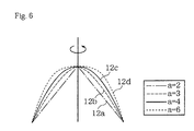
Taking a convex shape having a cross-sectional shape that is a curve
defined by Equation 2 and comprising a solid of revolution formed by
rotating such a cross-sectional shape about its vertex, cross-sectional shapes
of convex shapes when the degree of Equation 2 is changed by substituting
"a" with 2, 3, 4, and 6, respectively, were simulated, and the results are
shown in Fig. 6. Note that in Fig. 6, curves obtained when a = 2, 3, 4, and 6
are represented by curves 12a, 12b, 12c, and 12d, respectively.
In addition, a reflecting film was formed on these protrusions, and
the results of calculating diffuse reflection characteristics obtained when
light was projected at an angle of 30 degrees as with the above-described
Experiment 1 were shown qualitatively in the graph showing the
characteristics of Fig. 7. Note that in Fig. 7, reference characters 13a, 13b,
13c, and 13d correspond to the above-mentioned curves 12a, 12b, 12c, and
12d.
As is clear from these figures, when a = 4 in Equation 2 (that is, in the
case of a quadratic surface), a window type scattering characteristic like
that of the solid line 13c is obtained. When a = 3, the obtained shape is like
that of the broken line 13b indicating that the reflection is stronger in the
scattering direction than in the specular direction, and it was revealed that
an unprecedented characteristic such that the viewing angle direction is
even brighter than it is in the case of the window type scattering
characteristic is obtained. On the other hand, when a = 2, a cone having an
inclined surface defined by linear lines is obtained, and thus a characteristic
such as that of the dashed line 13a indicating that reflection occurs only in
the direction of a specific polar angle results. When a = 6, it was revealed
that a characteristic similar to the conventional scattering characteristic
that shows a stronger reflection in the specular direction, such as that of
13d, is obtained.
The above-described calculated results were obtained from light
reflected off one convex shape. It has been discovered, however, that in the
case of a reflector surface having a plurality of protrusions formed thereon,
the characteristic can be roughly determined by summing the
characteristics of each convex shape (there may be slight difference
depending on diffraction effects). Hence, when a reflector surface has
formed thereon a plurality of protrusions that are similar to one another in
shape, it is possible to obtain a characteristic similar to the one obtained in
this experiment, whereas when a reflector surface has formed thereon a
variety of shapes having differing slopes, a different characteristic is
obtained. For example, when the reflector surface has a shape capable of
achieving the peak-like reflection characteristic 13a obtained when a = 2,
the same characteristic as that when a = 4 may be obtained by employing a
distribution such that with inclination angle of a plurality of protrusions
within the range of the window type characteristic, the number of
protrusions is increased as the degree of inclination angle increases. Even
when a = 3, distribution control makes it possible to obtain the same
outcome. On the contrary, when the reflector is composed of curved
surfaces with a degree obtained when a = 6, it is theoretically impossible to
achieve a window type characteristic such as the one obtained when a = 4
when the degree is small. Thus, a curved surface having a degree greater
than two results in the conventional scattering characteristic of strong
specular reflection and is not preferable; therefore, a cross-sectional shape
such that a degree greater than that obtained when a = 2 and equal to or
less than that obtained when a = 4 is preferred.
It should be noted that the convex shape is not necessarily limited to a
solid of revolution and many variations are possible as long as the cross
section is a curved surface with a degree of two or less, a pyramid having
several sides and a curved surface-like cross section being acceptable.
Method of fabricating reflectors
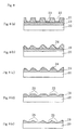
The reflector illustrated in Fig. 1 was manufactured in the following
manner, which is explained with reference to Fig. 8.
Firstly, as shown in Fig. 8(a), on a substrate 20 having a SiNx film 19
with a thickness of 600 nm deposited thereon, an acrylic positive resist 21
was coated to a thickness of 4 µm and subsequently holes 22 each having a
diameter of 3-5 µm were photolithographically formed (at average intervals
of approximately 3 µm) so as to leave a remainder film 23 having a
thickness of about 0.5 µm under the holes 22. Then by heating the
substrate 20 at 130°C for ten minutes using a hotplate, smooth depressions
and protrusions 24 as shown in Fig. 8(b) were formed. Reactive ion etching
was performed, using a mixed gas of 75% CF4 and 25% O2, on the surface of
the substrate. In this case, the positive resist 21 and the SiNx film 19 were
etched at an etching rate of about 5 to 1. The etching was stopped when
half of the positive resist film 21 remained as shown in Fig. 8(c), and then
the positive resist film 21 was removed. Thus, only depressions 25
remained as shown in Fig. 8(d). Subsequently, the SiNx film 19 was
isotropically etched by plasma etching using a mixed gas of 90% CF4 and
10% O2. This caused the diameter of the holes 25 to widen, and thereby the
edges of adjacent depressions to contact one another as shown in Fig. 8(e).
In this manner, a reflector having the shape illustrated in a plan view of Fig.
1 was manufactured.
The production method is not limited to the above-described one and,
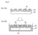
for example, the production method illustrated in Fig. 9 is acceptable. That
is, as shown in Fig. 9(a), on a substrate 20 on which an Al film 26 is
deposited to a thickness of 600 nm, a plurality of holes each having a
diameter of 2 µm were photolithographically formed to an average pitch of 4
µm in a novolak type regular positive resist 27. Then as shown in Fig. 9(b),
when the aluminum was removed by wet etching in an aluminum etchant
28 in which phosphoric acid, acetic acid, nitric acid, and water were mixed,
the etchant entered portions underneath the resist at the periphery of each
hole and etching progressed. As a result, a shape similar to the one of Fig.
1 in which adjacent depressions 29 are in contact with one another was
formed on the Al film 26. Even with this film having depressions and
protrusions, a similar window type characteristic was realized. However,
there was non-uniformity in the substrate surface.
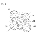
Fig. 12 is a plan view of a reflector of Embodiment 2 of the present
invention. Such a reflector was fabricated as follows.
First, on a substrate, a first acrylic positive resist film was
photolithographically patterned to form circular protrusions 30, and the
protrusions were melted with heat to round the vertexes. When a second
resist film was subsequently coated over the protrusions and was
exposed/developed using a mask having a pattern that is the
positive-negative inverse of the first resist film formed therein, the resist
was left on portions other than the round protrusions. By rounding the
resist with heat to form second protrusions 31 in the same manner as that
of the first film, the cross section became such that adjacent protrusions
were close to one another and flat portions at the foot of each protrusion
were substantially eliminated, whereby the cross section took on a shape
having an inclination angle formed at each boundary that varied
discontinuously, as shown in Fig. 13.
Note that the first and the second resist films had a thickness of 0.8
µm and the diameter of each of the circular protrusions was about 6 µm.
Over the above-mentioned depressions and protrusions, an aluminum
reflecting film was deposited to a thickness of 200 nm to form a reflector,
and then the diffuse reflection characteristics of the reflector was measured.
The results are shown in Fig. 5 that was previously discussed. It is to be
noted that the methods of carrying out the experiment and the
measurement are similar to those of Experiment 1 in Embodiment 1.
As is apparent from Fig. 5, the diffuse reflection characteristics of a
reflector of the present invention that is represented by a solid line 11 shows
a higher intensity of exiting light at an angle of about 0 degree in
comparison with the characteristic curve 9 of the conventional reflector, and
thereby the reflector of the present invention proved to be capable of
improving viewing angle as well as brightness.
A plan view of a second reflector of the present invention is shown in
Fig. 14. In Fig. 14, a solid line 32 represents the ridge portion of ribbed
depressions and protrusions and a broken line 33 represents a valley portion.
As shown in Fig. 14, the lines representing the ribbed depressions and
protrusions point in various directions as in a fingerprint, and the distance
between the ridges is 10 ± 1 µm. The distance varies by small amounts
depending on the spot, and this serves to prevent the appearance of
interference colors.
According to Sugiura et al. referred to in Background Art, the ribbed
depressions and protrusions whose cross section is a quadratic curve were
formed in one direction, and thus scattering occurred only in one direction.
In consideration of this, in Embodiment 3, the ribbed depressions and
protrusions were curved into the shape of a fingerprint in order to resolve
the direction dependency. However, when such a ribbed pattern was
formed using the method disclosed in Japanese Unexamined Patent
Publication No. 6-27481 that was referred to in Background Art, though the
cross-sectional shape was like that of a quadratic curve, the reflection
characteristic was a triangle type resembling the characteristic curve 11 of
Fig. 5, a characteristic having high angle dependency.
In consideration of the above, from the cross-sectional shape of the
ribbed depressions and protrusions that are whorl-shaped, shape models
each slightly different were formed using a cutting process, and the
reflection characteristics were observed.
As a result, it became clear that when Equation 2 is curve fitted,
where z represents the thickness direction and x represents the horizontal
direction from the extreme values of the cross-sectional shape of each
protrusion or depression, and α and β represent constants, the reflection
characteristic is a window type characteristic in the case of a = 3. As the
value of the "a" increases from 3 to 4, the characteristic is transformed from
the window type into the triangle type. In the case of a = 2, that is, when
the inclination is linear, the scattering angle becomes extremely small, but
the scattering angle can be substantially controlled by providing a
distribution in inclination in accordance with position, and therefore it is
possible to obtain a characteristic similar to the window type characteristic.
However, it was found that when the value of the "a" exceeds 3, no
improvement can be realized by providing a distribution.
For the reason described above, in the case of ribbed depressions and
protrusions with little direction dependency that are curved so as to form a
curved line, when the cross-sectional shapes are made similar to one
another, a preferable characteristic, the window type characteristic, can be
realized when the value of the "a" in Equation 2 is from about 2 to 3.
It should be noted that in cases where the ribbed depressions and
protrusions are mixed with discontinuous cone-like depressions or
protrusions such as those of Embodiment 2, it is preferable to set the value
of the "a" in Equation 2 in the range of 3 to 4 for the ridged depressions and
protrusions in accordance with the mixing ratio.
Although a cutting process was employed to form the models in
consideration of the shapes, the following method involving a
photolithography process was employed in order to realize mass production
of actual reflectors.
As in the past, shape approximates a quadratic curve-type with
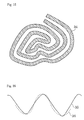
melting by heat. Therefore, as shown in Fig. 15, by using a mask on which
a curved light-shielding pattern 34 corresponding to the valleys of the ribs is
formed, a positive resist coated on the substrate to a thickness of 0.6 µm
was subjected to a proximity exposure. The line width and spaces of the
light-shielding pattern were 3 µm, and the proximity gap was 50 µm. With
such a gap, due to diffraction, a realizable resolution by photolithography
was approximately 5 µm. Because the resolution of the light-shielding
pattern of Fig. 15 fell under the resolution limit, the mask image was
blurred and the pattern that resulted from the development had a shape
close to that of a solid line 35 of Fig. 16 where x is raised to the 3/2th power
(see Equation 2 described above). For the sake of comparison, a curve 36
where z = x2 is shown by a dashed line, and it became clear that the curve
where x is to the 3/2th power has a shape between a line and a quadratic
curve. Subsequently, the above resist was polymerized at a temperature of
200°C and further an aluminum film was deposited, and as a result, a
reflector having a window type characteristic nearly identical to that of
Embodiment 1 was obtained.
A reflective liquid crystal display element fabricated by sealing
together such a reflector and a counter substrate is capable of bright,
wide-angle, and high quality displays that may be perceived the way a sheet
of paper is; therefore, a display device having excellent display
characteristics is realized.
It became evident from simulation that even when a reflector has a
shape other than the ribbed one as described above and has a shape
comprising a continuous curved surface as shown in Fig. 3, it is possible to
achieve the window type characteristic, as long as the degree of the
cross-sectional shape decreases from that of a quadratic surface to that of a
curved surface with a power of 3/2 forming a line like the solid line 35 of Fig.
16. It was observed that the degree is not strictly limited to 3/2, and as
long as the value of the "a" in Equation 2 is in the range of 2.5 to 3.5, it is
possible to obtain a characteristic more similar to the window type
characteristic in comparison that has been obtained in the past.
Though Embodiments 1 to 3 discuss a reflective liquid crystal,
Embodiment 4 discusses a transflective liquid crystal display element
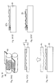
having the window type scattering characteristic. Fig. 17 is a
cross-sectional view showing a transflective liquid crystal display element of
Embodiment 4 of the present invention. Depressions and protrusions may
be similar to the conventional ones shown in Fig. 3. A reflecting film 38 is
formed only on the protrusion surfaces 37 each having a vertex of the
depressions and protrusions, and the reflecting film 38 is removed from the
surrounding portions to make the surrounding portions light-transmissive.
Over this, a transparent electrode 39 made of ITO was subsequently formed.
Since the reflection characteristic applies only to the protrusion portions
having the reflecting film, and not to the surrounding portions, it is possible
to improve the reflection characteristic to be close to the window type
scattering characteristic having a wide viewing angle. The substrate and
counter substrate 41 are sealed together with a liquid crystal 40 sandwiched
therebetween, and then polarizers 42a and 42b each provided with a
retardation film are attached to the front and the back surfaces, respectively.
A transflective liquid crystal panel 43 is thus fabricated.
In the transflective liquid crystal display element fabricated using the
method described above, the transmitted light from a backlight 44 passes
through portions on which no reflecting film is formed, thereby permitting
display in dark conditions.
It should be noted that the shape having depressions and protrusions
is not limited to the conventional continuous quadratic surfaces of Fig. 3
and may be such that the surrounding portions are narrow as shown in Fig.
8 and Fig. 9, but it is necessary in both cases to leave the reflecting film only
on the convex-up and convex-down quadratic surface portions having the
vertexes and to make the rest of the portions light-transmissive. With such
a configuration, a transflective liquid crystal element having a diffuse
reflection characteristic with brightness and a wide viewing angle is
realized.
Embodiment 5 relates to a resin film with which a reflector having
depressions and protrusions of the present invention can be fabricated at
low cost, a production method thereof, and a method of producing a reflector
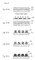
by using the resin film. Fig. 18 shows views illustrating the steps of the
method of producing a resin film and a reflector using the resin film in
accordance with the present invention.
First, as shown in Fig. 18(a), a die 46 having a roll shape and having
depressions and protrusions inscribed thereon is stamped onto one of the
surfaces of a base film 45 (thickness is 50 µm) made of polyethylene
terephthalate (PET) to form a plurality of depressions and protrusions. It
is preferable that these depressions and protrusions be suitable for a diffuse
reflector, that is, that inclination angle of these depressions and protrusions
for providing a moderate amount of diffuse reflection be such that the
maximum inclination angle of the depressions and protrusions is in the
range of 2° to 15°, and more preferably, in the range of 4° to 11°. It is most
preferred to employ a shape where the depressions and protrusions of
Embodiments 1 to 4 are inverted so that the diffuse reflection characteristic
is the window type scattering characteristic. Further to prevent scattering
reflected light from being colored due to diffraction effect, it is necessary to
arrange the protrusions irregularly or arrange them linearly and irregularly
in position.
Subsequently, as shown in Fig. 18(b), a photosensitive resin 47 is
coated on the base film having the depressions and protrusions formed
thereon to a thickness of about several micrometers by a slit coater, and
after covering the base film with a protective sheet, a resin film 48 (dry film
resist) that is curled into a roll-shape is fabricated. As shown in Fig. 18(c),
after the above-described resin film is laminated over a driving substrate 49
for use in a display panel including TFT devices by an ordinary method, the
base film 45 having formed thereon the depressions and protrusions
suitable for a reflector is removed such that the photosensitive resin layer
47 is formed on a surface of the driving substrate 49.
Next, by photolithographycally forming a contact hole 47h in the
photosensitive resin that is on a TFT device as shown in Fig. 18(d), and
further by forming a reflective electrode 50 made of an aluminum alloy as
shown in Fig. 18(e), the TFT and the reflective electrode are electrically
connected.
As discussed above, according to the present Embodiment 5, the
depressions and protrusions suitable for a reflector can be fabricated on a
substrate by laminating a resin film in which depressions and protrusions
have been formed in a base film with a molding tool.
Moreover, since the number of processing steps involved in the driving
substrate for use in a display panel does not increase as has been the case in
the past, the manufacturing cost is remarkably decreased. This is because
the driving substrate, having undergone a number of processing steps, is a
high-value-added product, and hence, when the step of forming the
depressions and protrusions for a reflector is omitted, for example, losses
caused by a decrease in a yield are reduced.
It should be noted that when a photosensitive resin is employed as the
resin, the formation of the contact hole is facilitated.
In a reflector and a liquid crystal display element of the present
invention, bright displays with a wide viewing angle and paper white
displays without a sense of metallicity are realized. In addition, such a
useful reflector and a liquid crystal display element is easily produced, and
thus the value to industry is great.
Claims (33)
- A reflector comprising a reflecting film formed on a surface having depressions and protrusions wherein:each of the depressions and protrusions has a vertex and is composed of a curved surface formed so as to be convex up or convex down and a surrounding portion including a valley or a ridge surrounding the curved surface with an inflection point of the curved surface serving as a boundary between the curved surface and the surrounding portion; and wherein when the curved surface is convex up, the inflection point is on the valley side of the midpoint between the vertex and the valley, whereas when the curved surface is convex down, the inflection point is on the ridge side of the midpoint between the vertex and the ridge.
- The reflector according to claim 1, wherein, when cross-sectional shapes of the curved surfaces are made similar by defining the cross-sectional shapes by z = αxa/2 + β, where z is the thickness direction, x is the horizontal direction, and α and β are constants, the average value of "a" for the protrusions is fixed to be greater than 2 and equal to or less than 4.
- The reflector according to claim 2, wherein each curved surface has a width two or more times the width of the surrounding portion.
- The reflector according to claim 3, wherein the average value of "a" is greater than 2 and equal to or less than 3 and the intensity of reflected light that is reflected by the reflector is such that light in a direction of specular reflection of incident light has a higher intensity than diffusely reflected light in a direction of scattering of incident light at a specified reflection angle.
- The reflector according to claim 1, wherein adjacent convex up or convex down curved surfaces are close to one another and there are substantially no surrounding portions.
- The reflector according to claim 2, wherein adjacent convex up or convex down curved surfaces are close to one another and there are substantially no surrounding portions.
- The reflector according to claim 5, wherein the shape having depressions and protrusions comprises only either convex up or convex down and the sign of the slope of inclined surfaces of adjacent protrusions is reversed at every boundary between the depressions or protrusions.
- The reflector according to claim 6, wherein the shape having depressions and protrusions comprises only either convex up or convex down and the sign of the slope of inclined surfaces of adjacent protrusions is reversed at every boundary between the depressions or protrusions.
- A display element comprising a reflector according to claim 1.
- A display element comprising a reflector according to claim 2.
- The display element according to claim 9, further comprising a liquid crystal layer.
- The display element according to claim 10, further comprising a liquid crystal layer.
- A display device comprising a display element according to claim 11.
- A display device comprising a display element according to claim 12.
- A reflector having a reflecting film formed on a surface with a plurality of depressions and protrusions made up of a continuous curved surface, wherein when cross-sectional shapes having vertexes of the protrusions or the depressions as origins are made similar by defining the cross-sectional shapes by z = αxa/2 + β, where z is the thickness direction, x is the horizontal direction, and α and β are constants, the average value of "a" for the plurality of depressions and protrusions is fixed to be greater than 2.5 and less than 3.5.
- The reflector according to claim 15, wherein depressions and protrusions of cross-sectional shapes of the protrusions and the depressions are substantially symmetric.
- The reflector according to claim 15, wherein the depressions and protrusions are mainly composed of ribbed depressions and protrusions .
- A display element comprising a reflector according to claim 15.
- The display element according to claim 18, further comprising a liquid crystal layer.
- A display device comprising a display element according to claim 19.
- A liquid crystal display element comprising a substrate and a liquid crystal layer, the substrate having a plurality of convex-up or convex-down curved surfaces each having a vertex, a reflecting film on the convex curved surfaces, and no reflecting film on surrounding portions surrounding the convex curved surfaces, wherein:when cross-sectional shapes having vertexes of the convex curved surfaces as origins are made similar by defining the cross-sectional shapes by z = αxa/2 + β, where z is the thickness direction, x is the horizontal direction, and α and β are constants, the average value of "a" for the plurality of protrusions or depressions is fixed to be greater than 2 and equal to or less than 4.
- A method of producing a reflector comprising the steps of:forming first protrusions or depressions on a substrate surface;forming second protrusions or depressions by performing exposure with a photomask and development on portions where the first protrusions or depressions are not present; andforming a reflecting film on the second protrusions or depressions .
- A method of producing a reflector comprising the steps of:forming a plurality of depressions each having a curved-like surface and being separated from one another on at least a portion of a substrate surface having pixel portions; andwidening the diameter of each of the plurality of depressions until adjacent depressions are close to one another by substantially isotropically etching the substrate surface.
- A method of producing a reflector comprising the steps of:forming a photoresist film having a plurality of holes on at least a portion of a substrate surface having pixel portions by photolithography; andby substantially isotropically etching the substrate surface, forming depressions with a larger diameter than the holes in the holes on the substrate surface, so that a plurality of depressions adjacent to one another are made close.
- A resin film wherein a photosensitive resin layer is coated on a base film having a surface with a plurality of protrusions or depressions each having a curved-like surface.
- The resin film according to claim 25, wherein white scattering is caused by the protrusions or depressions when the average value for the maximum inclination angle of each of the plurality of protrusions or depressions having a curved-like surface is not less than 2° and not more than 15°.
- The resin film according to claim 26, wherein the average value for the maximum inclination angle is not less than 4° and not more than 11°.
- The resin film according to claim 25, wherein each of the protrusions or depressions is composed of a convex up or convex down curved surface having a vertex and a surrounding portion including a ridge or a valley surrounding the curved surface with an inflection point of the curved surface serving as a boundary between the curved surface and the surrounding portion, and wherein when the curved surface is convex up, the inflection point is on the valley side of the midpoint between the vertex point and the valley, whereas when the curved surface is convex down, the inflection point is on the ridge side of the midpoint between the vertex and the peak.
- The resin film according to claim 28, wherein when cross-sectional shapes having vertexes of the depressions or the protrusions as origins are made similar by defining the cross-sectional shapes by z = αxa/2 + β, where z is the thickness direction, x is the horizontal direction, and α and β are constants, the average value of "a" for the plurality of depressions and protrusions is fixed to be greater than 2 and less than 4.
- A method of producing a resin film comprising the steps of:forming a plurality of protrusions or depressions each having a curved-like surface in a surface of a base film with a molding tool; andcoating a photosensitive resin layer on the base film.
- The method of producing a resin film according to claim 30, wherein white scattering is caused by the protrusions or depressions when the average value for the maximum inclination angle of each of the plurality of protrusions or depressions having a curved-like surface is not less than 2° and not more than 15°.
- A method of producing a reflector wherein by laminating on a substrate a reflecting film is fabricated such that a resin film in which a photosensitive resin layer is coated on a base film that has a surface with a plurality of protrusions or depressions each having a curved-like surface, and by transferring the photosensitive resin film that has a surface with a plurality of depressions and protrusions onto the substrate, a reflecting film is formed on the photosensitive resin layer.
- A method of producing a reflector wherein a substrate has TFT devices and after a photosensitive resin is transferred, contact holes are formed in the photosensitive resin above output terminals of the TFT devices.
Applications Claiming Priority (3)
| Application Number | Priority Date | Filing Date | Title |
|---|---|---|---|
| JP29965099 | 1999-10-21 | ||
| JP29965099 | 1999-10-21 | ||
| PCT/JP2000/007377 WO2001029585A1 (en) | 1999-10-21 | 2000-10-23 | Reflecting plate, method for manufacturing the same, display element, and display device |
Publications (2)
| Publication Number | Publication Date |
|---|---|
| EP1231487A1 true EP1231487A1 (en) | 2002-08-14 |
| EP1231487A4 EP1231487A4 (en) | 2003-06-04 |
Family
ID=17875330
Family Applications (1)
| Application Number | Title | Priority Date | Filing Date |
|---|---|---|---|
| EP00969988A Withdrawn EP1231487A4 (en) | 1999-10-21 | 2000-10-23 | REFLECTIVE PLATE, MANUFACTURING METHOD FOR SAID PLATE, DISPLAY ELEMENT, AND DISPLAY DEVICE |
Country Status (5)
| Country | Link |
|---|---|
| US (1) | US6781759B1 (en) |
| EP (1) | EP1231487A4 (en) |
| KR (1) | KR20020037758A (en) |
| CN (1) | CN1382263A (en) |
| WO (1) | WO2001029585A1 (en) |
Cited By (2)
| Publication number | Priority date | Publication date | Assignee | Title |
|---|---|---|---|---|
| DE10337328A1 (en) * | 2003-08-12 | 2005-03-10 | Otec Jordan Gmbh & Co Kg | Reflector for use in optical devices having a substrate layer of microscopic structural elements and a coating layer covering entire substrate surface with a uniform thickness |
| DE10361121A1 (en) * | 2003-12-22 | 2005-07-21 | Schott Ag | Optical arrangement with stepped lens |
Families Citing this family (13)
| Publication number | Priority date | Publication date | Assignee | Title |
|---|---|---|---|---|
| JP2003122267A (en) * | 2001-10-04 | 2003-04-25 | Koninkl Philips Electronics Nv | Light reflector and display device using the same |
| JP4195217B2 (en) * | 2001-11-29 | 2008-12-10 | ティーピーオー ホンコン ホールディング リミテッド | Reflector forming method, reflecting structure, and liquid crystal display device |
| JP2003240997A (en) * | 2002-02-21 | 2003-08-27 | Fujitsu Ltd | Method for manufacturing optical integrated circuit having space reflection type structure |
| KR100484953B1 (en) * | 2002-08-12 | 2005-04-22 | 엘지.필립스 엘시디 주식회사 | reflective electrode of reflection or transflective type LCD and fabrication method of thereof |
| US7719646B2 (en) * | 2002-11-15 | 2010-05-18 | Sharp Kabushiki Kaisha | Liquid crystal display device |
| EP1947382A1 (en) * | 2007-01-19 | 2008-07-23 | Valeo Vision | Lighting or signalling module with improved appearance |
| WO2010007824A1 (en) * | 2008-07-15 | 2010-01-21 | シャープ株式会社 | Display device |
| FR2934031B1 (en) * | 2008-07-21 | 2020-01-31 | Valeo Vision S.A.S | IMPROVED THREE-DIMENSIONAL LIGHTING OR SIGNALING MODULE |
| CN102087435B (en) * | 2009-12-02 | 2012-05-30 | 上海天马微电子有限公司 | Reflection device and liquid crystal display device using the same |
| KR101381638B1 (en) * | 2012-08-09 | 2014-04-14 | 주식회사 진성조명전기 | Reflecting plate |
| JP5835532B1 (en) * | 2014-04-25 | 2015-12-24 | 東レ株式会社 | Reflective film for edge light type backlight and backlight using the same |
| KR102343277B1 (en) | 2015-03-26 | 2021-12-24 | 삼성디스플레이 주식회사 | Display device including reflector |
| KR102630911B1 (en) | 2018-02-28 | 2024-01-29 | 오지 홀딩스 가부시키가이샤 | Surface uneven sheets, screens, video display systems and transfer rolls |
Family Cites Families (17)
| Publication number | Priority date | Publication date | Assignee | Title |
|---|---|---|---|---|
| US4040830A (en) * | 1975-08-27 | 1977-08-09 | Polaroid Corporation | Photographic products comprising embossed supports |
| US4353977A (en) * | 1981-09-02 | 1982-10-12 | Polaroid Corporation | Method for forming a photosensitive silver halide element |
| JP2698218B2 (en) | 1991-01-18 | 1998-01-19 | シャープ株式会社 | Reflective liquid crystal display device and method of manufacturing the same |
| US5245454A (en) * | 1991-12-31 | 1993-09-14 | At&T Bell Laboratories | Lcd display with microtextured back reflector and method for making same |
| JP3066192B2 (en) | 1992-07-10 | 2000-07-17 | シャープ株式会社 | Method for manufacturing reflective active matrix substrate |
| TW409194B (en) * | 1995-11-28 | 2000-10-21 | Sharp Kk | Active matrix substrate and liquid crystal display apparatus and method for producing the same |
| JPH09197399A (en) | 1996-01-22 | 1997-07-31 | Toshiba Corp | Reflector and liquid crystal display |
| JPH09292504A (en) | 1996-02-27 | 1997-11-11 | Sharp Corp | Reflection plate, method for manufacturing the same, and reflection type liquid crystal display device using the reflection plate |
| JP3213242B2 (en) * | 1996-10-23 | 2001-10-02 | シャープ株式会社 | Reflection plate, reflection type liquid crystal display device and method of manufacturing the same |
| JP3694138B2 (en) | 1997-02-20 | 2005-09-14 | アルプス電気株式会社 | Reflector manufacturing method and liquid crystal display device including the reflector |
| KR100692104B1 (en) | 1997-06-06 | 2007-12-24 | 스미또모 가가꾸 가부시키가이샤 | Reflective Liquid Crystal Display and Light Diffusion Reflector |
| TW496992B (en) | 1997-07-29 | 2002-08-01 | Alps Electric Co Ltd | Reflector having pits and projections on a surface thereof, manufacturing method for the same, and reflection type liquid crystal display device using the same |
| JPH11242105A (en) * | 1998-02-24 | 1999-09-07 | Alps Electric Co Ltd | Matrix for forming reflector and its production and reflector and its production as well as reflection type liquid crystal display device |
| JPH11190803A (en) | 1997-12-25 | 1999-07-13 | Sumitomo Chem Co Ltd | Reflector, reflective polarizer and reflective liquid crystal display |
| JPH11237625A (en) * | 1998-02-23 | 1999-08-31 | Alps Electric Co Ltd | Photomask and production of rugged body using the phtomask |
| JP3019831B2 (en) * | 1998-03-11 | 2000-03-13 | 日本電気株式会社 | Reflective liquid crystal display device and method of manufacturing the same |
| JP3671740B2 (en) | 1999-05-17 | 2005-07-13 | 株式会社日立製作所 | Reflective liquid crystal display |
-
2000
- 2000-10-23 US US10/110,974 patent/US6781759B1/en not_active Expired - Fee Related
- 2000-10-23 KR KR1020027003304A patent/KR20020037758A/en not_active Withdrawn
- 2000-10-23 CN CN00814611A patent/CN1382263A/en active Pending
- 2000-10-23 EP EP00969988A patent/EP1231487A4/en not_active Withdrawn
- 2000-10-23 WO PCT/JP2000/007377 patent/WO2001029585A1/en not_active Ceased
Cited By (2)
| Publication number | Priority date | Publication date | Assignee | Title |
|---|---|---|---|---|
| DE10337328A1 (en) * | 2003-08-12 | 2005-03-10 | Otec Jordan Gmbh & Co Kg | Reflector for use in optical devices having a substrate layer of microscopic structural elements and a coating layer covering entire substrate surface with a uniform thickness |
| DE10361121A1 (en) * | 2003-12-22 | 2005-07-21 | Schott Ag | Optical arrangement with stepped lens |
Also Published As
| Publication number | Publication date |
|---|---|
| CN1382263A (en) | 2002-11-27 |
| KR20020037758A (en) | 2002-05-22 |
| WO2001029585A1 (en) | 2001-04-26 |
| US6781759B1 (en) | 2004-08-24 |
| EP1231487A4 (en) | 2003-06-04 |
Similar Documents
| Publication | Publication Date | Title |
|---|---|---|
| US6781759B1 (en) | Reflector, production method thereof, display element, and display device | |
| US6888678B2 (en) | Irregular-shape body, reflection sheet and reflection-type liquid crystal display element, and production method and production device therefor | |
| US6452653B1 (en) | Reflector, method of fabricating the same, reflective display device comprising reflector, and method of fabricating the same | |
| JP3257457B2 (en) | Liquid crystal display | |
| US7973893B2 (en) | Method of manufacturing a substrate for a liquid crystal display device | |
| JP2912176B2 (en) | Reflective liquid crystal display | |
| US6985205B2 (en) | Method for fabricating a reflective plate of a reflective or transflective LCD with improved angular reflectivity | |
| JP3974787B2 (en) | Reflective liquid crystal display | |
| JPH11237625A (en) | Photomask and production of rugged body using the phtomask | |
| US6919943B2 (en) | Substrate for a liquid crystal device, method of manufacturing a substrate for a liquid crystal device, a liquid crystal device, a method of manufacturing a liquid crystal device, and an electronic apparatus | |
| JPH0949925A (en) | Field-of-view film and liquid crystal display using the same | |
| US7175947B2 (en) | Light reflective structure, method for producing the same and display | |
| JP3823961B2 (en) | Reflective substrate manufacturing method and electro-optical device manufacturing method | |
| KR100840538B1 (en) | Reflective Liquid Crystal Display Manufacturing Method | |
| JP2001188112A (en) | Reflecting plate and its manufacturing method, and element and device for display | |
| KR100601194B1 (en) | Reflective liquid crystal display device and manufacturing method thereof | |
| JP2008523437A (en) | Diffuse reflection structure, manufacturing method thereof, and display device using the same | |
| JP2002090512A (en) | Reflection plate and reflection type liquid crystal display device provided with the reflection plate | |
| EP1576413B1 (en) | Liquid crystal display device with an anisotropically reflecting layer and manufacturing method for the same | |
| JP3294988B2 (en) | Liquid crystal display | |
| CN118151430A (en) | Display panel and method for manufacturing display panel | |
| KR100546704B1 (en) | Reflector of Reflective Liquid Crystal Display | |
| JPH10253977A (en) | Reflector and exposure equipment | |
| JP2004199050A (en) | Reflective substrate and liquid crystal display panel using the same | |
| JP2004061767A (en) | Reflector and manufacturing method therefor, and reflection type liquid crystal display |
Legal Events
| Date | Code | Title | Description |
|---|---|---|---|
| PUAI | Public reference made under article 153(3) epc to a published international application that has entered the european phase |
Free format text: ORIGINAL CODE: 0009012 |
|
| 17P | Request for examination filed |
Effective date: 20020515 |
|
| AK | Designated contracting states |
Kind code of ref document: A1 Designated state(s): AT BE CH CY DE DK ES FI FR GB GR IE IT LI LU MC NL PT SE |
|
| A4 | Supplementary search report drawn up and despatched |
Effective date: 20030424 |
|
| 17Q | First examination report despatched |
Effective date: 20030620 |
|
| STAA | Information on the status of an ep patent application or granted ep patent |
Free format text: STATUS: THE APPLICATION IS DEEMED TO BE WITHDRAWN |
|
| 18D | Application deemed to be withdrawn |
Effective date: 20051228 |