EP1231090A2 - Baukastensystem für einen elektrischen Stellantrieb, insbesondere für Heizungs-, Lüftungs- oder Klimaklappen in einem Kraftfahrzeug - Google Patents
Baukastensystem für einen elektrischen Stellantrieb, insbesondere für Heizungs-, Lüftungs- oder Klimaklappen in einem Kraftfahrzeug Download PDFInfo
- Publication number
- EP1231090A2 EP1231090A2 EP02002595A EP02002595A EP1231090A2 EP 1231090 A2 EP1231090 A2 EP 1231090A2 EP 02002595 A EP02002595 A EP 02002595A EP 02002595 A EP02002595 A EP 02002595A EP 1231090 A2 EP1231090 A2 EP 1231090A2
- Authority
- EP
- European Patent Office
- Prior art keywords
- output shaft
- modular system
- housing
- drive motor
- board
- Prior art date
- Legal status (The legal status is an assumption and is not a legal conclusion. Google has not performed a legal analysis and makes no representation as to the accuracy of the status listed.)
- Withdrawn
Links
Images


Classifications
-
- B—PERFORMING OPERATIONS; TRANSPORTING
- B60—VEHICLES IN GENERAL
- B60H—ARRANGEMENTS OF HEATING, COOLING, VENTILATING OR OTHER AIR-TREATING DEVICES SPECIALLY ADAPTED FOR PASSENGER OR GOODS SPACES OF VEHICLES
- B60H1/00—Heating, cooling or ventilating devices
- B60H1/00642—Control systems or circuits; Control members or indication devices for heating, cooling or ventilating devices
- B60H1/00814—Control systems or circuits characterised by their output, for controlling particular components of the heating, cooling or ventilating installation
- B60H1/00821—Control systems or circuits characterised by their output, for controlling particular components of the heating, cooling or ventilating installation the components being ventilating, air admitting or air distributing devices
- B60H1/00835—Damper doors, e.g. position control
- B60H1/00857—Damper doors, e.g. position control characterised by the means connecting the initiating means, e.g. control lever, to the damper door
-
- F—MECHANICAL ENGINEERING; LIGHTING; HEATING; WEAPONS; BLASTING
- F24—HEATING; RANGES; VENTILATING
- F24F—AIR-CONDITIONING; AIR-HUMIDIFICATION; VENTILATION; USE OF AIR CURRENTS FOR SCREENING
- F24F13/00—Details common to, or for air-conditioning, air-humidification, ventilation or use of air currents for screening
- F24F13/08—Air-flow control members, e.g. louvres, grilles, flaps or guide plates
- F24F13/10—Air-flow control members, e.g. louvres, grilles, flaps or guide plates movable, e.g. dampers
- F24F13/14—Air-flow control members, e.g. louvres, grilles, flaps or guide plates movable, e.g. dampers built up of tilting members, e.g. louvre
- F24F13/1426—Air-flow control members, e.g. louvres, grilles, flaps or guide plates movable, e.g. dampers built up of tilting members, e.g. louvre characterised by actuating means
- F24F2013/1433—Air-flow control members, e.g. louvres, grilles, flaps or guide plates movable, e.g. dampers built up of tilting members, e.g. louvre characterised by actuating means with electric motors
Definitions
- the invention relates to a modular system for an electric actuator, in particular for heating, ventilation or air conditioning flaps in a motor vehicle.
- a generic actuator consists of a two-part housing with a lower housing part and an upper housing part, an electric drive motor arranged in the housing and an output shaft arranged in the housing.
- Different types of actuators are known. In the case of actuators of the simplest type, neither a detection of the angular position of the output shaft nor an internal end position switch-off in defined angular positions of the output shaft is provided.
- the actuators therefore differ in terms of their presence and arrangement and the formation of means for rotation angle detection and limit switch.
- the object of the invention is therefore to create a modular system for generic actuators, with which different functional types of actuators can be implemented in a housing type in a simple and inexpensive manner.
- This object is achieved according to the invention in that the lower housing part has a receiving area and positioning means for a removable receptacle of boards of different types of functions that is positionally accurate with respect to the output shaft.
- the types of boards differ in terms of the presence, arrangement and / or configuration of resistance slideways and / or grinding surfaces.
- actuators can be used different functionalities in a simple way through different board layouts realize, with the grinding springs on the output shaft each on the board layout are coordinated.
- the upper housing part instead of the Lower housing part have the receiving area and the positioning means.
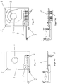
- FIG. 1 shows a top view of the empty lower housing part of the actuator.
- the drive motor In this lower part of the housing is the drive motor, the circuit board, the output shaft (possibly with a grinding spring) and gear wheels that drive the drive shaft of the drive motor couple with the output shaft, inserted removable.
- the upper housing part After the lower housing part like this has been fitted accordingly, the upper housing part is put on and both housing halves releasably connected to one another via a latching connection.
- Drive motor, output shaft and Gear gears are not shown in any of the figures for reasons of clarity.
- the lower part of the housing has a receiving area for the circuit board (3) in the right half.
- the lower housing part has an opening in the form of a cylindrical sleeve (2). This defines the position of the output shaft in the housing.
- the board (3) - see Figure 2 - rests on webs in the lower part of the housing.
- the sleeve (2) engages at least partially in an opening (4) in the circuit board (3) for the passage of the output shaft, so that the circuit board (3) is fixed in its position relative to the output shaft.
- the lower housing part has two positioning pins (1) as positioning means, which engage in corresponding position holes (5) in the circuit board (3).
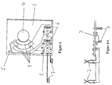
- FIGS. 4 to 5 show three different types of boards.
- All boards (3) have a rectangular base with the same external dimensions, two position holes (5) each arranged at the same locations and a circular opening (4) for the passage of the output shaft and for positioning of the board.
- all the circuit boards (3) have means (6) at a distance from the opening (4) - and thus from the range of rotation of the output shaft - for electrically contacting the drive motor with connection connections arranged outside the housing.
- These means consist of contact sockets (6) soldered into the circuit board, into which plug pins of a plug connector (10) engage, via which the electrical connection is then made to connections located outside the housing.
- the contact sockets (6) for contacting are connected to clamping contacts (7), into which contact lugs on the drive motor engage.
- the clamping contacts (7) are also carried by the circuit board (3). Spaced from the lead-through opening (4) and in the vicinity of the contact sockets, space is provided for electrical (electronic) components, for example for an interference suppression capacitor for the drive motor.
- the board type shown in Figure 4 is the simplest board type. This type of board shows neither resistance slides nor grinding surfaces. He only assigns the for that Modular system standard features on: rectangular base, position holes, Through opening for the abrasion shaft and contact sockets with contact clamps for the Drive motor.
- the type of board shown in FIG. 5 has a concentric to the through opening (4) arranged resistance loop track (8) and a corresponding, likewise concentric to the through opening (4) running grinding surface (9), over which the Loop spring tapped, rotation angle-dependent voltage potential is reported back.
- the board (3) is equipped with three additional contact sockets (6). This board layout allows the detection of the angle of rotation of the output shaft in a certain Angle range.
- the board type shown in FIG. 6 has several concentric to the through opening (4) arranged grinding surfaces (9), which an automatic limit switch of the Enable drive motor in two defined angular positions of the output shaft.
- the connector (10), which acts as an interface between the contact sockets (6) on the board (3) and connection connections outside the housing is preferred can be removed and inserted into the lower part of the housing via slots - see FIGS. 3 and 3A.
- the connector (10) is a modular component in the modular system, because Various embodiments are also provided for the connector, which are: with regard to the geometry of the connector and / or in number and / or Differentiate the arrangement of the connector pins.
Landscapes
- Physics & Mathematics (AREA)
- Thermal Sciences (AREA)
- Engineering & Computer Science (AREA)
- Mechanical Engineering (AREA)
- Motor Or Generator Frames (AREA)
- Connection Of Motors, Electrical Generators, Mechanical Devices, And The Like (AREA)
Abstract
Description
Ein gattungsgemäßer Stellantrieb besteht aus einem zweiteiligen Gehäuse mit einem Gehäuseunterteil und einem Gehäuseoberteil, einem in dem Gehäuse angeordneten elektrischen Antriebsmotor und einer in dem Gehäuse angeordneten Abtriebswelle.
Dabei sind unterschiedliche Funktionstypen von Stellantrieben bekannt. Bei Stellantrieben der einfachsten Art ist weder eine Detektion der Drehwinkelposition der Abtriebswelle noch eine interne Endlagenabschaltung in definierten Drehwinkelpositionen der Abtriebswelle vorgesehen. Daneben gibt es Stellantriebe, bei denen über im Gehäuse angeordnete Widerstandsschleifbahnen in Verbindung mit einer Schleiffeder, welche konzentrisch an der Abtriebswelle angeordnet ist, eine Detektion der Drehwinkelposition der Abtriebswelle möglich ist. Auch hier sind wiederum unterschiedliche Anordnungen und Ausbildungen der Widerstandsschleifbahnen möglich, z.B. hinsichtlich unterschiedlicher Drehwinkelbereiche. Darüber hinaus gibt es Stellantriebe, die über elektrisch leitende Schleifflächen in Verbindung mit der an der Abtriebswelle angeordneten Schleiffeder eine automatische Abschaltung des Antriebsmotors in einer definierten Drehwinkelposition der Abtriebswelle ermöglichen. Auch hier sind wiederum unterschiedliche Anordnungen der Schleifflächen möglich. Ferner sind unterschiedliche Kombinationen von Schleifflächen und Widerstandsschleifbahnen denkbar.
Diese Aufgabe wird erfindungsgemäß dadurch gelöst, dass das Gehäuseunterteil einen Aufnahmebereich und Positioniermittel für eine hinsichtlich der Abtriebswelle positionsgenaue, herausnehmbare Aufnahme von Platinen unterschiedlichen Funktionstyps aufweist. Dabei unterscheiden sich die Platinentypen hinsichtlich des Vorhandenseins, der Anordnung und/oder der Ausbildung von Widerstandsschleifbahnen und/oder von Schleifflächen.
- Figur 1
- eine Draufsicht auf das Gehäuseunterteil des Stellantriebs ohne Platine, Antriebsmotor und Abtriebswelle,
- Figur 2
- eine Draufsicht wie in Figur 1, jedoch mit eingelegter Platine,
- Figur 3
- einen Schnitt durch das Gehäuseunterteil entlang der Linie E-E,
- Figur 3A
- einen Schnitt wie in Figur 3, jedoch vor dem Einsatz des Steckverbinders,
- Figur 4
- einen Draufsicht auf einen ersten Platinentyp,
- Figur 4A
- eine Seitenansicht des ersten Platinentyps,
- Figur 5
- eine Draufsicht auf einen zweiten Platinentyp,
- Figur 5A
- eine Seitenansicht des zweiten Platinentyps,
- Figur 6
- eine Draufsicht auf einen dritten Platinentyp,
- Figur 6A
- eine Seitenansicht des dritten Platinentyps.
In den Figuren 4 bis 5 sind drei verschiedene Platinentypen dargestellt. Alle Platinen (3) weisen eine rechteckige Grundfläche mit denselben Außenabmessungen, zwei jeweils an denselben Stellen angeordnete Positionslöcher (5) sowie eine kreisrunde Öffnung (4) zur Durchführung der Abtriebswelle und zur Positionierung der Platine auf. Außerdem weisen alle Platinen (3) beabstandet von der Öffnung (4) - und damit vom Drehbereich der Abtriebswelle ― Mittel (6) zur elektrischen Kontaktierung des Antriebsmotors mit außerhalb des Gehäuses angeordneten Anschlussverbindungen auf. Diese Mittel bestehen aus in die Platine eingelöteten Kontaktbuchsen (6), in die Steckerstifte eines Steckverbinders (10) eingreifen, über den dann die elektrische Verbindung mit außerhalb des Gehäuses liegenden Anschlüssen erfolgt. Die Kontaktbuchsen (6) für die Kontaktierung sind mit Klemmkontakten (7) verbunden, in die Kontaktfahnen des Antriebsmotors eingreifen. Die Klemmkontakte (7) werden ebenfalls von der Platine (3) getragen. Beabstandet von der Durchführöffnung (4) und in der Nähe der Kontaktbuchsen ist Platz für elektrische (elektronische) Bauelemente vorgesehen, z.B. für einen Entstörkondensator für den Antriebsmotor.
- ohne Detektion des Drehwinkels der Abtriebswelle und ohne automatische Endlagenabschaltung,
- mit Detektion des Drehwinkels der Abtriebswelle und/oder mit automatischer Endlagenabschaltung.
- 1)
- Positionieerstife im Gehäuseunterteil
- 2)
- Zylinderförmige Hülse zur Durchführung und Lagerung der Abtriebswelle im Gehäuseunterteil
- 3)
- Platine
- 4)
- Durchführöffnung in der Platine für die Abtriebswelle
- 5)
- Positionslöcher in der Platine
- 6)
- Kontaktbuchsen auf der Platine
- 7)
- Klemmkontakte für die Kontaktfahnen am Antriebsmotor
- 8)
- Widerstandsschleifbahn
- 9)
- Schleiffläche
- 10)
- Steckverbinder
Claims (8)
- Baukastensystem für einen elektrischen Stellantrieb, insbesondere für Heizungs-, Lüftungs-oder Klimaklappen in einem Kraftfahrzeug bestehend ausdadurch gekennzeichnet, dasseinem zweiteiligen Gehäuse mit einem Gehäuseunterteil und einem Gehäuseoberteil,einem in dem Gehäuse angeordneten elektrischen Antriebsmotor,einer in dem Gehäuse angeordneten Abtriebswelle,
das Gehäuseunterteil einen Aufnahmebereich und Positioniermittel (1, 2) für eine hinsichtlich der Abtriebswelle positionsgenaue, herausnehmbare Aufnahme von Platinen (3) unterschiedlichen Funktionstyps aufweist, wobei die Platinentypen sich hinsichtlich des Vorhandenseins, der Anordnung und/oder der Ausbildung von Widerstandsschleifbahnen (8) und/oder von elektrisch leitenden Schleifflächen (9), welche zur Detektion der Drehwinkelposition der Abtriebswelle und/oder zur Abschaltung des Antriebsmotors in einer definierten Drehwinkelposition der Abtriebswelle dienen, unterscheiden. - Baukastensystem nach Anspruch 1,
dadurch gekennzeichnet, dass
die Platine (3) eine Öffnung (4) zur Durchführung der Abtriebswelle aufweist. - Baukastensystem nach einem der vorstehenden Ansprüche,
dadurch gekennzeichnet, dass
das Gehäuseunterteil eine Hülse (2) zur Durchführung der Abtriebswelle aufweist. - Baukastensystem nach Anspruch 2 und 3,
dadurch gekennzeichnet, dass
die Hülse (2) zumindest teilweise in die Öffnung (4) der Platine (3) eingreift. - Baukastensystem nach Anspruch 1,
dadurch gekennzeichnet, dass
das Gehäuseunterteil zur positionsgenauen Aufnahme der Platine (3) mindestens einen Positionierstift (1) aufweist, der in ein Positionsloch (5) der Platine eingreift oder umgekehrt. - Baukastensystem nach einem der vorstehenden Ansprüche,
dadurch gekennzeichnet, dass
die Platinen (3) in einem Bereich außerhalb des Drehbereichs der Abtriebswelle Mittel (6) zur elektrischen Kontaktierung des Antriebsmotors und/oder der Widerstandsschleifbahn (8) und/oder der Schleiffläche (9) mit einer außerhalb des Gehäuses angeordneten Anschlussverbindung aufweisen. - Baukastensystem nach Anspruch 6,
dadurch gekennzeichnet, dass
in diesem Bereich mindestens ein elektrisches Bauelement angeordnet ist. - Baukastensystem nach einem der vorstehenden Ansprüche,
gekennzeichnet durch
einen in der unteren Gehäusehälfte herausnehmbar einschiebbaren Steckverbinder, über den die Mittel (6) zur elektrischen Kontaktierung des Antriebsmotors und/oder der Widerstandsbahn (8) und/oder der Schleiffläche (9) mit einer außerhalb des Gehäuses angeordneten Anschlussverbindung verbindbar sind.
Applications Claiming Priority (2)
| Application Number | Priority Date | Filing Date | Title |
|---|---|---|---|
| DE10105437A DE10105437A1 (de) | 2001-02-07 | 2001-02-07 | Baukastensystem für einen elektrischen Stellantrieb, insbesondere für Heizungs-, Lüftungs- oder Klimaklappen in einem Kraftfahrzeug |
| DE10105437 | 2001-02-07 |
Publications (2)
| Publication Number | Publication Date |
|---|---|
| EP1231090A2 true EP1231090A2 (de) | 2002-08-14 |
| EP1231090A3 EP1231090A3 (de) | 2003-09-10 |
Family
ID=7673095
Family Applications (1)
| Application Number | Title | Priority Date | Filing Date |
|---|---|---|---|
| EP02002595A Withdrawn EP1231090A3 (de) | 2001-02-07 | 2002-02-05 | Baukastensystem für einen elektrischen Stellantrieb, insbesondere für Heizungs-, Lüftungs- oder Klimaklappen in einem Kraftfahrzeug |
Country Status (2)
| Country | Link |
|---|---|
| EP (1) | EP1231090A3 (de) |
| DE (1) | DE10105437A1 (de) |
Families Citing this family (1)
| Publication number | Priority date | Publication date | Assignee | Title |
|---|---|---|---|---|
| DE102019124151A1 (de) * | 2019-09-09 | 2021-03-11 | Auma Riester Gmbh & Co. Kg | Elektrischer Stellantrieb, elektronisches Baukastensystem und Stellantrieb mit einem DC-Motor |
Family Cites Families (8)
| Publication number | Priority date | Publication date | Assignee | Title |
|---|---|---|---|---|
| US4609794A (en) * | 1985-08-30 | 1986-09-02 | Ford Motor Company | Printed circuit switch for windshield wiper motor |
| US4795867A (en) * | 1986-01-17 | 1989-01-03 | Diesel Kiki Co., Ltd. | Motor actuator for air conditioning system |
| JPS6382811A (ja) * | 1986-09-26 | 1988-04-13 | Nippon Denso Co Ltd | サ−ボモ−タの駆動制御装置 |
| JPH0170609U (de) * | 1987-10-30 | 1989-05-11 | ||
| DE4334124A1 (de) * | 1993-03-04 | 1994-09-08 | Bosch Gmbh Robert | Vorrichtung zum Aufnehmen eines Elektromotors |
| DE4322981C2 (de) * | 1993-07-09 | 1996-02-01 | Hella Kg Hueck & Co | Stellantrieb für die Luftklappe einer Heizungs- oder Klimaanlage für Kraftfahrzeuge |
| DE4415459B4 (de) * | 1994-05-03 | 2006-11-09 | Valeo Climatisation S.A. | Vorrichtung zum Betätigen einer Klappe |
| DE20008200U1 (de) * | 2000-05-06 | 2000-09-28 | Max Stegmann GmbH Antriebstechnik-Elektronik, 78166 Donaueschingen | Baukastensystem zur Fertigung von optischen Drehgebern, sowie entsprechende optische Drehgeber |
-
2001
- 2001-02-07 DE DE10105437A patent/DE10105437A1/de not_active Ceased
-
2002
- 2002-02-05 EP EP02002595A patent/EP1231090A3/de not_active Withdrawn
Non-Patent Citations (1)
| Title |
|---|
| None |
Also Published As
| Publication number | Publication date |
|---|---|
| EP1231090A3 (de) | 2003-09-10 |
| DE10105437A1 (de) | 2003-01-16 |
Similar Documents
| Publication | Publication Date | Title |
|---|---|---|
| EP0952763A2 (de) | Baugruppe mit elektronischen Bauelementen | |
| EP0181534A1 (de) | Einrichtung für ein Kraftfahrzeug | |
| DE10214926A1 (de) | Antriebsvorrichtung | |
| EP2118493A1 (de) | Lüfter mit einem sensor | |
| EP2081796A2 (de) | Steuereinheit zum steuern einer elektromotorischen antriebseinheit | |
| EP3000156B1 (de) | Kontaktvorrichtung zum herstellen eines elektrischen kontaktes zwischen einer leiterplatine und einem elektromotor | |
| EP3175204B1 (de) | Sensoreinrichtung für ein kraftfahrzeug | |
| DE3323472A1 (de) | Entkopplungsanordnung fuer eine auf einer leiterplatte angeordnete integrierte schaltung | |
| EP1282345A2 (de) | Gehäuse zur Aufnahme einer Leiterplatte mit elektronischen Bauteilen in Fahrzeugen | |
| EP0934458B1 (de) | Lastverstelleinrichtung | |
| EP3446368B1 (de) | Steckverbinder für die datenübertragung | |
| EP0402739B1 (de) | Einrichtung zum elektrischen Verbinden von einschiebbaren elektrischen Baugruppen | |
| DE102010034975A1 (de) | Elektronische Schaltung | |
| DE10105437A1 (de) | Baukastensystem für einen elektrischen Stellantrieb, insbesondere für Heizungs-, Lüftungs- oder Klimaklappen in einem Kraftfahrzeug | |
| DE2247273C3 (de) | Magnetspule mit einem Gehäuse und mindestens einer an diesem lösbar befestigbaren Trägerplatte | |
| EP1491077B2 (de) | Steuergerät | |
| DE60201537T2 (de) | Elektrische verbindungsanordnung für elektronische bauteile | |
| DE4445928C2 (de) | Raumtemperaturregler | |
| EP0284915B1 (de) | Elektrische Schalteinheit | |
| DE3337372C2 (de) | ||
| EP3805639B1 (de) | Leuchte mit steckkontakt, verwendung einer solchen leuchte und steckverbinder für eine solche leuchte | |
| DE2823285A1 (de) | Einstellbarer drehwiderstand | |
| EP0982806B1 (de) | Trägerbauteil mit elektrischen Kontaktelementen zum Einbau in einer Leiterplatte | |
| DE29617021U1 (de) | Leiterplatte | |
| EP4429114A1 (de) | Elektronisches elektroinstallationsgerät für die gebäudeinstallation |
Legal Events
| Date | Code | Title | Description |
|---|---|---|---|
| PUAI | Public reference made under article 153(3) epc to a published international application that has entered the european phase |
Free format text: ORIGINAL CODE: 0009012 |
|
| AK | Designated contracting states |
Kind code of ref document: A2 Designated state(s): AT BE CH CY DE DK ES FI FR GB GR IE IT LI LU MC NL PT SE TR |
|
| AX | Request for extension of the european patent |
Free format text: AL;LT;LV;MK;RO;SI |
|
| PUAL | Search report despatched |
Free format text: ORIGINAL CODE: 0009013 |
|
| AK | Designated contracting states |
Kind code of ref document: A3 Designated state(s): AT BE CH CY DE DK ES FI FR GB GR IE IT LI LU MC NL PT SE TR |
|
| AX | Request for extension of the european patent |
Extension state: AL LT LV MK RO SI |
|
| RIC1 | Information provided on ipc code assigned before grant |
Ipc: 7H 02K 5/00 B Ipc: 7B 60H 1/00 A |
|
| 17P | Request for examination filed |
Effective date: 20040205 |
|
| AKX | Designation fees paid |
Designated state(s): DE ES FR GB IT SE |
|
| RAP1 | Party data changed (applicant data changed or rights of an application transferred) |
Owner name: HELLA KGAA HUECK & CO. |
|
| 17Q | First examination report despatched |
Effective date: 20060926 |
|
| STAA | Information on the status of an ep patent application or granted ep patent |
Free format text: STATUS: THE APPLICATION IS DEEMED TO BE WITHDRAWN |
|
| 18D | Application deemed to be withdrawn |
Effective date: 20070901 |