EP1231069A1 - Druckerwagenanordnung mit bewegbarem Druckkopf - Google Patents
Druckerwagenanordnung mit bewegbarem Druckkopf Download PDFInfo
- Publication number
- EP1231069A1 EP1231069A1 EP01303261A EP01303261A EP1231069A1 EP 1231069 A1 EP1231069 A1 EP 1231069A1 EP 01303261 A EP01303261 A EP 01303261A EP 01303261 A EP01303261 A EP 01303261A EP 1231069 A1 EP1231069 A1 EP 1231069A1
- Authority
- EP
- European Patent Office
- Prior art keywords
- bearing
- carriage assembly
- supporting
- guiding rod
- bearing supporting
- Prior art date
- Legal status (The legal status is an assumption and is not a legal conclusion. Google has not performed a legal analysis and makes no representation as to the accuracy of the status listed.)
- Granted
Links
Images


Classifications
-
- B—PERFORMING OPERATIONS; TRANSPORTING
- B41—PRINTING; LINING MACHINES; TYPEWRITERS; STAMPS
- B41J—TYPEWRITERS; SELECTIVE PRINTING MECHANISMS, i.e. MECHANISMS PRINTING OTHERWISE THAN FROM A FORME; CORRECTION OF TYPOGRAPHICAL ERRORS
- B41J2/00—Typewriters or selective printing mechanisms characterised by the printing or marking process for which they are designed
- B41J2/22—Typewriters or selective printing mechanisms characterised by the printing or marking process for which they are designed characterised by selective application of impact or pressure on a printing material or impression-transfer material
- B41J2/23—Typewriters or selective printing mechanisms characterised by the printing or marking process for which they are designed characterised by selective application of impact or pressure on a printing material or impression-transfer material using print wires
- B41J2/235—Print head assemblies
-
- F—MECHANICAL ENGINEERING; LIGHTING; HEATING; WEAPONS; BLASTING
- F16—ENGINEERING ELEMENTS AND UNITS; GENERAL MEASURES FOR PRODUCING AND MAINTAINING EFFECTIVE FUNCTIONING OF MACHINES OR INSTALLATIONS; THERMAL INSULATION IN GENERAL
- F16C—SHAFTS; FLEXIBLE SHAFTS; ELEMENTS OR CRANKSHAFT MECHANISMS; ROTARY BODIES OTHER THAN GEARING ELEMENTS; BEARINGS
- F16C29/00—Bearings for parts moving only linearly
- F16C29/02—Sliding-contact bearings
-
- B—PERFORMING OPERATIONS; TRANSPORTING
- B41—PRINTING; LINING MACHINES; TYPEWRITERS; STAMPS
- B41J—TYPEWRITERS; SELECTIVE PRINTING MECHANISMS, i.e. MECHANISMS PRINTING OTHERWISE THAN FROM A FORME; CORRECTION OF TYPOGRAPHICAL ERRORS
- B41J19/00—Character- or line-spacing mechanisms
-
- B—PERFORMING OPERATIONS; TRANSPORTING
- B41—PRINTING; LINING MACHINES; TYPEWRITERS; STAMPS
- B41J—TYPEWRITERS; SELECTIVE PRINTING MECHANISMS, i.e. MECHANISMS PRINTING OTHERWISE THAN FROM A FORME; CORRECTION OF TYPOGRAPHICAL ERRORS
- B41J25/00—Actions or mechanisms not otherwise provided for
- B41J25/304—Bodily-movable mechanisms for print heads or carriages movable towards or from paper surface
Definitions
- the present invention relates to a printer employing a movable print head, and more particularly, to a carriage assembly of a printer employing a movable print head, which has an improved structure capable of minimizing unstable movement of the carriage, and error in the concentricity of contacting portions of the carriage and a guiding rod.
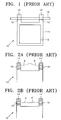
- Figure 1 is a plan view illustrating a conventional carriage assembly for a cartridge having a movable print head.
- a carriage assembly for a cartridge having a movable print head comprises a guiding rod 16, and a carriage 10 which is installed to be movable within a predetermined range along the guiding rod 16, and into which a cartridge having a print head 12 is installed.
- the carriage 10 includes a main body 11 into which the print head 12 is installed, and bosses 14 and 14' extended from the main body 11 and provided with respective shaft holes 15 and 15' so that the guiding rod 16 can be installed to be spaced a predetermined distance from the main body 11 while passing through the shaft holes 15 and 15'.
- the carriage 11 and the guiding rod 16 are required to be made of wearproof materials having a low value of a coefficient of friction between them.
- resin additives of a relatively high price such as a fluoride additive, or the like are used to give high lubricity to a carriage usually formed by injection molding of a synthetic resin, and, actually, the whole body of a carrier is made of a high price material to give high lubricity to portions in which friction occurs.
- Figure 2A is a sectional view illustrating disparity in the central axes of the shaft holes of a conventional carriage assembly
- Figure 2B is a sectional view illustrating error in the scan axes of the shaft holes of a conventional carriage assembly for a movable print head.
- the shaft hole 15 formed at the boss 14 has an axis S
- the shaft hole 15' formed at the boss 14' has an axis S'
- the axes S and S' are not aligned with each other.
- the carriage 10 is made of a metallic material to align the axes of the shaft holes 15 and 15' with each other, it is undesirable that the weight of the carriage 10 which must move side to side repeatedly for printing becomes heavy, and, in addition, the load applied to the guiding rod (not shown) becomes greater. Therefore, the carriage made of a light resin is usually used.
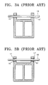
- Figures 3A through 3C Examples of shaft holes provided with a fitting structure are shown in Figures 3A through 3C.
- Figure 3A shows an example in which shaft holes 15 and 15' are formed to be inclined at a predetermined angle while facing each other, and the scan axis of the shaft holes 15 and 15' is aligned with the axis of a guiding rod 16.
- Figure 3B shows an example in which after bushes 17 and 17' are inserted into the respective shaft holes 15 and 15' shown in Figure 3A, the guiding rod 16 is installed to pass through the bushes 17 and 17'.
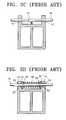
- Figure 3C shows an example in which shaft holes 15 and 15' are formed so that the axes thereof can be parallel to each other, and a spring 18 for supporting a guiding rod 16 is installed so that the scan axis of the shaft holes 15 and 15' can be aligned with the guiding rod 16 .
- FIG. 3D Another example of a fitting structure is shown in Figure 3D.
- the example shown in Figure 3D is disclosed in Korean Utility Model No. 014241 issued Jan. 14, 1999, filed by the applicant of this application.
- hemispherical grooves 31 and 31' are formed at inner sides of respective shaft holes 15 and 15' of bosses 14 and 14', and bearing bushes 33 and 33' having a shape corresponding to the hemispherical grooves 31 and 31' are inserted into the respective hemispherical grooves 31 and 31'.
- Shaft through-holes 34 and 34' through which a guiding rod 16 is inserted are formed through the bearing bushes 33 and 33'.
- a spring 36 is installed between the bearing bushes 33 and 33', and the bearing bushes 33 and 33' are supported by the elastic force of the spring 36 so that the bearing bushes 33 and 33' can be prevented from separated from the shaft holes 15 and 15'.
- a carriage assembly of a printer employing a movable print head, which has an improved structure capable of reducing friction between a carriage and a guiding rod, and aligning the axes of the carriage and the guiding rod with each other.
- the carriage assembly comprising: a plurality of bearing supporting portions provided at a side of the and spaced a predetermined distance from each other, the bearing support portions comprising respective bearing supporting holes each inner circumferential surface of which is formed to have a predetermined radius of curvature; and a plurality of bearing bushes installed in the respective bearing supporting holes of the bearing supporting portions, each outer circumferential surface of which having a different predetermined radius of curvature corresponding to that of the bearing supporting hole so as to make a spherical pair with the corresponding bearing supporting hole, each bearing bush being provided with a shaft through-hole through which the guiding rod can pass slidably.
- a supporting plate having supporting portions pressing the bearing bush for preventing the bearing bush installed in the bearing supporting hole from being separated from the bearing supporting hole is provided fastened to the bearing supporting portion, and an annular projection portion which projects between the supporting portions of the supporting plate is formed to surround the guiding rod.
- the supporting portions of the supporting plate have a predetermined elastic force so as to elastically press the bearing bush.
- the radius of the inner surface of the bearing supporting hole is formed to be greater than the radius of the outer surface of the bearing bush so that the bearing bush can rotate freely in the bearing supporting hole.
- Figure 4 is a perspective view illustrating a carriage assembly for a cartridge having a movable print head according to an embodiment of the present invention
- Figure 5 is an exploded perspective view of the carriage assembly shown in Figure 4
- Figure 6 is a sectional view of the carriage assembly shown in Figure 4.
- a carriage assembly includes a carriage 40 into which a cartridge 41 having a print head is inserted, bearing supporting portions 44 and 44' which are provided at a side of the carriage 40 to be spaced a predetermined distance from each other, and which comprise respective bearing supporting holes 45 and 45', bearing bushes 50 and 50' which are inserted into the bearing supporting holes 45 and 45', respectively, and can rotate freely, and supporting plates 55 and 55' having supporting portions 56 and 56' for pressing the bearing bushes 50 and 50' inserted into the bearing supporting holes 45 and 45' to prevent them from being separated from the bearing supporting holes 45 and 45'.
- the bearing bush 50 is provided with a shaft through-hole 51 so that the guiding rod 60 can pass through the shaft through-hole 51, the outer circumferential surface thereof is formed to have a predetermined radius of curvature.
- the inner circumferential surface of the bearing supporting hole 45 is formed to have a different predetermined radius of curvature corresponding to the radius of curvature of the outer circumferential surface of the bearing bush 50, and the corresponding surfaces of the bearing bush 50 and the bearing supporting hole 45 make a spherical pair.
- annular projecting portion 52 which surrounds the guiding rod 60 so that the bearing bush 50 can be pressed by the supporting portions 56 of the supporting plate 55 is formed at the bearing bush 50.
- the bearing bush 50 is inserted into the bearing supporting hole 45.
- the supporting plate 55 comprises a base 55a, and plate-spring type supporting portions 56 which are extending in parallel from both ends of the base 55a.
- the supporting portions 56 are positioned to surround the annular projecting portion 52, and provide elastic forces so that the bearing bush 50 can be prevented from being separated from the bearing supporting hole 45, and, in addition, the bearing bush 50 through which the guiding rod 60 is inserted can rotate freely in the bearing supporting hole 45, and allow the scan axis of the carriage assembly to be aligned with the axis of the guiding rod 60.
- the supporting portions 56 of the supporting plate 55 have a predetermined elastic force to elastically press the bearing bush 50.
- a screw passing hole 57 for allowing a screw 59 to pass through it is formed through the base 55a of the supporting plate 55 so that the supporting plate 55 can be fastened to the bearing supporting portion 44 by screwing the screw 59 into a threaded hole 46 formed at the bearing supporting portion 44.
- recessed portions 47 having a predetermined depth are formed at an outer circumferential surface 48 of the bearing supporting hole 45 so that the supporting portions 56 can be installed at the bearing supporting portion 44 and press the bearing bush 50. Therefore, the supporting portions 56 of the supporting plate 55 are installed in the recessed portions 47 to surround the annular projecting portion 52of the bearing bush 50.
- Figure 7 is an enlarged sectional view of the portion A shown in Figure 6.
- the inner radius R of the bearing supporting hole 45 is formed to be greater than the outer radius r of the bearing bush 50 so that the bearing supporting hole 45 can be spaced a predetermined distance from the bearing bush 50. This is intended to allow the bearing bush 50 to freely rotate with respect to the bearing supporting hole 45 so that the scan axis of the carriage assembly can be aligned with the axis of the guiding rod 60.
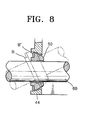
- Figure 8 is a diagram illustrating a mechanism allowing a bearing bush to freely rotate in a bearing supporting hole so that the scan axis of a carriage assembly can be aligned with the axis of a guiding rod.
- the carriage 40 is moved along the guiding rod 60 by a drive system (not shown).
- the bearing bush 50 through which the guiding rod 60 is inserted can rotate in the bearing supporting hole 45. Therefore, even when the bearing supporting hole 45 is erroneously machined to some extent, the scan axis of the carriage assembly 40 can be aligned with the axis of the guiding rod 60.
- the bearing supporting holes 45 and 45' are erroneously machined to receive the respective bearing bushes 50 and 50' correctly, since the bearing bushes 50 and 50' has a predetermined radius of curvature corresponding to that of the bearing supporting holes 45 and 45', and the bearing bushes 50 and 50' can rotate freely from a state B shown in dotted lines to a state B' shown in solid lines, the scan axis of the carriage assembly can be aligned with the axis of the guiding rod 60.
- the carriage assembly of a printer having a structure as described above has a simple structure and the manufacturing cost thereof is low.
- unsteady movement of the carriage can be lowered, and the scan axis of the carriage assembly can be aligned with the axis of the guiding rod automatically, error in the axes of the carriage assembly and the guiding rod can be lowered markedly.
- the bearing bushes having a predetermined radius of curvature can rotate freely in the respective bearing supporting holes having a different but corresponding radius of curvature, and the scan axis of the carriage assembly can be aligned with the axis of the guiding rod automatically even when the bearing supporting holes are erroneously machined, the manufacturing cost of the carriage assembly according to the present invention is low, and unsteady movement of the carriage assembly can be lowered markedly.
Landscapes
- Engineering & Computer Science (AREA)
- General Engineering & Computer Science (AREA)
- Mechanical Engineering (AREA)
- Character Spaces And Line Spaces In Printers (AREA)
- Support Of The Bearing (AREA)
- Accessory Devices And Overall Control Thereof (AREA)
Applications Claiming Priority (2)
| Application Number | Priority Date | Filing Date | Title |
|---|---|---|---|
| KR2001006980 | 2001-02-13 | ||
| KR10-2001-0006980A KR100385992B1 (ko) | 2001-02-13 | 2001-02-13 | 왕복식 프린터헤드의 캐리지 어셈블리 |
Publications (2)
| Publication Number | Publication Date |
|---|---|
| EP1231069A1 true EP1231069A1 (de) | 2002-08-14 |
| EP1231069B1 EP1231069B1 (de) | 2006-10-18 |
Family
ID=19705675
Family Applications (1)
| Application Number | Title | Priority Date | Filing Date |
|---|---|---|---|
| EP01303261A Expired - Lifetime EP1231069B1 (de) | 2001-02-13 | 2001-04-06 | Druckerwagenanordnung mit bewegbarem Druckkopf |
Country Status (6)
| Country | Link |
|---|---|
| US (1) | US6666599B2 (de) |
| EP (1) | EP1231069B1 (de) |
| JP (1) | JP3620793B2 (de) |
| KR (1) | KR100385992B1 (de) |
| CN (1) | CN1162278C (de) |
| DE (1) | DE60123918T2 (de) |
Cited By (1)
| Publication number | Priority date | Publication date | Assignee | Title |
|---|---|---|---|---|
| EP2942199A1 (de) * | 2014-05-07 | 2015-11-11 | Canon Kabushiki Kaisha | Gestell und aufzeichnungsvorrichtung und verfahren zur herstellung des gestells |
Families Citing this family (6)
| Publication number | Priority date | Publication date | Assignee | Title |
|---|---|---|---|---|
| US7410317B2 (en) * | 2003-08-26 | 2008-08-12 | Oki Data Corporation | Method for processing medium, image processing apparatus, and printer apparatus |
| US7128391B2 (en) * | 2004-06-30 | 2006-10-31 | Lexmark International, Inc. | Self aligning printhead carrier bearings for an imaging apparatus |
| JP5170373B2 (ja) * | 2007-07-17 | 2013-03-27 | セイコーエプソン株式会社 | 動力伝達切換装置および記録装置 |
| KR101924239B1 (ko) * | 2010-10-15 | 2018-11-30 | 멤젯 테크놀로지 엘티디 | 복수의 단색 인쇄 카트리지 인쇄장치 및 인쇄 정렬 방법 |
| CN103373069B (zh) * | 2012-04-13 | 2015-10-21 | 株式会社理光 | 图像形成装置 |
| US10514061B2 (en) * | 2018-05-23 | 2019-12-24 | John Wun-Chang Shih | Linear moving bearing |
Citations (2)
| Publication number | Priority date | Publication date | Assignee | Title |
|---|---|---|---|---|
| US5332321A (en) * | 1992-10-23 | 1994-07-26 | Hewlett-Packard Corporation | Two line contact bushing mounting of a plotter carriage with pre-load |
| EP1013457A1 (de) * | 1998-10-29 | 2000-06-28 | Hewlett-Packard Company | Druckerschlittenbuchse |
Family Cites Families (2)
| Publication number | Priority date | Publication date | Assignee | Title |
|---|---|---|---|---|
| US5887994A (en) * | 1989-10-20 | 1999-03-30 | Canon Kabushiki Kaisha | Bearing mechanism and ink jet recording apparatus having same |
| US6340221B1 (en) * | 2000-09-18 | 2002-01-22 | Hewlett-Packard Company | Ink jet print carriage drive system that applies drive force at location displaced from drive belt |
-
2001
- 2001-02-13 KR KR10-2001-0006980A patent/KR100385992B1/ko not_active Expired - Fee Related
- 2001-04-06 DE DE60123918T patent/DE60123918T2/de not_active Expired - Lifetime
- 2001-04-06 EP EP01303261A patent/EP1231069B1/de not_active Expired - Lifetime
- 2001-04-25 CN CNB011170999A patent/CN1162278C/zh not_active Expired - Fee Related
- 2001-07-02 US US09/896,113 patent/US6666599B2/en not_active Expired - Lifetime
- 2001-08-22 JP JP2001251608A patent/JP3620793B2/ja not_active Expired - Fee Related
Patent Citations (2)
| Publication number | Priority date | Publication date | Assignee | Title |
|---|---|---|---|---|
| US5332321A (en) * | 1992-10-23 | 1994-07-26 | Hewlett-Packard Corporation | Two line contact bushing mounting of a plotter carriage with pre-load |
| EP1013457A1 (de) * | 1998-10-29 | 2000-06-28 | Hewlett-Packard Company | Druckerschlittenbuchse |
Cited By (2)
| Publication number | Priority date | Publication date | Assignee | Title |
|---|---|---|---|---|
| EP2942199A1 (de) * | 2014-05-07 | 2015-11-11 | Canon Kabushiki Kaisha | Gestell und aufzeichnungsvorrichtung und verfahren zur herstellung des gestells |
| US9533511B2 (en) | 2014-05-07 | 2017-01-03 | Canon Kabushiki Kaisha | Carriage and recording apparatus and method for manufacturing the carriage |
Also Published As
| Publication number | Publication date |
|---|---|
| DE60123918T2 (de) | 2007-04-19 |
| EP1231069B1 (de) | 2006-10-18 |
| JP3620793B2 (ja) | 2005-02-16 |
| US6666599B2 (en) | 2003-12-23 |
| CN1370685A (zh) | 2002-09-25 |
| KR20020066665A (ko) | 2002-08-21 |
| DE60123918D1 (de) | 2006-11-30 |
| JP2002248828A (ja) | 2002-09-03 |
| US20020110398A1 (en) | 2002-08-15 |
| KR100385992B1 (ko) | 2003-06-02 |
| CN1162278C (zh) | 2004-08-18 |
Similar Documents
| Publication | Publication Date | Title |
|---|---|---|
| CN113043906B (zh) | 一种换电式纯电动重卡换电系统结构 | |
| EP1231069A1 (de) | Druckerwagenanordnung mit bewegbarem Druckkopf | |
| US8870002B2 (en) | Railroad freight car draft gear assembly | |
| KR20090114402A (ko) | 스러스트 슬라이딩 베어링 및 이 스러스트 슬라이딩 베어링과 피스톤 로드의 조합 기구 | |
| US20050116402A1 (en) | Polymer and rigid suspension bearing assembly for motor vehicles | |
| US5622434A (en) | Linear bearing structure | |
| EP1013457B1 (de) | Druckerschlittenbuchse | |
| US4461518A (en) | Sliding roller bearing | |
| EP1750878A1 (de) | Reibkupplung, reibanordnung und eine reibkupplung umfassender pressentisch sowie verfahren | |
| CN111075911A (zh) | 用于轴向间隙补偿的补偿组件和传动单元 | |
| EP0723632B1 (de) | Kranausleger mit führungsscheibe | |
| JPS6144540Y2 (de) | ||
| JPH09166137A (ja) | 平行2軸スライダ構造 | |
| CN210435937U (zh) | 缸体珩磨机 | |
| CN218671383U (zh) | 手动调角装置 | |
| CN221248551U (zh) | 一种紧凑型重载滑块组件 | |
| KR20190065393A (ko) | 미끄럼 베어링 | |
| CN222791934U (zh) | 一种浮动安装机构及压套设备 | |
| JPH0540488Y2 (de) | ||
| CN218140927U (zh) | 一种可准确连接的底座 | |
| CN220073807U (zh) | 浮动连接结构及机壳定位工装 | |
| CN222910549U (zh) | 自调心直线轴承 | |
| CN216904617U (zh) | 装配工装 | |
| CN212564000U (zh) | 一种轴用挡圈 | |
| JPH0230296Y2 (de) |
Legal Events
| Date | Code | Title | Description |
|---|---|---|---|
| PUAI | Public reference made under article 153(3) epc to a published international application that has entered the european phase |
Free format text: ORIGINAL CODE: 0009012 |
|
| 17P | Request for examination filed |
Effective date: 20010411 |
|
| AK | Designated contracting states |
Kind code of ref document: A1 Designated state(s): AT BE CH CY DE DK ES FI FR GB GR IE IT LI LU MC NL PT SE TR |
|
| AX | Request for extension of the european patent |
Free format text: AL;LT;LV;MK;RO;SI |
|
| AKX | Designation fees paid |
Designated state(s): DE FR GB IT |
|
| 17Q | First examination report despatched |
Effective date: 20041116 |
|
| GRAP | Despatch of communication of intention to grant a patent |
Free format text: ORIGINAL CODE: EPIDOSNIGR1 |
|
| GRAS | Grant fee paid |
Free format text: ORIGINAL CODE: EPIDOSNIGR3 |
|
| GRAA | (expected) grant |
Free format text: ORIGINAL CODE: 0009210 |
|
| AK | Designated contracting states |
Kind code of ref document: B1 Designated state(s): DE FR GB IT |
|
| PG25 | Lapsed in a contracting state [announced via postgrant information from national office to epo] |
Ref country code: IT Free format text: LAPSE BECAUSE OF FAILURE TO SUBMIT A TRANSLATION OF THE DESCRIPTION OR TO PAY THE FEE WITHIN THE PRESCRIBED TIME-LIMIT;WARNING: LAPSES OF ITALIAN PATENTS WITH EFFECTIVE DATE BEFORE 2007 MAY HAVE OCCURRED AT ANY TIME BEFORE 2007. THE CORRECT EFFECTIVE DATE MAY BE DIFFERENT FROM THE ONE RECORDED. Effective date: 20061018 |
|
| REG | Reference to a national code |
Ref country code: GB Ref legal event code: FG4D |
|
| REF | Corresponds to: |
Ref document number: 60123918 Country of ref document: DE Date of ref document: 20061130 Kind code of ref document: P |
|
| EN | Fr: translation not filed | ||
| PLBE | No opposition filed within time limit |
Free format text: ORIGINAL CODE: 0009261 |
|
| STAA | Information on the status of an ep patent application or granted ep patent |
Free format text: STATUS: NO OPPOSITION FILED WITHIN TIME LIMIT |
|
| 26N | No opposition filed |
Effective date: 20070719 |
|
| PG25 | Lapsed in a contracting state [announced via postgrant information from national office to epo] |
Ref country code: FR Free format text: LAPSE BECAUSE OF FAILURE TO SUBMIT A TRANSLATION OF THE DESCRIPTION OR TO PAY THE FEE WITHIN THE PRESCRIBED TIME-LIMIT Effective date: 20070601 |
|
| PG25 | Lapsed in a contracting state [announced via postgrant information from national office to epo] |
Ref country code: FR Free format text: LAPSE BECAUSE OF FAILURE TO SUBMIT A TRANSLATION OF THE DESCRIPTION OR TO PAY THE FEE WITHIN THE PRESCRIBED TIME-LIMIT Effective date: 20061018 |
|
| REG | Reference to a national code |
Ref country code: GB Ref legal event code: 732E Free format text: REGISTERED BETWEEN 20170406 AND 20170412 |
|
| REG | Reference to a national code |
Ref country code: DE Ref legal event code: R082 Ref document number: 60123918 Country of ref document: DE Representative=s name: GRUENECKER PATENT- UND RECHTSANWAELTE PARTG MB, DE Ref country code: DE Ref legal event code: R081 Ref document number: 60123918 Country of ref document: DE Owner name: HP PRINTING KOREA CO., LTD., SUWON-SI, KR Free format text: FORMER OWNER: SAMSUNG ELECTRONICS CO., LTD., SUWON-SI, GYEONGGI-DO, KR Ref country code: DE Ref legal event code: R081 Ref document number: 60123918 Country of ref document: DE Owner name: HEWLETT-PACKARD DEVELOPMENT COMPANY, L.P., SPR, US Free format text: FORMER OWNER: SAMSUNG ELECTRONICS CO., LTD., SUWON-SI, GYEONGGI-DO, KR Ref country code: DE Ref legal event code: R081 Ref document number: 60123918 Country of ref document: DE Owner name: S-PRINTING SOLUTION CO., LTD., SUWON-SI, KR Free format text: FORMER OWNER: SAMSUNG ELECTRONICS CO., LTD., SUWON-SI, GYEONGGI-DO, KR |
|
| REG | Reference to a national code |
Ref country code: DE Ref legal event code: R082 Ref document number: 60123918 Country of ref document: DE Ref country code: DE Ref legal event code: R081 Ref document number: 60123918 Country of ref document: DE Owner name: HP PRINTING KOREA CO., LTD., SUWON-SI, KR Free format text: FORMER OWNER: S-PRINTING SOLUTION CO., LTD., SUWON-SI, GYEONGGI-DO, KR Ref country code: DE Ref legal event code: R081 Ref document number: 60123918 Country of ref document: DE Owner name: HEWLETT-PACKARD DEVELOPMENT COMPANY, L.P., SPR, US Free format text: FORMER OWNER: S-PRINTING SOLUTION CO., LTD., SUWON-SI, GYEONGGI-DO, KR |
|
| PGFP | Annual fee paid to national office [announced via postgrant information from national office to epo] |
Ref country code: GB Payment date: 20190325 Year of fee payment: 19 |
|
| PGFP | Annual fee paid to national office [announced via postgrant information from national office to epo] |
Ref country code: DE Payment date: 20190220 Year of fee payment: 19 |
|
| REG | Reference to a national code |
Ref country code: DE Ref legal event code: R081 Ref document number: 60123918 Country of ref document: DE Owner name: HEWLETT-PACKARD DEVELOPMENT COMPANY, L.P., SPR, US Free format text: FORMER OWNER: HP PRINTING KOREA CO., LTD., SUWON-SI, GYEONGGI-DO, KR |
|
| REG | Reference to a national code |
Ref country code: GB Ref legal event code: 732E Free format text: REGISTERED BETWEEN 20191212 AND 20191218 |
|
| REG | Reference to a national code |
Ref country code: DE Ref legal event code: R119 Ref document number: 60123918 Country of ref document: DE |
|
| PG25 | Lapsed in a contracting state [announced via postgrant information from national office to epo] |
Ref country code: DE Free format text: LAPSE BECAUSE OF NON-PAYMENT OF DUE FEES Effective date: 20201103 |
|
| GBPC | Gb: european patent ceased through non-payment of renewal fee |
Effective date: 20200406 |
|
| PG25 | Lapsed in a contracting state [announced via postgrant information from national office to epo] |
Ref country code: GB Free format text: LAPSE BECAUSE OF NON-PAYMENT OF DUE FEES Effective date: 20200406 |