EP1229675A2 - Pumplichtquelle für Ramanverstärker und Ramanverstärker der diese verwendet - Google Patents
Pumplichtquelle für Ramanverstärker und Ramanverstärker der diese verwendet Download PDFInfo
- Publication number
- EP1229675A2 EP1229675A2 EP02250710A EP02250710A EP1229675A2 EP 1229675 A2 EP1229675 A2 EP 1229675A2 EP 02250710 A EP02250710 A EP 02250710A EP 02250710 A EP02250710 A EP 02250710A EP 1229675 A2 EP1229675 A2 EP 1229675A2
- Authority
- EP
- European Patent Office
- Prior art keywords
- light source
- light
- lightwaves
- pump
- raman amplification
- Prior art date
- Legal status (The legal status is an assumption and is not a legal conclusion. Google has not performed a legal analysis and makes no representation as to the accuracy of the status listed.)
- Withdrawn
Links
Images


Classifications
-
- H—ELECTRICITY
- H04—ELECTRIC COMMUNICATION TECHNIQUE
- H04B—TRANSMISSION
- H04B10/00—Transmission systems employing electromagnetic waves other than radio-waves, e.g. infrared, visible or ultraviolet light, or employing corpuscular radiation, e.g. quantum communication
- H04B10/29—Repeaters
- H04B10/291—Repeaters in which processing or amplification is carried out without conversion of the main signal from optical form
- H04B10/2912—Repeaters in which processing or amplification is carried out without conversion of the main signal from optical form characterised by the medium used for amplification or processing
- H04B10/2916—Repeaters in which processing or amplification is carried out without conversion of the main signal from optical form characterised by the medium used for amplification or processing using Raman or Brillouin amplifiers
Definitions
- the present invention relates to a pump light source for a Raman amplifier for optically amplifying signal lightwaves in a light transmission path such as an optical fiber by utilizing stimulated Raman scattering and to a Raman amplifier using the same.
- an optical amplifier 5 when guiding an optical signal 2 output from a light transmitting station 1 to a light receiving station 4 through a light transmission path 3, such as an optical fiber, an optical amplifier 5 is arranged at some midpoint in the light transmission path 3 or at an end thereof to optically amplify the optical signal so that the optical signal 2, which has been attenuated in the light transmission path 3, may attain the requisite optical signal level for reception by the light receiving station 4.
- the optical amplifier 5 is provided at the forward end or both ends of the light transmission path 3.
- electrical information to be transmitted is converted into light to be output to the light transmission path 3.
- An electric signal is converted to an optical signal by applying it directly to a semiconductor laser diode or the like serving as the signal light source or by modulating the light oscillated from the signal light source by an external modulator provided behind the signal light source before it is output to the light transmission path 3.
- the optical signal 2 propagated through the light transmission path 3 is converted into an electric signal by a photoelectric converter, such as a photo diode, and the information transmitted from the light transmitting station 1 is demodulated, whereby the information is read.
- a photoelectric converter such as a photo diode
- oscillation light from a pump light source 7 is input to a Raman amplification medium 31 through an optical coupler 6 from an end portion of the Raman amplification medium 31 constituting a part of the light transmission path 3 to cause Raman scattering in the Raman amplification medium 31, thereby effecting Raman amplification on the optical signal 2.
- the wavelength of the oscillation light to be selected is shorter than the wavelength of the optical signal 2 from the light transmitting station 1 by approximately 20 to 200 nm.
- the Raman gain due to the Raman amplification in the Raman amplification medium 31 allows light amplification over a wide range. However, it does not allow uniform amplification over a wide signal band, exhibiting wavelength properties in amplification gain. Thus, to effect uniform Raman amplification over a wide signal band, a plurality of pump light sources of different wavelengths from each other are used in order to adjust the intensity of the pump lightwaves such that Raman gain is uniform over the signal band.
- the above method in which the intensity of oscillation light of a plurality of light sources is adjusted has a problem in that the gain of a specific signal band is not adjusted by adjusting one of the plurality of light sources; it involves a change in the gain of a still wider signal band including the specific signal band, so that it is not easy to adjust the gain to a desired value.
- the present inventor performed signal band gain measurement with the pump intensity of the semiconductor LD of 1460.265 nm reduced to 80%, 60%, 40%, and 20%, as shown in (10) through (13) of Table 2.
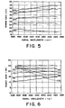
- the results are the values indicated by the dotted lines (10) through (13) of Fig. 6. In these dotted lines, the gain at the shorter wavelength of the signal band does not vary compared with the gain at the longer wavelength, and the gain flatness is sufficient.
- the present inventor divided pumps optimized so as to obtain flat gain properties in a certain signal band into Group A of the shorter wavelength and Group B of the longer wavelength to find out the following:
- pump wavelengths are divided into two groups; the shorter wavelengths and the longer wavelengths, which are arbitrarily adjusted, whereby it is possible to obtain arbitrary gain properties.
- a pump light source for outputting a plurality of pump lightwaves for effecting Raman amplification on signal lightwaves input to a light transmission path
- the pump light source for Raman amplification is divided into light source whose oscillation wavelengths are the shorter (hereinafter referred to as “shorter wavelength light source) and light source whose oscillation wavelengths are the longer (hereinafter referred to as "longer wavelength light source); a plurality of lightwaves emitted from the shorter wavelength light source and a lightwave emitted from the longer wavelength light source are coupled and output; and the plurality of lightwaves output from the shorter wavelength light source or the lightwave output from the longer wavelength light source is collectively controlled to adjust the intensity of the output light.
- a Raman amplifier including a light transmitting station for emitting signal lightwaves, a light receiving station for receiving the signal lightwaves, a light transmission path for propagating the signal lightwaves from the light transmitting station to the light receiving station, and a pump light source for Raman amplification which introduces pump lightwaves into the light transmission path to cause Raman scattering in the light transmission path to thereby effect Raman amplification on the signal lightwaves, wherein the pump light source for Raman amplification is as claimed in one of Claims 1 through 5.
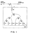
- Fig. 1 is a schematic diagram showing an embodiment of the present invention.
- 31, 6, and 7 respectively indicate a Raman amplification medium, such as a silica-based optical fiber, an optical coupler for coupling pump lightwaves with signal lightwaves to be integrated in the Raman amplification medium, and a Raman amplification pump light source.
- 71 ⁇ 71 indicate semiconductor laser diodes of an oscillation wavelength of 1423.516 nm
- 72 indicates a semiconductor laser diode of an oscillation wavelength of 1430.990 nm
- 73 indicates a semiconductor laser diode of an oscillation wavelength of 1438.543 nm
- 74 ⁇ 74 indicate semiconductor laser diodes of an oscillation wavelength of 1460.265 nm.
- 75 and 76 indicate polarization beam combiner
- 77, 78, and 79 indicate wavelength optical multiplexers for coupling two lightwaves
- 80 indicates an optical isolator.
- 81 indicates a current controller capable of supplying drive current to the semiconductor laser diodes 71 through 74 and controlling the current values thereof.
- the lightwaves from the semiconductor laser diodes 71 ⁇ 71 are coupled in the polarization beam combiner 75 such that their states of polarization differ from each other by 90 degrees, and then output.
- the lightwaves from the semiconductor laser diodes 74 ⁇ 74 are coupled in the polarization beam combiner 76 such that their states of polarization differ from each other by 90 degrees, and then output.
- the lightwaves from the semiconductor laser diodes 71 ⁇ 71, coupled by the polarization beam combiner 75, and the lightwave from the semiconductor laser diode 72 are coupled by the wavelength optical multiplexer 77.
- the lightwaves from the semiconductor laser diodes 74 ⁇ 74, coupled by the polarization beam combiner 76, and the lightwave from the semiconductor laser diode 73 are coupled by the wavelength optical multiplexer 78.
- the lightwaves output from the wavelength optical multiplexers 77 and 78 are coupled by the wavelength optical multiplexer 79, and guided to the Raman amplification medium 31 through the optical coupler 6 and the isolator 80.
- Forty-four input signals in substantially uniform variation between wavelengths of 1527.994 nm and 1562.233 nm are introduced into the Raman amplification medium 31 from the input end in a magnitude of substantially -15 dBm/ch.
- the semiconductor laser diodes 71 ⁇ 71 are adjusted by the current controller 81 such that optical powers of them are the same each other.
- the semiconductor laser diodes 74 ⁇ 74 are adjusted by the current controller 81 such that optical powers of them are the same each other.
- the drive current for the semiconductor laser diodes 71 through 74 was adjusted by the current controller 81, an optical spectrum analyzer (not shown) was mounted to the output end, and current adjustment was performed such that the gain was approximately 25 dB and flat over the entire signal band.
- the light intensities of the semiconductor laser diodes 71 through 74 at this time were respectively 248 mW, 170 mW, 128 mW, and 264.5 mW as shown in (1) of Table 4, (The intensity of light output from each of the semiconductor laser diodes 71 and 74 is 1/2 thereof).
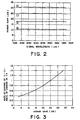
- the gain is within the range of 24.74 to 25.30 dB, and is in a substantially flat state as shown in (1) of Fig. 2.
- this value will be defined as pump power 100% for the sake of convenience.
- Shorter wavelength group Longer wavelength group ⁇ 1 ⁇ 2 ⁇ 3 ⁇ 4 (1) 100% 100% 248.0 170.0 128.0 264.50 (2) 140% 113% 348.60 238.00 179.20 343.85 (3) 60% 84% 149.40 102.00 76.80 211.60 (4) 31.2% 60% 77.688 53.040 39.936 158.700 [mW]
- the light intensity of the semiconductor laser diodes 71 through 73 was increased to 140%, and the light intensity of the semiconductor laser diode 74 was increased to 113%, as shown in (2) of Table 4.
- the respective light intensities of the semiconductor laser diodes 71 through 74 at that time were 348.6 mW, 238 mW, 179.2 mW, and 343.85 mW (The light intensity of the light output from each of the semiconductor laser diodes 71 and 74 is 1/2 thereof).
- the gain at this time is within the range of 30.01 to 30.77 dB, and is in a substantially flat state as shown in (2) of Fig. 2.
- the light intensity of the semiconductor laser diodes 71 through 73 was reduced to 60%, and the light intensity of the semiconductor laser diode 74 was reduced to 84%, as shown in (3) of Table 4.
- the respective light intensities of the semiconductor laser diodes 71 through 74 at that time were 149.4 mW, 102 mW, 76.8 mW, and 211.6 mW (The intensity of the light output from each of the semiconductor laser diodes 71 and 74 is 1/2 thereof).
- the gain at this time is within the range of 17.36 to 17.76 dB, and is in a substantially flat state, as shown in (3) of Fig. 2.
- the light intensity of the semiconductor laser diodes 71 through 73 was reduced to 31.2%, and the light intensity of the semiconductor laser diode 74 was reduced to 60%, as shown in (4) of Table 4.
- the respective light intensities of the semiconductor laser diodes 71 through 74 at that time were 77.688 mW, 53.04 mW, 39.936 mW, and 158.7 mW (The intensity of the light output from each of the semiconductor laser diodes 71 and 74 is 1/2 thereof).
- the gain at this time is within the range of 10.44 to 10.73 dB, and is in a substantially flat state, as shown in Fig. 2, (4).
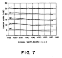
- the drive current at the shorter wavelength group and the drive current at the longer wavelength group were collectively controlled to further vary the intensity of the light from each semiconductor laser diode in a manner other than that of the above-mentioned four examples so as to obtain a substantially flat gain over the entire signal wavelength band.
- Table 5 shows the percentage of the pump power, using the above-mentioned 100% as a reference.
- Fig. 3 is a graph plotting the measurement values.
- the vertical axis (Y-axis) indicates the rate of change of the semiconductor laser diodes 71 through 73 with respect to the rate of change of the semiconductor laser diode 74, and the horizontal axis (X-axis) indicates the gain properties.
- ⁇ is substituted in the X of the above equation to obtain the value of Y, and solely by adjusting the light intensities of both wavelength groups while setting the ratio of the light intensity of the shorter wavelength group to the light intensity of the longer wavelength group such that it becomes equal to the above value of Y, it is possible to obtain an arbitrary flat gain property.
- Fig. 4 is a schematic diagram showing another embodiment of the present invention.
- 82 and 83 indicate optical attenuators
- 84 indicates a controller for controlling the attenuation amount thereof.
- the other components are the same as those of Fig. 1.
- the lightwaves from the semiconductor laser diodes 71 ⁇ 71 are coupled in the polarization beam combiner 75 such that their states of polarization differ from each other by 90 degrees before being output.
- the lightwaves from the semiconductor laser diodes 74 ⁇ 74 are coupled in the polarization beam combiner 76 such that their states of polarization differ from each other by 90 degrees before being output.
- the lightwaves from the semiconductor laser diodes 71 ⁇ 71, coupled by the polarization beam combiner 75, and the lightwave from the semiconductor laser diode 72 are coupled by the wavelength optical multiplexer 77.
- the lightwaves from the semiconductor laser diodes 71 ⁇ 71 and 72, coupled by the wavelength optical multiplexer 77, and the lightwave from the semiconductor laser diode 73 are coupled by the wavelength optical multiplexer 78.
- the lightwaves output from the wavelength optical multiplexer 78 and the polarization beam combiner 76 are attenuated by the optical attenuators 82 and 83, respectively and then coupled by the wavelength optical multiplexer 79 before being guided to the optical coupler 6 through the isolator 80 and then guided to the Raman amplification medium 31.
- the cases are explained where there are three light sources at the shorter wavelength group and one light source at the longer wavelength group.
- the present invention may be also applied to other cases where the number of light sources for each group is not the number disclosed above. However, it is always necessary to provide a plurality of light sources for the shorter wavelength group. Needless to say, the light source for each group may include one or more wavelengths.
Landscapes
- Physics & Mathematics (AREA)
- Electromagnetism (AREA)
- Engineering & Computer Science (AREA)
- Computer Networks & Wireless Communication (AREA)
- Signal Processing (AREA)
- Optical Modulation, Optical Deflection, Nonlinear Optics, Optical Demodulation, Optical Logic Elements (AREA)
- Lasers (AREA)
Applications Claiming Priority (2)
| Application Number | Priority Date | Filing Date | Title |
|---|---|---|---|
| JP2001027201 | 2001-02-02 | ||
| JP2001027201 | 2001-02-02 |
Publications (2)
| Publication Number | Publication Date |
|---|---|
| EP1229675A2 true EP1229675A2 (de) | 2002-08-07 |
| EP1229675A3 EP1229675A3 (de) | 2004-09-22 |
Family
ID=18891901
Family Applications (1)
| Application Number | Title | Priority Date | Filing Date |
|---|---|---|---|
| EP02250710A Withdrawn EP1229675A3 (de) | 2001-02-02 | 2002-02-01 | Pumplichtquelle für Ramanverstärker und Ramanverstärker der diese verwendet |
Country Status (3)
| Country | Link |
|---|---|
| US (1) | US6950230B2 (de) |
| EP (1) | EP1229675A3 (de) |
| CA (1) | CA2369766A1 (de) |
Families Citing this family (5)
| Publication number | Priority date | Publication date | Assignee | Title |
|---|---|---|---|---|
| KR100533914B1 (ko) * | 2003-10-08 | 2005-12-06 | 한국전자통신연구원 | 라만 증폭기 및 라만 펌핑 방법 |
| EP1788728A1 (de) * | 2005-11-18 | 2007-05-23 | Alcatel Lucent | Ramanverstärker und optisches Übertragungssystem |
| JP4750688B2 (ja) * | 2006-12-27 | 2011-08-17 | 富士通株式会社 | ラマン増幅器 |
| JP5058855B2 (ja) * | 2008-03-13 | 2012-10-24 | キヤノン株式会社 | 情報処理装置およびその方法並びにプログラム |
| US9017334B2 (en) | 2009-02-24 | 2015-04-28 | Microport Orthopedics Holdings Inc. | Patient specific surgical guide locator and mount |
Family Cites Families (28)
| Publication number | Priority date | Publication date | Assignee | Title |
|---|---|---|---|---|
| US4616898A (en) * | 1980-03-31 | 1986-10-14 | Polaroid Corporation | Optical communication systems using raman repeaters and components therefor |
| JPS56165437A (en) * | 1980-05-26 | 1981-12-19 | Kokusai Denshin Denwa Co Ltd <Kdd> | Optical repeating system for optical communication |
| US4699452A (en) * | 1985-10-28 | 1987-10-13 | American Telephone And Telegraph Company, At&T Bell Laboratories | Optical communications system comprising Raman amplification means |
| US6191877B1 (en) * | 1995-02-17 | 2001-02-20 | Lucent Technologies Inc. | WDM optical fiber system using Raman amplification |
| US5673280A (en) * | 1996-02-12 | 1997-09-30 | Lucent Technologies Inc. | Article comprising low noise optical fiber raman amplifier |
| US5959750A (en) * | 1996-06-06 | 1999-09-28 | Lucent Technologies Inc. | Method of upgrading transmission capacity by Raman amplification |
| US5946428A (en) * | 1996-07-09 | 1999-08-31 | Corning Incorporated | Fiber optic system with simultaneous switching and raman |
| US5966206A (en) * | 1996-10-10 | 1999-10-12 | Tyco Submarine Systems Ltd. | Interlocked high power fiber system using OTDR |
| US6212310B1 (en) * | 1996-10-22 | 2001-04-03 | Sdl, Inc. | High power fiber gain media system achieved through power scaling via multiplexing |
| US6081323A (en) * | 1997-02-27 | 2000-06-27 | The United States Of America As Represented By The Director Of The National Security Agency | Measurement of Raman gain spectrum in optical fiber |
| US6081366A (en) * | 1997-08-28 | 2000-06-27 | Lucent Technologies Inc. | Optical fiber communication system with a distributed Raman amplifier and a remotely pumped er-doped fiber amplifier |
| US5887093A (en) * | 1997-09-12 | 1999-03-23 | Lucent Technologies Incorporated | Optical fiber dispersion compensation |
| US6038356A (en) * | 1997-09-25 | 2000-03-14 | Tyco Submarine Systems Ltd. | Lightwave transmission system employing raman and rare-earth doped fiber amplification |
| WO1999043107A1 (en) * | 1998-02-20 | 1999-08-26 | Ciena Corporation | Optical amplifier having an improved noise figure |
| US5966480A (en) * | 1998-02-23 | 1999-10-12 | Lucent Technologies Inc. | Article comprising an improved cascaded optical fiber Raman device |
| US6320884B1 (en) * | 1998-02-26 | 2001-11-20 | Tycom (Us) Inc., | Wide bandwidth Raman amplifier employing a pump unit generating a plurality of wavelengths |
| JP4094126B2 (ja) * | 1998-07-09 | 2008-06-04 | 富士通株式会社 | 希土類ドープ光ファイバ及びそれを用いた光ファイバ増幅器 |
| US6344922B1 (en) * | 1998-07-21 | 2002-02-05 | Corvis Corporation | Optical signal varying devices |
| US6115174A (en) * | 1998-07-21 | 2000-09-05 | Corvis Corporation | Optical signal varying devices |
| EP2306604B1 (de) * | 1998-07-23 | 2012-09-05 | The Furukawa Electric Co., Ltd. | Optischer Zwischenverstärker der einen Ramanverstärker aufweist |
| JP2000151507A (ja) * | 1998-11-09 | 2000-05-30 | Nippon Telegr & Teleph Corp <Ntt> | 光伝送システム |
| US6181464B1 (en) * | 1998-12-01 | 2001-01-30 | Tycom (Us) Inc. | Low noise Raman amplifier employing bidirectional pumping and an optical transmission system incorporating same |
| JP4100797B2 (ja) * | 1999-01-14 | 2008-06-11 | 古河電気工業株式会社 | 光増幅装置 |
| US6163636A (en) * | 1999-01-19 | 2000-12-19 | Lucent Technologies Inc. | Optical communication system using multiple-order Raman amplifiers |
| US6147794A (en) * | 1999-02-04 | 2000-11-14 | Lucent Technologies, Inc. | Raman amplifier with pump source for improved performance |
| US6052219A (en) * | 1999-02-16 | 2000-04-18 | Tyco Submarine Systems Ltd. | Wide bandwidth Raman amplifier capable of employing pump energy spectrally overlapping the signal |
| JP4821037B2 (ja) * | 2000-08-25 | 2011-11-24 | 富士通株式会社 | ラマン増幅を用いた光増幅器およびラマン励起光源 |
| JP2002076482A (ja) * | 2000-08-31 | 2002-03-15 | Fujitsu Ltd | 光増幅器,光増幅方法及び光増幅システム |
-
2002
- 2002-02-01 CA CA002369766A patent/CA2369766A1/en not_active Abandoned
- 2002-02-01 EP EP02250710A patent/EP1229675A3/de not_active Withdrawn
- 2002-02-04 US US10/061,287 patent/US6950230B2/en not_active Expired - Lifetime
Also Published As
| Publication number | Publication date |
|---|---|
| EP1229675A3 (de) | 2004-09-22 |
| CA2369766A1 (en) | 2002-08-02 |
| US20020159133A1 (en) | 2002-10-31 |
| US6950230B2 (en) | 2005-09-27 |
Similar Documents
| Publication | Publication Date | Title |
|---|---|---|
| KR100417322B1 (ko) | 광 증폭기 및 광 증폭기 제어 방법 | |
| EP0859480B1 (de) | Breitbandiger optischer Verstärker mit gleichmässiger Verstärkung | |
| US6728026B2 (en) | Dynamically tunable optical amplifier and fiber optic light source | |
| US20020060837A1 (en) | Gain and signal level adjustments of cascaded optical amplifiers | |
| JP3757018B2 (ja) | 光増幅装置および光増幅装置の制御方法ならびに光増幅装置を用いた光伝送システム | |
| JP2002504756A (ja) | Wdm処理用アップグレード可能な利得平坦化ファイバ増幅器 | |
| EP1036440A1 (de) | Optischer verstärker mit verbessertem rauschmass | |
| KR20020008772A (ko) | 라만 증폭기 | |
| JP2000269578A (ja) | 光増幅のための方法、装置及びシステム | |
| EP1037337B1 (de) | Optischer verstärker | |
| CA2228122A1 (en) | Pump wavelength tuning of optical amplifiers and use of same in wavelength division multiplexed systems | |
| US6823107B2 (en) | Method and device for optical amplification | |
| JP2001024594A (ja) | 光増幅器及び該光増幅器を有するシステム | |
| US7158285B2 (en) | Raman amplification repeater and optical transmission system using the same | |
| US6683713B2 (en) | Method, device, and system for level equalization | |
| US6950230B2 (en) | Pump light source for Raman amplifier and Raman amplifier using the same | |
| KR20040005698A (ko) | 광 증폭 모듈, 광 증폭기 및 광 통신 시스템 | |
| JP3949463B2 (ja) | ラマン増幅器用励起光源及びそれを用いたラマン増幅器 | |
| JP2004301991A (ja) | 光増幅制御ユニットおよび光増幅制御方法 | |
| KR100567317B1 (ko) | 이득 제어를 위한 광섬유 증폭 방법 및 그 장치 | |
| CN118380851A (zh) | 光子集成电路光学放大器 | |
| US6687043B2 (en) | Multi-frequency Raman amplifier pump source | |
| JP3961266B2 (ja) | 光増幅装置 | |
| US20040100683A1 (en) | Raman amplifier | |
| KR100305757B1 (ko) | 파장분할다중화시스템용이득평탄유지형광증폭기 |
Legal Events
| Date | Code | Title | Description |
|---|---|---|---|
| PUAI | Public reference made under article 153(3) epc to a published international application that has entered the european phase |
Free format text: ORIGINAL CODE: 0009012 |
|
| AK | Designated contracting states |
Kind code of ref document: A2 Designated state(s): AT BE CH CY DE DK ES FI FR GB GR IE IT LI LU MC NL PT SE TR |
|
| AX | Request for extension of the european patent |
Free format text: AL;LT;LV;MK;RO;SI |
|
| PUAL | Search report despatched |
Free format text: ORIGINAL CODE: 0009013 |
|
| AK | Designated contracting states |
Kind code of ref document: A3 Designated state(s): AT BE CH CY DE DK ES FI FR GB GR IE IT LI LU MC NL PT SE TR |
|
| AX | Request for extension of the european patent |
Extension state: AL LT LV MK RO SI |
|
| AKX | Designation fees paid |
Designated state(s): DE FR GB IT |
|
| STAA | Information on the status of an ep patent application or granted ep patent |
Free format text: STATUS: THE APPLICATION IS DEEMED TO BE WITHDRAWN |
|
| 18D | Application deemed to be withdrawn |
Effective date: 20050323 |