EP1229416A1 - Positionierungsvorrichtung für ein Ventil - Google Patents
Positionierungsvorrichtung für ein Ventil Download PDFInfo
- Publication number
- EP1229416A1 EP1229416A1 EP02075324A EP02075324A EP1229416A1 EP 1229416 A1 EP1229416 A1 EP 1229416A1 EP 02075324 A EP02075324 A EP 02075324A EP 02075324 A EP02075324 A EP 02075324A EP 1229416 A1 EP1229416 A1 EP 1229416A1
- Authority
- EP
- European Patent Office
- Prior art keywords
- adapter
- toothing
- valve
- connecting piece
- socket
- Prior art date
- Legal status (The legal status is an assumption and is not a legal conclusion. Google has not performed a legal analysis and makes no representation as to the accuracy of the status listed.)
- Granted
Links
- 230000002093 peripheral effect Effects 0.000 claims description 3
- 239000011295 pitch Substances 0.000 description 5
- 238000012549 training Methods 0.000 description 3
- 230000006835 compression Effects 0.000 description 1
- 238000007906 compression Methods 0.000 description 1
- 238000013461 design Methods 0.000 description 1
- 238000011161 development Methods 0.000 description 1
- 230000018109 developmental process Effects 0.000 description 1
- 239000013013 elastic material Substances 0.000 description 1
- 238000003780 insertion Methods 0.000 description 1
- 230000037431 insertion Effects 0.000 description 1
- 239000003550 marker Substances 0.000 description 1
- 238000012986 modification Methods 0.000 description 1
- 230000004048 modification Effects 0.000 description 1
- 238000009966 trimming Methods 0.000 description 1
- 230000000007 visual effect Effects 0.000 description 1
Images




Classifications
-
- G—PHYSICS
- G05—CONTROLLING; REGULATING
- G05D—SYSTEMS FOR CONTROLLING OR REGULATING NON-ELECTRIC VARIABLES
- G05D23/00—Control of temperature
- G05D23/01—Control of temperature without auxiliary power
- G05D23/02—Control of temperature without auxiliary power with sensing element expanding and contracting in response to changes of temperature
- G05D23/021—Control of temperature without auxiliary power with sensing element expanding and contracting in response to changes of temperature the sensing element being a non-metallic solid, e.g. elastomer, paste
- G05D23/023—Control of temperature without auxiliary power with sensing element expanding and contracting in response to changes of temperature the sensing element being a non-metallic solid, e.g. elastomer, paste the sensing element being placed outside a regulating fluid flow
Definitions
- the invention relates to an adjusting device for a valve, in particular temperature controller for a Radiator valve, with a connector for the connection one profiled with a predetermined pitch Valve connector; with a ring-shaped adapter, which is non-rotatably coupled to the nozzle and one with the profile of the valve non-rotatable in Interviable profiling with a predetermined Has division; and with one surrounding the nozzle Tensioner.
- a temperature controller previously marketed by the applicant (also called “thermostat attachment”), has on the housing a socket with an internal polygon for non-rotating Mostly attached to the outside with a profile in the form of a hexagon housing Control valve of a radiator.
- the division of the inner polygon is smaller than that of the profile of the valve housing. This usually allows the temperature controller in such an angular position on the valve housing plug in one in the front of the valve body marking, relative to the one with a scale provided adjusting ring for adjusting the Temperature setpoint is rotatable, at least approximately is directed vertically upwards.
- Figs. 34 and 35 are a finer graded adjustment of the Angular position of the temperature controller relative to the control valve of the radiator.
- a temperature controller as described at the beginning and from German utility model DE 29 914 101 U1 is known, this allows using a ring-shaped adapter, the teeth on the outer circumference with a much smaller division than that of the Inside polygon of the connection piece of the temperature controller and the outer polygon of the valve housing.
- the adapter is separate from the temperature controller handled. It is installed before installing the temperature controller attached to the valve housing. When losing weight of the temperature controller, the adapter can be lost, if it is not on manually or with tight dimensional tolerances the valve housing is held. A frictional Connection with tight dimensional tolerances between valve housings and adapter is not possible in all cases. Attaching and detaching the temperature controller on or from the valve housing is therefore difficult.
- the invention has for its object an adjusting device of the type mentioned at the beginning, their attachment and removal on or from the valve housing is easier.
- this object is achieved in that the adapter on the nozzle in the untensioned state of the Clamping device against an unintentional axial Removable can be locked.
- the locked adapter can not before attaching or detaching the adjuster on or from the valve unintentionally from the nozzle separate. Attaching or detaching the adjustment device this will make it easier.
- Adapters and sockets can be frictionally connected be connectable to their relative angular position to be able to choose freely. However, this is preferred made sure that the nozzle provided with a toothing and the adapter is one with the teeth of the Splines that can be brought into engagement without turning has a predetermined pitch and on the neck is axially attachable; taking at least two of all divisions differ from each other. Here you can Relative angular position with less clamping force Adjust the clamping device more firmly.
- the adapter can be locked in place on the nozzle his. This type of securing the adapter is special easy to do.
- the adapter and socket can each at least have a radial locking projection that slightly overlap and at least one of them the overlapping locking projections by the other when assembling nozzle and adapter radially is pushed aside. That kind of snap lock can be easily manufactured and operated.
- the first alternative makes plugging together easier of adapters and sockets in the desired relative Angle of rotation position as it is easily visually controlled can be.
- the second and third alternative ensure an axially fixed mutual engagement the gears after tensioning the jig.
- the teeth of the Nozzle on one end of the nozzle, the teeth of the adapter on one of the teeth of the socket facing end of the adapter and the profiling of the adapter on an inner peripheral side of the adapter is designed that the clamping device Union nut is the one with a radially inner projection engages behind an outer undercut of the nozzle, and that the adapter in an annular groove between the radial projection of the union nut and her Internal thread can be snapped over the internal thread or can be screwed through the internal thread.
- the internal thread of the union nut forms at the same time a projection of the snap fit, or it only secures the adapter axially, after this into the internal thread the union nut matching external thread through the Internal thread screwed through and received in the ring groove has been.
- the adjusting device according to FIGS. 1 to 8 has one Housing 1 with a nozzle 2 molded onto it for connection the setting device, here a temperature controller, on the housing of a control valve, not shown a radiator, the housing of the control valve an external hexagon and an axially adjoining one, has radially projecting threaded portion.
- the nozzle 2 has the same extent over its circumference Spaces distributed axial slots 3 so that it is in axial Spring arms is divided, which is a circumferential Have undercut 4, behind which a clamping device in the form of a union nut 5 with a radial inward protrusion 6 by axial sliding the union nut 5 on the socket 2 under radial compression of the spring arms can engage.
- an annular adapter 7 in Snap fit used so that it is in the untensioned state the union nut 5 against an unintentional axial removal from the nozzle 2 is secured.
- the adapter 7 with a on its outer circumference, radially outwards protruding locking projection 8 provided when inserting of the adapter 7 in the socket 2 after the union nut 5 axially shifted against the housing 1 has been, with radial expansion of the spring arms of the nozzle 2 behind a corresponding, radially after latching projection 9 engages inside (snaps in), which revolves on the inside of the nozzle 2, whereby he is only interrupted by the slots 3.
- the annular adapter 7 also has on its inside a profiling 10 from at equal intervals teeth distributed over its inner circumference, here twelve about sawtooth-shaped teeth, but the number in May range from 4 to 30, and on its one Front teeth 11 also equally teeth distributed over the circumference, here 120 teeth, whereby the number of teeth of the teeth 11 in the area can be from about 50 to 200.
- the toothing 11 of the Adapter 7 is a toothing 12 corresponding to it on a radial inner annular shoulder of the socket 2 turned, which also only through the slots 3rd is interrupted.
- the teeth In the position shown in FIG. 1, in which the adjusting device or the temperature controller is not yet on the outer polygon the housing of the radiator valve by means of Union nut 5 is tightened, the teeth have 11 and 12 a sufficient axial play 15, the at least the total height of the toothings 11 and 12 corresponds to the setting device in a desired Angular position relative to the valve by previous relative rotation of adapter 7 and socket 2 to bring.
- the external polygon After pushing on the adjusting device over the outer polygon of the housing of the Radiator valve, the external polygon engages with its six edges in every second gap of the profiling 10 of the adapter 7, so that the adapter 7 is no longer relative is rotatable to the valve housing.
- the undercut 4 is not oblique, but radial and also based on this undercut or shoulder 4 engaging surface of the projection 6 of the union nut 5 also runs radially. It is also located between the radial protruding outside of the nozzle 2 and the inside the nut 5 a game 20 so that this Sides do not touch each other and therefore a twist the adapter 7 in the socket 2 before tightening the nut 5 for setting the desired angular position, while the teeth 11, 12 except Intervention is facilitated.
- the toothing 12 is located on the front side of the Nozzle 2. Instead of continuous over the entire circumference, can the wall 21 also through axial slots in spring arms be divided.
- the teeth 11 and 12 also on the Socket 2 facing end of the adapter 7 or the end face of the nozzle 2 is formed. Furthermore are on the face of the nozzle 2 axial extensions 23 in equal angular distances around the central axis of the nozzle 2 molded around and with the radially outward protruding locking projections 9 provided at their ends.
- the Adapter 7 is curved, axially continuous Provide slots 24 which are concentric with the central axis of the nozzle 2 at the same distance from this extend over an angular range that is less than 360 °, but larger than several pitches 12 and as the circumferentially measured width of each the extensions 23 is.
- the teeth 12 of the nozzle 2 in turn on one Face of the nozzle 2, the teeth 11 of the adapter 7 facing one of the teeth 12 of the nozzle 2 End face of the adapter 7 and the profiling 10 of the adapter 7 on an inner peripheral side of the adapter 7 trained.
- the adapter 7 is not directly, but indirectly in a snap fit on the nozzle 2 lockable.
- the union nut 5 between their radial locking projection 6 and their Internal thread 14 provided with an annular groove 26.
- the adapter 7 with its radially after externally projecting locking projection 8 over the internal thread 14 snap the cap nut 5 away.
- With the ring groove 26 can be a threadless section of the Act inside the union nut 5.
- the adapter 7 can be made of a hard elastic Material and / or as a C-ring, i.e. with an axially continuous slot his.
- the toothing is 11 of the adapter 7 on its outer circumference and the teeth 12 of the nozzle 2 on its inner circumference educated.
- the adapter 7 is in the socket 2nd frictionally by the spring force of the spring arms of the Stuck 2 held so that it is not accidentally can fall out of the nozzle 2. It is also possible to secure its position in a snap fit.
- the profiling 10 has in this embodiment eighteen instead of twelve teeth.
- FIGS. 29 to 33 differs from that according to FIGS. 20 to 26, that the adapter 7 as a C-shaped spring ring with a Slot 29 and one axially on it with the teeth 11 provided end face coaxially projecting rib 30 is provided, which in an annular groove 31 in the Front side of the nozzle 2 engages.
- the annular groove 31 is interrupted only by the slots 3.
- the C shape of the adapter 7 facilitates the insertion of the adapter 7 in the nozzle 2.
- FIGS. 29 to 31 also show the Connection part 32 of the valve, the one with a predetermined Division profiled section 33, here one External hexagon, and one axially adjoining it Section 34 with a larger outer diameter than that of section 33 and an external thread 35 having.
- the Port 2 and the housing 1 and thus the entire Temperature controllers then take the desired one non-rotatably Angular position relative to the valve. After loosening the union nut 5, the temperature controller under Carrying the adapter 7 deducted from the connector 32 become. Both when sliding on and when removing the connector 32, the adapter 7 do not accidentally detach from the temperature controller. If desired, however, it is also possible to first to slide the adapter 7 onto the connecting part 32 and then the connector 2 with the temperature controller in the desired Slip the angle of rotation over the adapter 7 and then tighten the union nut 5.
- 34 and 35 represent an adjusting device according to the invention in the form of a temperature controller (thermostat attachment) for a radiator valve in front view represents, the housing 1 with a downwardly projecting Housing part 36 for receiving an electronic or remote-controlled setting device for the setpoint device of the temperature controller and on the front of the housing part having the temperature sensor with an approximately triangular shape, with the tip upward marking 37 is provided.
- the temperature controller on the Housing of a radiator valve using the annular Adapters 7 aligned so that the housing part 36 and the marking 37 vertically and thus optically are not disruptive. In the position according to Fig.
- Adjustability of their angle of rotation relative to the housing the radiator valve is optically disruptive, i.e. rotated by 10 ° to the vertical.
- the alignment of the adjustment device at least approximately vertically possible, as is shown in FIG. 34 is shown.
- Valve housings without thread, but with an external polygon another clamping device instead of the union nut is used, e.g. a hose clamp or like.
- another clamping device instead of the union nut is used, e.g. a hose clamp or like.
- the inner profile 10 of the Adapters 7 instead of polygonal teeth as one other type of toothing, for example in the form of Knobs or other shaped projections, e.g. lenticular Projections, be formed.
- pitches 11 and 12 can have different tooth shapes than those in Fig. 1 shown in the enlarged section 13, approximately sinusoidal teeth, e.g. Sawtooth shape.
- the pitches of the toothings 11 and 12 be different, provided only a much smaller one than that of the profiling 10. Then it is possible omit the teeth 11 and 12 so that the each other facing ends of nozzle 2 and adapter 7 only frictionally in the desired relative angle of rotation position are held together in a torque-proof manner.
Landscapes
- Physics & Mathematics (AREA)
- Fluid Mechanics (AREA)
- General Physics & Mathematics (AREA)
- Engineering & Computer Science (AREA)
- Automation & Control Theory (AREA)
- Valve Housings (AREA)
- Preventing Unauthorised Actuation Of Valves (AREA)
- Mechanically-Actuated Valves (AREA)
- Fluid-Driven Valves (AREA)
- Valve-Gear Or Valve Arrangements (AREA)
Abstract
Description
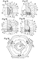
- Fig. 1
- einen Teil eines Axialschnitts durch eine erfindungsgemäße Einstellvorrichtung in Form eines Temperaturreglers mit einer Spannvorrichtung in Form einer Überwurfmutter, bevor diese nach der Montage an dem Gehäuse eines Heizkörperventils festgezogen worden ist,
- Fig. 2
- den gleichen Axialschnitt wie den nach Fig. 1, jedoch in einer Lage, in der die Einstellvorrichtung an einem Heizkörperventil befestigt ist, jedoch ohne das Heizkörperventil,
- Fig. 3
- eine Unteransicht der Einstellvorrichtung nach Fig. 1,
- Fig. 4
- die gleiche Schnittansicht wie die nach Fig. 1, jedoch ohne den im Schnappsitz darin eingesetzten ringförmigen Adapter,
- Fig. 5
- eine Innenansicht des Teils der Einstellvorrichtung nach Fig. 4 ohne den Adapter,
- Fig. 6
- den ringförmigen Adapter nach Fig. 1 im Axialschnitt,
- Fig. 7
- eine Draufsicht auf eine stirnseitige Verzahnung des Adapters nach Fig. 6,
- Fig. 8
- eine Unteransicht des Adapters nach Fig. 6,
- Fig. 9
- einen Axialschnitt eines Teils eines zweiten Ausführungsbeispiels einer erfindungsgemäßen Einstellvorrichtung in Form eines Temperaturreglers für ein Heizkörperventil im Schnitt IX-IX der Fig. 10,
- Fig. 10
- eine Unteransicht der Einstellvorrichtung nach Fig. 9,
- Fig. 11
- eine Ansicht eines Teils eines Stutzens der Einstellvorrichtung zum Anschließen an dem Gehäuse eines Heizkörperventils in der Schnittebene XI-XI der Fig. 13,
- Fig. 12
- einen vergrößerten Ausschnitt der Fig. 9,
- Fig. 13
- eine Innenansicht der Einstellvorrichtung gemäß Fig. 11 ohne den Adapter,
- Fig. 14
- eine Draufsicht des Adapters nach Fig. 9, und zwar auf eine mit der Verzahnung versehene Stirnseite,
- Fig. 15
- einen vergrößerten Ausschnitt eines dritten Ausführungsbeispiels einer erfindungsgemäßen Einstellvorrichtung,
- Fig. 16
- einen vergrößerten Ausschnitt eines fünften Ausführungsbeispiels einer erfindungsgemäßen Einstellvorrichtung,
- Fig. 17
- einen vergrößerten Ausschnitt eines sechsten Ausführungsbeispiels einer erfindungsgemäßen Einstellvorrichtung,
- Fig. 18
- eine Unteransicht eines siebten Ausführungsbeispiels einer erfindungsgemäßen Einstellvorrichtung,
- Fig. 19
- einen vergrößerten Ausschnitt der Einstellvorrichtung nach Fig. 18,
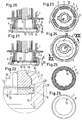
- Fig. 20
- einen Axialschnitt eines Teils eines achten Ausführungsbeispiels einer erfindungsgemäßen Einstellvorrichtung im Schnitt XX nach Fig. 24 im festgezogenen Zustand der Überwurfmutter,
- Fig. 21
- die gleiche Ansicht wie die nach Fig. 20, jedoch vor dem Festziehen der Überwurfmutter,
- Fig. 22
- einen vergrößerten Ausschnitt der Einstellvorrichtung nach Fig. 21,
- Fig. 23
- eine Unteransicht der Einstellvorrichtung nach Fig. 20, jedoch ohne den Adapter,
- Fig. 24
- eine Unteransicht der Einstellvorrichtung nach Fig. 20,
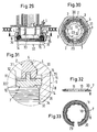
- Fig. 25
- eine Draufsicht auf die verzahnte Stirnseite des Adapters nach Fig. 20,
- Fig. 26
- eine Draufsicht auf die unverzahnte Stirnseite des Adapters nach Fig. 20,
- Fig. 27
- eine Unteransicht eines neunten Ausführungsbeispiels einer erfindungsgemäßen Einstellvorrichtung, teilweise im Schnitt,
- Fig. 28
- eine Querschnittsansicht eines weiteren Ausführungsbeispiels einer erfindungsgemäßen Einstellvorrichtung,
- Fig. 29
- einen Axialschnitt eines Teils eines weiteren Ausführungsbeispiels einer erfindungsgemäßen Einstellvorrichtung, die an einem Anschlußteil eines Stellventils eines Heizkörpers angebracht ist, jedoch vor dem Festziehen der Überwurfmutter,
- Fig. 30
- den Schnitt XXX-XXX der Fig. 29,
- Fig. 31
- einen vergrößerten Ausschnitt der Einstellvorrichtung nach Fig. 29,
- Fig. 32
- den Adapter der Einstellvorrichtung nach Fig. 29 im Axialschnitt,
- Fig. 33
- eine Draufsicht auf den Adapter nach Fig. 32,
- Fig. 34
- eine Vorderansicht einer Einstellvorrichtung in Form eines Temperaturreglers in einer relativen Drehwinkellage von 0° in bezug auf eine vertikale Ausrichtung einer Markierung an der Vorderseite des Gehäuses der Einstellvorrichtung und
- Fig. 35
- die gleiche Einstellvorrichtung wie die nach Fig. 29, jedoch in einer um 10° relativ zu einer vertikalen Ausrichtung auf einem Ventilgehäuse eingestellten Lage.
Claims (8)
- Einstellvorrichtung für ein Ventil, insbesondere Temperaturregler für ein Heizkörperventil, mit einem Stutzen (2) für den Anschluß an einen mit einer vorbestimmten Teilung profilierten Anschlußteil des Ventils; mit einem ringförmigen Adapter (7), der mit dem Stutzen (2) unverdrehbar kuppelbar ist und eine mit der Profilierung des Ventils unverdrehbar in Eingriff bringbare Profilierung (10) mit einer vorbestimmten Teilung aufweist; und mit einer den Stutzen (2) umgebenden Spannvorrichtung (5), dadurch gekennzeichnet, daß der Adapter (7) an dem Stutzen (2) im ungespannten Zustand der Spannvorrichtung (5) gegen ein unbeabsichtigtes axiales Entfernen arretierbar ist.
- Einstellvorrichtung nach Anspruch 1, dadurch gekennzeichnet, daß der Stutzen (2) mit einer Verzahnung (12) versehen ist und der Adapter (7) eine mit der Verzahnung (12) des Stutzens (2) unverdrehbar in Eingriff bringbare Verzahnung (11) mit einer vorbestimmten Teilung aufweist und am Stutzen (2) axial anbringbar ist; wobei wenigstens zwei aller Teilungen voneinander abweichen.
- Einstellvorrichtung nach Anspruch 1 oder 2, dadurch gekennzeichnet, daß der Adapter (7) im Schnappsitz am Stutzen (2) arretierbar ist.
- Einstellvorrichtung nach einem der Ansprüche 1 bis 3, dadurch gekennzeichnet, daß der Adapter (7) und der Stutzen (2) jeweils wenigstens einen radialen Rastvorsprung (8, 9; 19) aufweisen, die sich geringfügig überlappen und von denen wenigstens der eine (9; 19) der sich überlappenden Rastvorsprünge (8, 9; 19) durch den anderen beim Zusammensetzen von Stutzen (2) und Adapter (7) radial zur Seite gedrückt wird.
- Einstellvorrichtung nach Anspruch 2, dadurch gekennzeichnet, daß die Verzahnung (12) des Stutzens (2) am inneren Umfang oder einer radialen inneren Ringschulter oder einer Stirnseite des Stutzens (2) ausgebildet und die Verzahnung (11) des Adapters (7) der Verzahnung (12) des Stutzens (2) zugekehrt ist.
- Einstellvorrichtung nach Anspruch 2, dadurch gekennzeichnet, daß die Verzahnung (12) des Stutzens (2) an einer Stirnseite des Stutzens (2), die Verzahnung (11) des Adapters (7) an einer der Verzahnung (12) des Stutzens (2) zugekehrten Stirnseite des Adapters (7) und die Profilierung (10) des Adapters (7) an einer inneren Umfangsseite des Adapters (7) ausgebildet ist, daß die Spannvorrichtung (5) eine Überwurfmutter ist, die mit einem radial inneren Vorsprung (6) eine äußere Hinterschneidung (4) des Stutzens (2) hintergreift, daß der Adapter (7) in eine Ringnut (26) zwischen dem radialen Vorsprung (6) der Überwurfmutter (5) und ihrem Innengewinde (14) über das Innengewinde (14) hinweg einrastbar oder durch das Innengewinde (14) hindurch einschraubbar ist.
- Einstellvorrichtung nach einem der Ansprüche 2, 5 und 6, dadurch gekennzeichnet, daß nach dem Anbringen des Adapters (7) am Stutzen (2) die Verzahnungen (11, 12) durch das Spannen der Spannvorrichtung (5) in Eingriff gelangen und bis zum gegenseitigen Eingriff durch das Spannen ein hinreichendes axiales Spiel (15) zwischen Adapter (7) und Stutzen (2) verbleibt, das es ermöglicht, die Verzahnungen (11, 12) von Adapter (7) und Stutzen (2) für eine Verdrehung des Adapters (7) relativ zum Stutzen (2) und damit der Einstellvorrichtung in eine gewünschte Drehwinkellage relativ zum Ventil außer Eingriff zu halten.
- Einstellvorrichtung nach einem der Ansprüche 2, 5, 6 und 7, dadurch gekennzeichnet, daß die Teilungen der Verzahnung (12) des Stutzens (2) und der Verzahnung (11) des Adapters (7) gleich und kleiner als die Teilung der Profilierung (10) des Adapters (7) sind und die Teilung der Profilierung (10) des Adapters kleiner als die der Profilierung des Ventils ist.
Applications Claiming Priority (2)
| Application Number | Priority Date | Filing Date | Title |
|---|---|---|---|
| DE10104897A DE10104897A1 (de) | 2001-02-03 | 2001-02-03 | Einstellvorrichtung für ein Ventil |
| DE10104897 | 2001-02-03 |
Publications (2)
| Publication Number | Publication Date |
|---|---|
| EP1229416A1 true EP1229416A1 (de) | 2002-08-07 |
| EP1229416B1 EP1229416B1 (de) | 2003-12-10 |
Family
ID=7672745
Family Applications (1)
| Application Number | Title | Priority Date | Filing Date |
|---|---|---|---|
| EP02075324A Expired - Lifetime EP1229416B1 (de) | 2001-02-03 | 2002-01-25 | Positionierungsvorrichtung für ein Ventil |
Country Status (6)
| Country | Link |
|---|---|
| EP (1) | EP1229416B1 (de) |
| CN (1) | CN1237298C (de) |
| AT (1) | ATE256308T1 (de) |
| DE (2) | DE10104897A1 (de) |
| PL (1) | PL201565B1 (de) |
| RU (1) | RU2221180C2 (de) |
Cited By (2)
| Publication number | Priority date | Publication date | Assignee | Title |
|---|---|---|---|---|
| EP1388715A1 (de) * | 2002-08-08 | 2004-02-11 | Oliveira & Irmao S.A. | Vorrichtung zum Verbinden eines Einstellkopfes mit einem Thermostatventil, insbesondere für einen Heizkörper oder für andere Klima- oder Heizgeräte |
| WO2011000377A2 (de) | 2009-07-01 | 2011-01-06 | Danfoss A/S | Betätigungsaufsatz zur betätigung eines heizungsventils |
Citations (7)
| Publication number | Priority date | Publication date | Assignee | Title |
|---|---|---|---|---|
| DE2518443A1 (de) * | 1975-04-25 | 1977-03-17 | Heimeier Gmbh Metall Theodor | Thermostat fuer heizungsventile |
| DE3153654C2 (en) * | 1981-09-10 | 1990-09-06 | Theodor Heimeier Metallwerk Kg, 4782 Erwitte, De | Central heating system with individually controlled radiators |
| DE4344773A1 (de) * | 1993-12-28 | 1995-06-29 | Danfoss As | Thermostataufsatz für Heizkörperventile |
| DE29914101U1 (de) * | 1999-08-12 | 1999-11-18 | F.W. Oventrop GmbH & Co. KG, 59939 Olsberg | Einstellvorrichtung für Ventile |
| DE19909096A1 (de) * | 1999-03-02 | 2000-09-21 | Danfoss As | Thermostatventilaufsatz |
| DE19910224C1 (de) * | 1999-03-09 | 2000-11-30 | Heimeier Gmbh Metall Theodor | Thermostatkopf für Heizungsventile |
| DE19920864A1 (de) * | 1999-05-06 | 2000-12-07 | Heimeier Gmbh Metall Theodor | Thermostatventil-Kopf für Heizkörperventile |
Family Cites Families (5)
| Publication number | Priority date | Publication date | Assignee | Title |
|---|---|---|---|---|
| US3764102A (en) * | 1971-03-03 | 1973-10-09 | Robertshaw Controls Co | Fuel control device and system utilizing the same |
| US4234158A (en) * | 1979-07-16 | 1980-11-18 | Acf Industries, Incorporated | Combination tank car valve skid and valve seat wherein the skid is welded to the valve seat |
| DE3606951C2 (de) * | 1986-03-04 | 1994-11-03 | Erwes Pneumatic Gmbh | Bedienelement zur Verstellung des Solldrucks oder anderer Größen |
| US6038893A (en) * | 1994-10-03 | 2000-03-21 | Neelchine Engineering, Inc. | Lockout device |
| RU2169304C1 (ru) * | 1999-10-11 | 2001-06-20 | Закрытое акционерное общество "Криогенная технология" | Устройство для фиксации перекрывного органа клапана |
-
2001
- 2001-02-03 DE DE10104897A patent/DE10104897A1/de not_active Withdrawn
-
2002
- 2002-01-25 DE DE50200128T patent/DE50200128D1/de not_active Expired - Lifetime
- 2002-01-25 EP EP02075324A patent/EP1229416B1/de not_active Expired - Lifetime
- 2002-01-25 AT AT02075324T patent/ATE256308T1/de active
- 2002-01-28 PL PL351909A patent/PL201565B1/pl unknown
- 2002-02-01 RU RU2002102505/06A patent/RU2221180C2/ru not_active IP Right Cessation
- 2002-02-02 CN CNB021052662A patent/CN1237298C/zh not_active Expired - Fee Related
Patent Citations (7)
| Publication number | Priority date | Publication date | Assignee | Title |
|---|---|---|---|---|
| DE2518443A1 (de) * | 1975-04-25 | 1977-03-17 | Heimeier Gmbh Metall Theodor | Thermostat fuer heizungsventile |
| DE3153654C2 (en) * | 1981-09-10 | 1990-09-06 | Theodor Heimeier Metallwerk Kg, 4782 Erwitte, De | Central heating system with individually controlled radiators |
| DE4344773A1 (de) * | 1993-12-28 | 1995-06-29 | Danfoss As | Thermostataufsatz für Heizkörperventile |
| DE19909096A1 (de) * | 1999-03-02 | 2000-09-21 | Danfoss As | Thermostatventilaufsatz |
| DE19910224C1 (de) * | 1999-03-09 | 2000-11-30 | Heimeier Gmbh Metall Theodor | Thermostatkopf für Heizungsventile |
| DE19920864A1 (de) * | 1999-05-06 | 2000-12-07 | Heimeier Gmbh Metall Theodor | Thermostatventil-Kopf für Heizkörperventile |
| DE29914101U1 (de) * | 1999-08-12 | 1999-11-18 | F.W. Oventrop GmbH & Co. KG, 59939 Olsberg | Einstellvorrichtung für Ventile |
Cited By (4)
| Publication number | Priority date | Publication date | Assignee | Title |
|---|---|---|---|---|
| EP1388715A1 (de) * | 2002-08-08 | 2004-02-11 | Oliveira & Irmao S.A. | Vorrichtung zum Verbinden eines Einstellkopfes mit einem Thermostatventil, insbesondere für einen Heizkörper oder für andere Klima- oder Heizgeräte |
| WO2011000377A2 (de) | 2009-07-01 | 2011-01-06 | Danfoss A/S | Betätigungsaufsatz zur betätigung eines heizungsventils |
| WO2011000377A3 (de) * | 2009-07-01 | 2012-01-05 | Danfoss A/S | Betätigungsaufsatz zur betätigung eines heizungsventils |
| RU2503931C2 (ru) * | 2009-07-01 | 2014-01-10 | Данфосс А/С | Регулирующая насадка для управления радиаторным клапаном |
Also Published As
| Publication number | Publication date |
|---|---|
| EP1229416B1 (de) | 2003-12-10 |
| CN1237298C (zh) | 2006-01-18 |
| DE10104897A1 (de) | 2002-09-19 |
| DE50200128D1 (de) | 2004-01-22 |
| RU2221180C2 (ru) | 2004-01-10 |
| ATE256308T1 (de) | 2003-12-15 |
| PL201565B1 (pl) | 2009-04-30 |
| CN1369659A (zh) | 2002-09-18 |
Similar Documents
| Publication | Publication Date | Title |
|---|---|---|
| DE102018110718B4 (de) | Drehmoment-Steckschlüsseleinsatz mit einer Feststell- und Ausklinkfunktion | |
| EP3215750B1 (de) | Sicherungselement und sicherungssystem | |
| DE102007037242B4 (de) | Befestigungseinrichtung mit Toleranzausgleich | |
| DE19647742C2 (de) | Einrichtungs-Anziehvorrichtung für unverlierbare Schrauben | |
| DE19839342C2 (de) | Gerätesteckverbinder | |
| DE102004046414B4 (de) | Chirurgische Verankerungsvorrichtung | |
| EP3209888A1 (de) | Schnellbefestiger, verfahren zur verbindung von zwei bauteilen mittels des schnellbefestigers und herstellungsverfahren dafür | |
| WO1994026194A1 (de) | Knochenchirurgische haltevorrichtung | |
| EP0005865A2 (de) | Steckbares Verbindungssystem für Druckleitungen, insbesondere Bremssystem-Leitungen | |
| EP3586415B1 (de) | Steckerkupplung mit zugentlastung für ein verbindungskabel | |
| EP3428353A1 (de) | Wandhalterung für einen sanitärartikel | |
| DE19912474C2 (de) | Befestigungsanordnung für die Anbringung eines Bauteils an einer C-förmigen Halteschiene | |
| DE112008003273B4 (de) | Regulierungssystem zum Regulieren von Zahn- und/oder Kieferfehlstellungen | |
| EP0683931B1 (de) | Befehls- und/oder meldegerät | |
| EP3091240B1 (de) | Vorrichtung und anordnung zur verriegelung von schraubbaren elementen | |
| DE2541127C3 (de) | Bajonettkupplung | |
| EP1229416B1 (de) | Positionierungsvorrichtung für ein Ventil | |
| DE102013009358B4 (de) | Konstruktion zur Einstellung des Drehmoments am Schraubendreher | |
| DE20213362U1 (de) | Befestigungsanordnung für eine Heckleuchte | |
| EP1004713A2 (de) | Abdeck-Rosette | |
| EP0955479B1 (de) | Vorrichtung zum Verbinden von Bauteilen | |
| DE29704808U1 (de) | Heizkörper-Abstandsvorrichtung zum Fixieren eines Abstandes eines Heizkörpers von einem Gebäudeteil | |
| EP0860617B2 (de) | Hammerkopfschraube für eine Deckenbefestigung | |
| EP1426632A1 (de) | Befestigungselement | |
| DE102004048363B4 (de) | Schraube |
Legal Events
| Date | Code | Title | Description |
|---|---|---|---|
| PUAI | Public reference made under article 153(3) epc to a published international application that has entered the european phase |
Free format text: ORIGINAL CODE: 0009012 |
|
| AK | Designated contracting states |
Kind code of ref document: A1 Designated state(s): AT BE CH CY DE DK ES FI FR GB GR IE IT LI LU MC NL PT SE TR |
|
| AX | Request for extension of the european patent |
Free format text: AL;LT;LV;MK;RO;SI |
|
| 17P | Request for examination filed |
Effective date: 20020823 |
|
| 17Q | First examination report despatched |
Effective date: 20021120 |
|
| AKX | Designation fees paid |
Designated state(s): AT DE FR GB |
|
| GRAH | Despatch of communication of intention to grant a patent |
Free format text: ORIGINAL CODE: EPIDOS IGRA |
|
| GRAS | Grant fee paid |
Free format text: ORIGINAL CODE: EPIDOSNIGR3 |
|
| GRAA | (expected) grant |
Free format text: ORIGINAL CODE: 0009210 |
|
| AK | Designated contracting states |
Kind code of ref document: B1 Designated state(s): AT DE FR GB |
|
| REG | Reference to a national code |
Ref country code: GB Ref legal event code: FG4D Free format text: NOT ENGLISH |
|
| REG | Reference to a national code |
Ref country code: IE Ref legal event code: FG4D Free format text: GERMAN |
|
| REF | Corresponds to: |
Ref document number: 50200128 Country of ref document: DE Date of ref document: 20040122 Kind code of ref document: P |
|
| GBT | Gb: translation of ep patent filed (gb section 77(6)(a)/1977) |
Effective date: 20040225 |
|
| REG | Reference to a national code |
Ref country code: IE Ref legal event code: FD4D |
|
| ET | Fr: translation filed | ||
| PLBE | No opposition filed within time limit |
Free format text: ORIGINAL CODE: 0009261 |
|
| STAA | Information on the status of an ep patent application or granted ep patent |
Free format text: STATUS: NO OPPOSITION FILED WITHIN TIME LIMIT |
|
| 26N | No opposition filed |
Effective date: 20040913 |
|
| REG | Reference to a national code |
Ref country code: FR Ref legal event code: PLFP Year of fee payment: 15 |
|
| PGFP | Annual fee paid to national office [announced via postgrant information from national office to epo] |
Ref country code: FR Payment date: 20151208 Year of fee payment: 15 |
|
| PGFP | Annual fee paid to national office [announced via postgrant information from national office to epo] |
Ref country code: DE Payment date: 20160119 Year of fee payment: 15 |
|
| PGFP | Annual fee paid to national office [announced via postgrant information from national office to epo] |
Ref country code: AT Payment date: 20151223 Year of fee payment: 15 Ref country code: GB Payment date: 20160120 Year of fee payment: 15 |
|
| REG | Reference to a national code |
Ref country code: DE Ref legal event code: R119 Ref document number: 50200128 Country of ref document: DE |
|
| REG | Reference to a national code |
Ref country code: AT Ref legal event code: MM01 Ref document number: 256308 Country of ref document: AT Kind code of ref document: T Effective date: 20170125 |
|
| GBPC | Gb: european patent ceased through non-payment of renewal fee |
Effective date: 20170125 |
|
| REG | Reference to a national code |
Ref country code: FR Ref legal event code: ST Effective date: 20170929 |
|
| PG25 | Lapsed in a contracting state [announced via postgrant information from national office to epo] |
Ref country code: AT Free format text: LAPSE BECAUSE OF NON-PAYMENT OF DUE FEES Effective date: 20170125 Ref country code: FR Free format text: LAPSE BECAUSE OF NON-PAYMENT OF DUE FEES Effective date: 20170131 |
|
| PG25 | Lapsed in a contracting state [announced via postgrant information from national office to epo] |
Ref country code: GB Free format text: LAPSE BECAUSE OF NON-PAYMENT OF DUE FEES Effective date: 20170125 Ref country code: DE Free format text: LAPSE BECAUSE OF NON-PAYMENT OF DUE FEES Effective date: 20170801 |