EP1229296A1 - Louvered fin for a heat exchanger - Google Patents
Louvered fin for a heat exchanger Download PDFInfo
- Publication number
- EP1229296A1 EP1229296A1 EP02002267A EP02002267A EP1229296A1 EP 1229296 A1 EP1229296 A1 EP 1229296A1 EP 02002267 A EP02002267 A EP 02002267A EP 02002267 A EP02002267 A EP 02002267A EP 1229296 A1 EP1229296 A1 EP 1229296A1
- Authority
- EP
- European Patent Office
- Prior art keywords
- corrugated strip
- louvers
- corrugated
- tubes
- blank
- Prior art date
- Legal status (The legal status is an assumption and is not a legal conclusion. Google has not performed a legal analysis and makes no representation as to the accuracy of the status listed.)
- Withdrawn
Links
Images


Classifications
-
- F—MECHANICAL ENGINEERING; LIGHTING; HEATING; WEAPONS; BLASTING
- F28—HEAT EXCHANGE IN GENERAL
- F28F—DETAILS OF HEAT-EXCHANGE AND HEAT-TRANSFER APPARATUS, OF GENERAL APPLICATION
- F28F1/00—Tubular elements; Assemblies of tubular elements
- F28F1/10—Tubular elements and assemblies thereof with means for increasing heat-transfer area, e.g. with fins, with projections, with recesses
- F28F1/12—Tubular elements and assemblies thereof with means for increasing heat-transfer area, e.g. with fins, with projections, with recesses the means being only outside the tubular element
- F28F1/126—Tubular elements and assemblies thereof with means for increasing heat-transfer area, e.g. with fins, with projections, with recesses the means being only outside the tubular element consisting of zig-zag shaped fins
- F28F1/128—Fins with openings, e.g. louvered fins
-
- B—PERFORMING OPERATIONS; TRANSPORTING
- B21—MECHANICAL METAL-WORKING WITHOUT ESSENTIALLY REMOVING MATERIAL; PUNCHING METAL
- B21D—WORKING OR PROCESSING OF SHEET METAL OR METAL TUBES, RODS OR PROFILES WITHOUT ESSENTIALLY REMOVING MATERIAL; PUNCHING METAL
- B21D53/00—Making other particular articles
- B21D53/02—Making other particular articles heat exchangers or parts thereof, e.g. radiators, condensers fins, headers
- B21D53/08—Making other particular articles heat exchangers or parts thereof, e.g. radiators, condensers fins, headers of both metal tubes and sheet metal
- B21D53/085—Making other particular articles heat exchangers or parts thereof, e.g. radiators, condensers fins, headers of both metal tubes and sheet metal with fins places on zig-zag tubes or parallel tubes
-
- F—MECHANICAL ENGINEERING; LIGHTING; HEATING; WEAPONS; BLASTING
- F28—HEAT EXCHANGE IN GENERAL
- F28D—HEAT-EXCHANGE APPARATUS, NOT PROVIDED FOR IN ANOTHER SUBCLASS, IN WHICH THE HEAT-EXCHANGE MEDIA DO NOT COME INTO DIRECT CONTACT
- F28D1/00—Heat-exchange apparatus having stationary conduit assemblies for one heat-exchange medium only, the media being in contact with different sides of the conduit wall, in which the other heat-exchange medium is a large body of fluid, e.g. domestic or motor car radiators
- F28D1/02—Heat-exchange apparatus having stationary conduit assemblies for one heat-exchange medium only, the media being in contact with different sides of the conduit wall, in which the other heat-exchange medium is a large body of fluid, e.g. domestic or motor car radiators with heat-exchange conduits immersed in the body of fluid
- F28D1/04—Heat-exchange apparatus having stationary conduit assemblies for one heat-exchange medium only, the media being in contact with different sides of the conduit wall, in which the other heat-exchange medium is a large body of fluid, e.g. domestic or motor car radiators with heat-exchange conduits immersed in the body of fluid with tubular conduits
- F28D1/0408—Multi-circuit heat exchangers, e.g. integrating different heat exchange sections in the same unit or heat exchangers for more than two fluids
- F28D1/0426—Multi-circuit heat exchangers, e.g. integrating different heat exchange sections in the same unit or heat exchangers for more than two fluids with units having particular arrangement relative to the large body of fluid, e.g. with interleaved units or with adjacent heat exchange units in common air flow or with units extending at an angle to each other or with units arranged around a central element
- F28D1/0435—Combination of units extending one behind the other
-
- F—MECHANICAL ENGINEERING; LIGHTING; HEATING; WEAPONS; BLASTING
- F28—HEAT EXCHANGE IN GENERAL
- F28F—DETAILS OF HEAT-EXCHANGE AND HEAT-TRANSFER APPARATUS, OF GENERAL APPLICATION
- F28F2215/00—Fins
- F28F2215/02—Arrangements of fins common to different heat exchange sections, the fins being in contact with different heat exchange media
-
- Y—GENERAL TAGGING OF NEW TECHNOLOGICAL DEVELOPMENTS; GENERAL TAGGING OF CROSS-SECTIONAL TECHNOLOGIES SPANNING OVER SEVERAL SECTIONS OF THE IPC; TECHNICAL SUBJECTS COVERED BY FORMER USPC CROSS-REFERENCE ART COLLECTIONS [XRACs] AND DIGESTS
- Y10—TECHNICAL SUBJECTS COVERED BY FORMER USPC
- Y10T—TECHNICAL SUBJECTS COVERED BY FORMER US CLASSIFICATION
- Y10T29/00—Metal working
- Y10T29/49—Method of mechanical manufacture
- Y10T29/4935—Heat exchanger or boiler making
- Y10T29/49366—Sheet joined to sheet
-
- Y—GENERAL TAGGING OF NEW TECHNOLOGICAL DEVELOPMENTS; GENERAL TAGGING OF CROSS-SECTIONAL TECHNOLOGIES SPANNING OVER SEVERAL SECTIONS OF THE IPC; TECHNICAL SUBJECTS COVERED BY FORMER USPC CROSS-REFERENCE ART COLLECTIONS [XRACs] AND DIGESTS
- Y10—TECHNICAL SUBJECTS COVERED BY FORMER USPC
- Y10T—TECHNICAL SUBJECTS COVERED BY FORMER US CLASSIFICATION
- Y10T29/00—Metal working
- Y10T29/49—Method of mechanical manufacture
- Y10T29/4935—Heat exchanger or boiler making
- Y10T29/49377—Tube with heat transfer means
- Y10T29/49378—Finned tube
- Y10T29/4938—Common fin traverses plurality of tubes
Definitions
- the present invention relates to a vehicular heat exchanger, particularly to a louvered fin for a heat exchanger, which has (a) a corrugated strip having planar and connecting portions that are alternately arranged to make a corrugation and (b) a plurality of louvers formed in each planar portion such that the louvers are arranged in a lateral direction, to a heat exchanger having such louvered fin, and to a method for producing such heat exchanger.
- a heat exchanger such as radiator is disposed at a front position in an engine room, and this radiator serves to cool an engine cooling water.
- this radiator has a pair of tanks (headers), a plurality of tubes extending between the tanks, and a plurality of fins each being disposed between two adjacent tubes. At the position of each fin, a heat exchange is conducted between air flowing through the fins and the cooling water passing through the tube.
- louvered fin for a heat exchanger.
- This louvered fin comprises:
- a heat exchanger comprising a first assembly.
- the first assembly includes:
- Fig. 12 shows a louvered fin 1 not according to the present invention.
- This louvered fin 1 is made of a thin strip 2 and has corner portions 1a and planar portions 1b that are alternately continuously arranged to make a corrugation.
- Each planar portion 1b has a plurality of louvers 3 that are arranged in the lateral direction and are orientated obliquely relative to the base flat wall of the planar portion 1b.
- louvered fin 1 becomes imbalanced in the lateral direction. With this, the louvered fin 1 tends to curl, as shown in Fig. 13. This makes impossible to conduct an automated assembly of this louvered fin 1 for producing a heat exchanger.
- the present invention was made in view of such problem.
- the present invention makes it possible to prevent curling of a louvered fin of a heat exchanger in the production of the heat exchanger, even if its louvers are in asymmetry in the lateral direction, and thereby makes it possible to conduct an automated assembly of louvered fin for producing a heat exchanger.
- the louvered fin according to the present invention has the straightening member extending along a longitudinal side of the first corrugated strip.
- This straightening member is capable of preventing the above-mentioned curling of a louvered fin during the production of a heat exchanger, even if the first louvers in each planar portion are configured to be in asymmetry in the lateral direction and even if planar portions each having such asymmetrical louvers are continuously formed in the longitudinal direction of the louvered fin. Therefore, when the first corrugated strip is disposed or fixed between first and second tubes of a heat exchanger, it is possible to maintain the first corrugated strip in a straight shape. Therefore, it becomes possible to easily and precisely conduct an assembly of the louvered fin.
- the straightening member from the first corrugated strip by breaking the first bridge member after the first corrugated strip is fixed between the first and second tubes.
- the first corrugated strip has a fracture surface only at one longitudinal side of the first corrugated strip.
- the other longitudinal side does not have such fracture surface. Therefore, the existence of this fracture surface makes it easy to recognize the proper orientation of the louvered fin and thereby to conduct the proper assembly of the louvered fin.
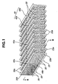
- FIG. 1 shows a louvered fin according to an embodiment of the present invention.
- This louvered fin has a first corrugated strip 23 and a second corrugated strip 33.
- the second corrugated strip 33 is capable of serving as the straightening member for keeping the first corrugated strip 23 in a straight shape in the longitudinal direction of the first corrugated strip 23.
- the first and second corrugated strips 23 and 24 are respectively simultaneously used for producing first and second radiators (first and second assemblies) 20 and 30.
- a first sandwiched structure having the first corrugated strip 23 fixed between first and second adjacent tubes 22, 22 is detached from a second sandwiched structure having the second corrugated strip 33 fixed between third and fourth adjacent tubes 32, 32 for simultaneously producing the first and second radiators 20 and 30.
- the first radiator 20 has first and second tanks (headers) 21 and 21a and a plurality of tubes 22 extending between the first and second tanks 21 and 21a such that a heat-exchanger medium (cooling water) is allowed to flow from one of the first and second tanks 21 and 21a to the other tank.
- the first radiator 20 further has the first corrugated strip 23 that is fixed between first and second adjacent tubes 22, 22 by brazing.
- the first and second tanks 21 and 21a are attached to the above-mentioned first sandwiched structure for producing the first radiator 20.
- the first sandwiched structure is reinforced at its both sides with a pair of reinforcements 24 and 24a.
- the second radiator 30 has a construction substantially identical with that of the first radiator 20.
- the second radiator 30 has third and fourth tanks (headers) 31 and 31a and a plurality of tubes 32 extending between the third and fourth tanks 31 and 31a such that a heat-exchanger medium (cooling water) is allowed to flow from one of the third and fourth tanks 31 and 31a to the other tank.
- the second radiator 30 further has the second corrugated strip 33 that is fixed between third and fourth adjacent tubes 32 by brazing.
- the third and fourth tanks 31 and 31a are attached to the above-mentioned second sandwiched structure for producing the second radiator 30.
- the second sandwiched structure is reinforced at its both sides with a pair of reinforcements 34 and 34a.
- each tube 22 or 32 has a compressed configuration having opposite sides parallel with each other.
- Each tube is inserted at its both ends to insertion holes (not shown in the drawings) of the tanks and is fixed to the tanks by brazing.
- each reinforce is also fixed at its both ends to the tanks by brazing. While a heat-exchanger medium flows through each tube, heat of this medium is transmitted to the first or second corrugated strip 23 or 33 and then to the air flowing therethrough, thereby conducing a heat exchange with the air and cooling of the heat-exchanger medium.
- the louvered fin has at its center in the longitudinal direction a perforated portion 40 at a boundary between the first and second corrugated strips 23 and 33.
- the perforated portion 40 has a plurality of bridge members 40a each being defined between adjacent slits 40b in the longitudinal direction. These bridge members 40a are broken for detaching the first and second corrugated strips 23 and 33 from each other, after each corrugated strip 23 or 33 is fixed between corresponding two adjacent tubes. This makes it possible to prevent curling of each corrugated strip 23 or 33.
- Each of the first and second corrugated strips 23 and 33 is a thin strip made of aluminum and has planar portions 23b or 33b and connecting portions (bent portions) 23a or 33a that are alternately continuously arranged to make a corrugation. Furthermore, as shown in Figs. 1 and 6, first louvers 25 are formed in each planar portion 23b such that the first louvers 25 in each planar portion 23b are arranged in the lateral direction of the first corrugated strip 23 and are configured to be in asymmetry in the lateral direction. In other words, the first louvers 25 in each planar portion 23b are orientated obliquely in a first uniform direction relative to the base wall of the planar portion 23b.
- the first louvers 25 have their openings 25a that are orientated obliquely relative to the base wall of the planar portion 23b.
- the first louvers 25 in each planar portion 23b are asymmetrical in the lateral direction about the center line C1 of the planar portion 23b.
- second louvers 35 are formed in each planar portion 33b such that the second louvers 35 in each planar portion 33b are arranged in the lateral direction of the first corrugated strip 23 and are configured to be in asymmetry in the lateral direction.
- the second louvers 35 in each planar portion 33b are orientated obliquely in a second uniform direction relative to the base wall of the planar portion 33b. That is, the second louvers 35 have their openings 35a that are orientated obliquely relative to the base wall of the planar portion 33b.
- the second louvers 35 in each planar portion 33b are asymmetrical in the lateral direction about the center line C2 of the planar portion 33b.
- first and second louvers 25 and 35 are symmetrical to each other about the perforated portion 40.
- Each of the first and second louvers 25 and 35 is formed by cutting the base wall of the planar portion 23b or 33b and by raising a predetermined portion of the base wall.
- a method for producing the louvered fin will be explained in detail in the following.
- a blank 51 in the form of thin strip or ribbon
- the blank 51 is perforated by passing the blank 51 between a pair of perforation forming rollers 52, thereby perforating the blank 51 at regular intervals in a longitudinal direction of the blank 51.
- a first blank of the first corrugated strip 23 a second blank of the second corrugated strip 33, and bridge members 40a each being provided between adjacent first and second perforations (slits) (see Fig. 8).
- the blank 61 is passed between a pair of corrugation forming rollers 53.
- the first and second louvers 25 and 35 are formed, and at the same time the blank 51 is shaped into a corrugated blank by bending the blank 51 at a position of each bridge member 40a in the lateral direction.
- the corrugation forming rollers 58 have a plurality of star-like gears (not shown in the drawings) that are meshed with each other by turning the corrugation forming rollers 53, for making a corrugation.
- Each star-like gear is formed with teeth for forming the first and second louvers 25 and 35.
- the pitch of the corrugated blank i.e., the distance between adjacent connecting portions 23a or 33a
- the corrugated blank is cut to have a predetermined length.
- the resulting louvered fin shown in Fig. 1 is formed with the first and second corrugated strips 23 and 33 attached with each other by the bridge members 40a.
- the first and second louvers 25 and 35 are respectively orientated in the first and second directions that are opposite to each other.
- the openings of the first louvers 25 are symmetrical to those of the second louvers 35 about the perforated portion 40.
- the perforated portion 40 has bridge members 40a each defined by adjacent slits 40b.
- the bridge members 40a are formed at positions of connecting portions 23a and 33a at regular intervals (at every 8 connecting portions 23a and 33a in Fig. 1).
- the slit 40b may have a certain width (see Figs. 1 and 8) or no width (not shown in the drawings) in the lateral direction. In the latter case, the slit 40b is a cut having no width. In this case, it is possible to get rid of wastes generated by preparing the slits of a certain width.
- a first sandwiched structure is prepared by alternately disposing the first corrugated strips 23 and the tubes 22 and by putting reinforces 24 and 24a at both ends. As shown in Fig. 3, the first corrugated strip 23 at the top position is disposed between the reinforce 24 and the tube 22. Similarly, that at the bottom position is disposed between the reinforce 24a and the tube 22. The other first corrugated strips 23 are each disposed between corresponding two adjacent tubes 22.
- a second sandwiched structure is also prepared by substantially the same manner, thereby preparing an integral body of the first and second sandwiched structures.
- the first and second sandwiched structures which are attached with each other through the bridge members 40a, are pre-assemblies of the first and second radiators 20 and 30.
- all of the louvered fins are properly orientated such that all of the first louvers 25 of all the first corrugated fins 23 are orientated in a first uniform direction and such that all of the second louvers 35 of all the second corrugated fins 33 are orientated in a second uniform direction that is opposite to the first uniform direction (see Fig. 6).
- the first and second sandwiched structures are detached from each other by breaking the bridge members 40a under a condition that upward and downward forces F are added to the first and second sandwiched structures in order to press the first and second corrugated strips 23 and 33 and the corresponding tubes 22 and 32 against each other.
- This detachment can be conducted by applying a vibration shock in the longitudinal direction of the louvered fins at a position corresponding to the bridge members 40a.
- this vibration shock shearing force
- the first and second corrugated strips 23 and 33 are forced to move relative to each other, thereby easily breaking the bridge members 40a.
- each of the first and second corrugated strips 23 and 33 is formed at its one longitudinal side with fracture surfaces 41 when the first and second sandwiched structures are separated from each other.
- the first and second structures are rotated relative to each other by about 90 degrees to make a cross-like shape.
- the first and second tanks 21 and 21a are attached to the first sandwiched structure
- the third and fourth tanks 31 and 31a are attached to the second sandwiched structure.
- the former attachment is conducted by inserting end portions of the tubes 22 and of the reinforces 24 and 24a into predetermined holes of the first and second tanks 21 and 21a, followed by brazing.
- the latter attachment is conducted by inserting end portions of the tubes 32 and of the reinforces 34 and 34a into predetermined holes of the third and fourth tanks 31 and 31a, followed by brazing.
- the first and second corrugated strips 23 are put alongside of each other and attached with each other by the bridge members 40a.
- the first and second louvers 25 and 35 of all the first and second corrugated strips 23 and 33 are respectively orientated in a first uniform direction and a second uniform direction that is opposite to the first uniform direction. Therefore, as shown in Fig. 10, as long as the first and second corrugated strips 23 and 33 are attached with each other, the second corrugated strip 33 prevents the first corrugated strip 23 from curling in one direction, and the first corrugated strip 23 prevents the second corrugated strip 33 from curling in the other direction.
- first and second corrugated strips 23 and 33 are detached from each other under a condition that each of the first and second corrugated strips 23 and 33 is not fixed between two adjacent tubes, the first and second corrugated strips 23 and 33 tend to curl in one and the other directions, respectively.
- the detachment is conducted under a condition that each of the first and second corrugated strips 23 and 33 is fixed between two adjacent tubes. Therefore, it is certainly possible to prevent curling of the first and second corrugated strips 23 and 33 and thereby to keep these strips in the straight form. This makes it possible to simultaneously conduct an automated assembly of the first and second radiators.
- each bridge member 40a between two adjacent slits 40b has a relatively short width in the longitudinal direction of the louvered fin. Therefore, it is easily possible to break the bridge members 40a by applying shearing force.
- each bridge member 40a is formed between the laterally aligned connecting portions (bent portions) 23a and 33a of the first and second corrugated strips 23 and 33. These connecting portions 28a and 33a are greater than the planar portions 23b and 33b in rigidity. Therefore, it is possible to prevent deformation of the first and second corrugated strips 23 and 33 caused by applying a breaking load to the bridge members 40a, as compared with a case in which each bridge member is formed between the planar portions.
- each of the first and second corrugated strips 23 and 33 has a fracture surface only at one longitudinal side thereof.
- the other longitudinal side does not have such fracture surface. Therefore, the existence of this fracture surface makes it easy to recognize the proper orientation of the louvered fin. This also makes it possible to easily recognize the front or rear surface of the first and second radiators 20 and 30, thereby improving the assembly efficiency of these radiators.
- the openings 25a or 35a of the first or second louvers 25 or 35 are orientated in a uniform direction. Therefore, it is possible to prevent air from flowing in a meandering manner through the first or second corrugated strips 23 or 33. This provides a smooth air flow and increases the amount of air flowing therethrough, thereby improving heat exchange efficiency.
- Figs. 11(a) and 11(b) show sequential steps for forming a corrugated blank of the louvered fin in accordance with another embodiment of the present invention.
- a V-shaped portion (groove) 42 is formed at first at a position corresponding to each connecting portion 23a or 33a of the first and second corrugated strips 23 and 33 (see Fig. 11(a)). Then, each V-shaped portion 42 is straightened into the connecting portion 23a or 33a that is planar in shape (see Fig. 11(b)).
- This planar connecting portion 23a or 33a is improved in preventing deformation of the connecting portions when a breaking load acts on the bridge members 40a.
- planar connecting portions 23a or 33a are capable of making the planar portions 23b or 33b longer in effective length L (see Fig. 11(b)), as compared with the case of arcuate connecting portions. Therefore, it is possible to make the widths of the first and second corrugated strips 25 and 35 longer, thereby making their opening areas greater. With this, it is possible to increase the amount of air flowing therethrough and to improve the heat exchange efficiency.
- the straightening member is not limited to the second corrugated strip 35.
- the straightening member may be a ribbon having no louvers.
- the straightening member is attached to the first corrugated strip through the bridge member and is subjected to a separation from the first corrugated strip in the production of a heat exchanger, as described above.
- the present invention is not limited to that the first or second louvers 25 or 35 in each planar portion 23b or 33b are orientated in a uniform direction (Fig. 6).
- the first and/or second corrugated strips 23 and 33 tend to have the above-mentioned curling. Therefore, the present invention can be used in this case, too.
- first or second corrugated strip 23 or 33 It is optional in the present invention to conduct a brazing between the first or second corrugated strip 23 or 33 and two adjacent tubes 22 or 32 and then to conduct a detachment of the first and second corrugated strips 23 and 33 from each other.
- a heat exchanger according to the present invention is not limited to the above-mentioned first and second radiators 20 and 30.
- the heat exchanger may be a heater core or an evaporator in cooling cycle.
Abstract
The invention relates to a louvered fin for a heat
exchanger. This louvered fin includes (a) a first corrugated
strip having planar and connecting portions that are
alternately arranged to make a corrugation, the first
corrugated strip extending straight in a longitudinal direction;
(b) first louvers formed in each planar portion such that the
first louvers are arranged in a lateral direction, the first
louvers in each planar portion being configured to be in
asymmetry in the lateral direction; (c) a straightening member
for keeping the first corrugated strip in a straight shape in the
longitudinal direction, the straightening member extending
along a longitudinal side of the first corrugated strip; and (d) a
first bridge member for attaching the first corrugated strip and
the straightening member together.
Description
- The present invention relates to a vehicular heat exchanger, particularly to a louvered fin for a heat exchanger, which has (a) a corrugated strip having planar and connecting portions that are alternately arranged to make a corrugation and (b) a plurality of louvers formed in each planar portion such that the louvers are arranged in a lateral direction, to a heat exchanger having such louvered fin, and to a method for producing such heat exchanger.
- In an automotive water-cooled engine, a heat exchanger such as radiator is disposed at a front position in an engine room, and this radiator serves to cool an engine cooling water. As generally known, this radiator has a pair of tanks (headers), a plurality of tubes extending between the tanks, and a plurality of fins each being disposed between two adjacent tubes. At the position of each fin, a heat exchange is conducted between air flowing through the fins and the cooling water passing through the tube.
- It is an object of the present invention to provide a louvered fin for a heat exchanger, which louvered fin is prevented from curling in the production of the heat exchanger, even if louvers of the louvered fin are in asymmetry in its lateral direction.
- It is another object of the present invention to provide a heat exchanger produced by using such louvered fin.
- It is still another object of the present invention to provide a method for producing such heat exchanger.
- According to the present invention, there is provided a louvered fin for a heat exchanger. This louvered fin comprises:
- a first corrugated strip having planar and connecting portions that are alternately arranged to make a corrugation, the first corrugated strip extending straight in a longitudinal direction;
- a plurality of first louvers formed in each planar portion such that the first louvers are arranged in a lateral direction perpendicular to the longitudinal direction, the first louvers in each planar portion being configured to be in asymmetry in the lateral direction;
- a straightening member for keeping the first corrugated strip in a straight shape in the longitudinal direction, the straightening member extending along a longitudinal side of the first corrugated strip; and
- a first bridge member for attaching the first corrugated strip and the straightening member together such that a detachment of the straightening member from the first corrugated strip is allowed by breaking the first bridge member after the first corrugated strip is fixed between first and second adjacent tubes of the heat exchanger in a production of the heat exchanger.
-
- According to the present invention, there is provided a heat exchanger comprising a first assembly. The first assembly includes:
- first and second tanks;
- first and second tubes extending between the first and second tanks such that a heat-exchanger medium is allowed to flow from the first tank to the second tank;
- the first corrugated strip fixed between the first and second tubes, the first corrugated strip having a fracture surface at a longitudinal side of the first corrugated strip; and
- the first louvers. This heat exchanger is produced by a
method comprising the steps of:
- (1) providing a louvered fin comprising (a) the first corrugated strip; (b) the first louvers; (c) a straightening member for keeping the first corrugated strip in a straight shape in the longitudinal direction, the straightening member extending along a longitudinal side of the first corrugated strip; and (d) a first bridge member for attaching the first corrugated strip and the straightening member together;
- (2) fixing the first corrugated strip between the first and second tubes such that the first corrugated strip is kept in the straight shape by the first and second tubes; and
- (3) detaching the straightening member from the first corrugated strip by breaking the first bridge member such that there is provided a sandwiched structure having the first corrugated strip fixed between the first and second tubes and such that the fracture surface of the first corrugated strip is exposed.
-
-
- Fig. 1 is a perspective view showing a louvered fin according to an embodiment of the present invention;
- Figs. 2-4 are perspective views showing sequential steps for producing a heat exchanger in accordance with an embodiment of the present invention;
- Fig. 5 is an end view showing a radiator tube according to an embodiment of the present invention;
- Fig. 6 is a sectional view taken along the lines B-B in Fig. 1;
- Fig. 7 is a schematic view showing steps for producing the louvered fin;
- Fig. 8 is a plan view showing a blank of the louvered fin;
- Fig. 9 is a perspective view showing a first corrugated strip having a fracture surface formed by detaching a straightening member from the first corrugated strip;
- Fig. 10 is a plan view showing another blank of the louvered fin;
- Figs. 11(a) and 11(b) are side views showing sequential steps for forming a corrugated blank of the louvered fin in accordance with another embodiment of the present invention;
- Fig. 12 is a partial perspective view showing a louvered fin not according to the present invention;
- Fig. 13 is a perspective view showing a condition of curling of the louvered fin of Fig. 12; and
- Fig. 14 is a laterally sectional view of the louvered fin of Fig. 12.
-
- Fig. 12 shows a louvered fin 1 not according to the present invention. This louvered fin 1 is made of a
thin strip 2 and hascorner portions 1a andplanar portions 1b that are alternately continuously arranged to make a corrugation. Eachplanar portion 1b has a plurality oflouvers 3 that are arranged in the lateral direction and are orientated obliquely relative to the base flat wall of theplanar portion 1b. - In case that all the
louvers 3 in eachplanar portion 1b are orientated in a uniform direction, the louvered fin 1 becomes imbalanced in the lateral direction. With this, the louvered fin 1 tends to curl, as shown in Fig. 13. This makes impossible to conduct an automated assembly of this louvered fin 1 for producing a heat exchanger. In order to prevent this curling, there is a proposal in which the left half andright half louvers planar portion 1b, as shown in Fig. 14. This proposal makes it possible to maintain the louvered fin 1 in a straight shape in its longitudinal direction. - However, according to the above proposal, air flows from a first side F1 of the
planar portion 1b to a second side F2 through thelouvers 3a, as shown by the arrow of two-dot chain line in Fig. 14. Then, air flows from the second side F2 to the first side F1 through thelouvers 3b due to the orientation of thelouvers 3b. Therefore, air flows through the louvered fin 1 in a meandering manner. This increases air flow resistance and thereby lowers heat exchange efficiency. - The present invention was made in view of such problem. The present invention makes it possible to prevent curling of a louvered fin of a heat exchanger in the production of the heat exchanger, even if its louvers are in asymmetry in the lateral direction, and thereby makes it possible to conduct an automated assembly of louvered fin for producing a heat exchanger.
- As stated above, the louvered fin according to the present invention has the straightening member extending along a longitudinal side of the first corrugated strip. This straightening member is capable of preventing the above-mentioned curling of a louvered fin during the production of a heat exchanger, even if the first louvers in each planar portion are configured to be in asymmetry in the lateral direction and even if planar portions each having such asymmetrical louvers are continuously formed in the longitudinal direction of the louvered fin. Therefore, when the first corrugated strip is disposed or fixed between first and second tubes of a heat exchanger, it is possible to maintain the first corrugated strip in a straight shape. Therefore, it becomes possible to easily and precisely conduct an assembly of the louvered fin. It is possible to detach the straightening member from the first corrugated strip by breaking the first bridge member after the first corrugated strip is fixed between the first and second tubes. By this breaking, the first corrugated strip has a fracture surface only at one longitudinal side of the first corrugated strip. The other longitudinal side does not have such fracture surface. Therefore, the existence of this fracture surface makes it easy to recognize the proper orientation of the louvered fin and thereby to conduct the proper assembly of the louvered fin. For example, it is possible to easily recognize one longitudinal side (having the fracture surface) as the front or rear side in the production of a heat exchanger. This improves the assembly workability of a heat exchanger.
- With reference to Figs. 1-10, 11(a) and 11(b), exemplary embodiments according to the present invention will be described in detail in the following. Fig. 1 shows a louvered fin according to an embodiment of the present invention. This louvered fin has a first
corrugated strip 23 and a secondcorrugated strip 33. The secondcorrugated strip 33 is capable of serving as the straightening member for keeping the firstcorrugated strip 23 in a straight shape in the longitudinal direction of the firstcorrugated strip 23. As shown in Figs. 2-4, the first and secondcorrugated strips corrugated strip 23 fixed between first and secondadjacent tubes corrugated strip 33 fixed between third and fourthadjacent tubes second radiators - As shown in Fig. 4, the
first radiator 20 has first and second tanks (headers) 21 and 21a and a plurality oftubes 22 extending between the first andsecond tanks second tanks first radiator 20 further has the firstcorrugated strip 23 that is fixed between first and secondadjacent tubes second tanks first radiator 20. Furthermore, the first sandwiched structure is reinforced at its both sides with a pair ofreinforcements second radiator 30 has a construction substantially identical with that of thefirst radiator 20. Thus, it is possible by the present invention to easily simultaneously produce a pair of identical radiators. Thesecond radiator 30 has third and fourth tanks (headers) 31 and 31a and a plurality oftubes 32 extending between the third andfourth tanks fourth tanks second radiator 30 further has the secondcorrugated strip 33 that is fixed between third and fourthadjacent tubes 32 by brazing. In other words, the third andfourth tanks second radiator 30. Furthermore, the second sandwiched structure is reinforced at its both sides with a pair ofreinforcements - As shown in Fig. 5, each
tube corrugated strip - As shown in Fig. 1, the louvered fin has at its center in the longitudinal direction a
perforated portion 40 at a boundary between the first and secondcorrugated strips portion 40 has a plurality ofbridge members 40a each being defined betweenadjacent slits 40b in the longitudinal direction. Thesebridge members 40a are broken for detaching the first and secondcorrugated strips corrugated strip corrugated strip - Each of the first and second
corrugated strips planar portions first louvers 25 are formed in eachplanar portion 23b such that thefirst louvers 25 in eachplanar portion 23b are arranged in the lateral direction of the firstcorrugated strip 23 and are configured to be in asymmetry in the lateral direction. In other words, thefirst louvers 25 in eachplanar portion 23b are orientated obliquely in a first uniform direction relative to the base wall of theplanar portion 23b. That is, thefirst louvers 25 have theiropenings 25a that are orientated obliquely relative to the base wall of theplanar portion 23b. Thus, thefirst louvers 25 in eachplanar portion 23b are asymmetrical in the lateral direction about the center line C1 of theplanar portion 23b. - Similarly,
second louvers 35 are formed in eachplanar portion 33b such that thesecond louvers 35 in eachplanar portion 33b are arranged in the lateral direction of the firstcorrugated strip 23 and are configured to be in asymmetry in the lateral direction. In other words, thesecond louvers 35 in eachplanar portion 33b are orientated obliquely in a second uniform direction relative to the base wall of theplanar portion 33b. That is, thesecond louvers 35 have theiropenings 35a that are orientated obliquely relative to the base wall of theplanar portion 33b. Thus, thesecond louvers 35 in eachplanar portion 33b are asymmetrical in the lateral direction about the center line C2 of theplanar portion 33b. In contrast, the first andsecond louvers portion 40. Each of the first andsecond louvers planar portion - With reference to Fig. 7, a method for producing the louvered fin will be explained in detail in the following. At first, a blank 51 (in the form of thin strip or ribbon) of the louvered fin is taken from a
roll 50. Then, the blank 51 is perforated by passing the blank 51 between a pair ofperforation forming rollers 52, thereby perforating the blank 51 at regular intervals in a longitudinal direction of the blank 51. With this, there are provided a first blank of the firstcorrugated strip 23, a second blank of the secondcorrugated strip 33, andbridge members 40a each being provided between adjacent first and second perforations (slits) (see Fig. 8). After the perforation step, the blank 61 is passed between a pair ofcorrugation forming rollers 53. With this, the first andsecond louvers bridge member 40a in the lateral direction. The corrugation forming rollers 58 have a plurality of star-like gears (not shown in the drawings) that are meshed with each other by turning thecorrugation forming rollers 53, for making a corrugation. Each star-like gear is formed with teeth for forming the first andsecond louvers corrugation forming rollers 53, predetermined portions of the base wall of eachplanar portion second louvers - When the corrugated blank is then passed between a pair of
pitch adjusting rollers 54, the pitch of the corrugated blank (i.e., the distance between adjacent connectingportions corrugated strips bridge members 40a. - As shown in Fig. 6, the first and
second louvers first louvers 25 are symmetrical to those of thesecond louvers 35 about the perforatedportion 40. - As shown in Fig. 8, the perforated
portion 40 hasbridge members 40a each defined byadjacent slits 40b. Thebridge members 40a are formed at positions of connectingportions portions slit 40b may have a certain width (see Figs. 1 and 8) or no width (not shown in the drawings) in the lateral direction. In the latter case, theslit 40b is a cut having no width. In this case, it is possible to get rid of wastes generated by preparing the slits of a certain width. - With reference to Figs. 2-4, a method for producing a heat exchanger using the louvered fin will be explained in detail in the following. A first sandwiched structure is prepared by alternately disposing the first
corrugated strips 23 and thetubes 22 and by putting reinforces 24 and 24a at both ends. As shown in Fig. 3, the firstcorrugated strip 23 at the top position is disposed between the reinforce 24 and thetube 22. Similarly, that at the bottom position is disposed between the reinforce 24a and thetube 22. The other firstcorrugated strips 23 are each disposed between corresponding twoadjacent tubes 22. During the production of the first sandwiched structure, a second sandwiched structure is also prepared by substantially the same manner, thereby preparing an integral body of the first and second sandwiched structures. The first and second sandwiched structures, which are attached with each other through thebridge members 40a, are pre-assemblies of the first andsecond radiators first louvers 25 of all the firstcorrugated fins 23 are orientated in a first uniform direction and such that all of thesecond louvers 35 of all the secondcorrugated fins 33 are orientated in a second uniform direction that is opposite to the first uniform direction (see Fig. 6). - Then, the first and second sandwiched structures are detached from each other by breaking the
bridge members 40a under a condition that upward and downward forces F are added to the first and second sandwiched structures in order to press the first and secondcorrugated strips tubes bridge members 40a. By applying this vibration shock (shearing force), the first and secondcorrugated strips bridge members 40a. With this, as shown in Fig. 9, each of the first and secondcorrugated strips fracture surfaces 41 when the first and second sandwiched structures are separated from each other. - After breaking the
bridge members 40a, as shown in Fig. 4, the first and second structures are rotated relative to each other by about 90 degrees to make a cross-like shape. At this angular position, the first andsecond tanks fourth tanks tubes 22 and of the reinforces 24 and 24a into predetermined holes of the first andsecond tanks tubes 32 and of the reinforces 34 and 34a into predetermined holes of the third andfourth tanks tubes 22 or 32 (see Fig. 4). Therefore, it is possible to easily conduct this attachment without having intervention of the first orsecond tank fourth tank - As mentioned above, the first and second
corrugated strips 23 are put alongside of each other and attached with each other by thebridge members 40a. The first andsecond louvers corrugated strips corrugated strips corrugated strip 33 prevents the firstcorrugated strip 23 from curling in one direction, and the firstcorrugated strip 23 prevents the secondcorrugated strip 33 from curling in the other direction. In contrast with the present invention, if the first and secondcorrugated strips corrugated strips corrugated strips corrugated strips corrugated strips - As mentioned above, it is possible to break the
bridge members 40a by applying a vibration shock. Furthermore, this breaking can also be conducted by rotating the first and second sandwiched structures relative to each other by a predetermined angle in the longitudinal direction of the louvered fin. In this case, a relative rotational force acts as a shearing force on thebridge members 40a, thereby easily breaking thebridge members 40a. - As shown in Fig. 8, each
bridge member 40a between twoadjacent slits 40b has a relatively short width in the longitudinal direction of the louvered fin. Therefore, it is easily possible to break thebridge members 40a by applying shearing force. As is seen from Fig. 1, eachbridge member 40a is formed between the laterally aligned connecting portions (bent portions) 23a and 33a of the first and secondcorrugated strips portions 28a and 33a are greater than theplanar portions corrugated strips bridge members 40a, as compared with a case in which each bridge member is formed between the planar portions. - As mentioned above, it is possible to detach the first and second
corrugated strips bridge members 40a. By this breaking, each of the first and secondcorrugated strips second radiators - As mentioned above, the
openings second louvers corrugated strips - Figs. 11(a) and 11(b) show sequential steps for forming a corrugated blank of the louvered fin in accordance with another embodiment of the present invention. According to this embodiment, a V-shaped portion (groove) 42 is formed at first at a position corresponding to each connecting
portion corrugated strips 23 and 33 (see Fig. 11(a)). Then, each V-shapedportion 42 is straightened into the connectingportion portion bridge members 40a. Furthermore, the planar connectingportions planar portions corrugated strips - In the invention, the straightening member is not limited to the second
corrugated strip 35. For example, the straightening member may be a ribbon having no louvers. In this case too, it is needless to say that the straightening member is attached to the first corrugated strip through the bridge member and is subjected to a separation from the first corrugated strip in the production of a heat exchanger, as described above. - The present invention is not limited to that the first or
second louvers planar portion second louvers planar portion planar portion planar portion corrugated strips - It is optional in the present invention to conduct a brazing between the first or second
corrugated strip adjacent tubes corrugated strips - It is needless to say that a heat exchanger according to the present invention is not limited to the above-mentioned first and
second radiators - The entire disclosure of Japanese Patent Application No. 2001-024481 filed on January 31, 2001, including specification, drawings, claims and summary, is incorporated herein by reference in its entirety.
Claims (21)
- A louvered fin for a heat exchanger, comprising:a first corrugated strip having planar and connecting portions that are alternately arranged to make a corrugation, said first corrugated strip extending straight in a longitudinal direction;a plurality of first louvers formed in each planar portion such that said first louvers are arranged in a lateral direction perpendicular to said longitudinal direction, said first louvers in each planar portion being configured to be in asymmetry in said lateral direction;a straightening member for keeping said first corrugated strip in a straight shape in said longitudinal direction, said straightening member extending along a longitudinal side of said first corrugated strip; anda first bridge member for attaching said first corrugated strip and said straightening member together such that a detachment of said straightening member from said first corrugated strip is allowed by breaking said first bridge member after said first corrugated strip is fixed between first and second adjacent tubes of said heat exchanger in a production of said heat exchanger.
- A louvered fin according to claim 1, wherein said first louvers are orientated in a first uniform direction,
- A louvered fin according to claim 2, wherein said straightening member comprises:a second corrugated strip extending along said longitudinal direction of said first corrugated strip and having planar and connecting portions that are alternately arranged to make a corrugation; anda plurality of second louvers formed in each planar portion of said second corrugated strip such that said second louvers are arranged in said lateral direction and are orientated in a second uniform direction that is opposite to the first uniform direction of said first louvers.
- A louvered fin according to claim 3, further comprising a second bridge member for attaching said first and second corrugated strips together, said first and second bridge members being formed at an interval in said longitudinal direction with an interposal of a slit between said first and second bridge members.
- A louvered fin according to claim 4, wherein each of said first and second bridge members is disposed in said lateral direction between said connecting portion of said first corrugated strip and said connecting portion of said second corrugated strip.
- A louvered fin according to claim 3, wherein each connecting portion of said first and second corrugated strips has a planar shape and is prepared by straightening a V-shaped portion of a blank of said first and second corrugated strips into said planar shape.
- A heat exchanger comprising a first assembly, said first assembly including:wherein said heat exchanger is produced by a method comprising the steps of:first and second tanks;first and second tubes extending between said first and second tanks such that a heat-exchanger medium is allowed to flow from said first tank to said second tank;a first corrugated strip fixed between said first and second tubes, said first corrugated strip having planar and connecting portions that are alternately arranged to make a corrugation, said first corrugated strip extending straight in a longitudinal direction and having a fracture surface at a longitudinal side of said first corrugated strip; anda plurality of first louvers formed in each planar portion such that said first louvers are arranged in a lateral direction perpendicular to said longitudinal direction and such that said first louvers in each planar portion is configured to be in asymmetry in said lateral direction;(1) providing a louvered fin comprising (a) said first corrugated strip; (b) said first louvers; (c) a straightening member for keeping said first corrugated strip in a straight shape in said longitudinal direction, said straightening member extending along a longitudinal side of said first corrugated strip; and (d) a first bridge member for attaching said first corrugated strip and said straightening member together;(2) fixing said first corrugated strip between said first and second tubes such that said first corrugated strip is kept in said straight shape by said first and second tubes; and(3) detaching said straightening member from said first corrugated strip by breaking said first bridge member such that there is provided a sandwiched structure having said first corrugated strip fixed between said first and second tubes and such that said fracture surface of said first corrugated strip is exposed.
- A heat exchanger according to claim 7, wherein said straightening member used in said method comprises:a second corrugated strip extending along said longitudinal side of said first corrugated strip and having planar and connecting portions that are alternately arranged to make a corrugation; anda plurality of second louvers formed in each planar portion of said second corrugated strip such that said second louvers are arranged in said lateral direction and are symmetrical to said first louvers about said first bridge member.
- A heat exchanger according to claim 8, further comprising a second assembly, said second assembly including:wherein said method further comprises, prior to the step (3), the step of fixing said second corrugated strip between said third and fourth tubes such that said second corrugated strip is kept in a straight shape by said third and fourth tubes, andthird and fourth tanks;third and fourth tubes extending between said third and fourth tanks such that a heat-exchanger medium is allowed to flow from said third tank to said fourth tank;said second corrugated strip fixed between said third and fourth tubes and having a fracture surface at a longitudinal side of said second corrugated strip; andsaid second louvers formed in each planar portion of said second corrugated strip;
wherein the step (3) of said method is conducted such that there is provided a sandwiched structure having said second corrugated strip fixed between said third and fourth tubes and such that said fracture surface of said second corrugated strip is exposed. - A heat exchanger according to claim 8, wherein said first and second louvers are respectively orientated in a first uniform direction and a second uniform direction.
- A method for producing a heat exchanger, said method comprising the steps of:(1) providing a louvered fin, said louvered fin comprising:(a) a first corrugated strip having planar and connecting portions that are alternately arranged to make a corrugation, said first corrugated strip extending straight in a longitudinal direction;(b) a plurality of first louvers formed in each planar portion such that said first louvers are arranged in a lateral direction perpendicular to said longitudinal direction, said first louvers in each planar portion being configured to be in asymmetry in said lateral direction;(c) a straightening member for keeping said first corrugated strip in a straight shape in said longitudinal direction, said straightening member extending along a longitudinal side of said first corrugated strip; and(d) a first bridge member for attaching said first corrugated strip and said straightening member together,(2) fixing said first corrugated strip between first and second adjacent tubes of said heat exchanger such that said first corrugated strip is kept in said straight shape by said first and second tubes; and(3) detaching said straightening member from said first corrugated strip by breaking said first bridge member such that there is provided a first sandwiched structure having said first corrugated strip fixed between said first and second tubes.
- A method according to claim 11, wherein said louvered fin is prepared by a method comprising the steps of:(4) providing a first blank of said first corrugated strip with said straightening member and said first bridge member such that said straightening member extends along a longitudinal side of said first blank and is attached to said first blank through said first bridge member;(5) forming said first louvers in said first blank;(6) shaping said first blank into a first corrugated blank; and(7) cutting each of said first corrugated blank and said straightening member to have a length in said longitudinal direction, thereby preparing said louvered fin.
- A method according to claim 12, wherein, in the step (5), said first louvers are orientated in a first uniform direction.
- A method according to claim 11, wherein said straightening member comprises:a second corrugated strip extending along said longitudinal side of said first corrugated strip and having planar and connecting portions that are alternately arranged to make a corrugation; anda plurality of second louvers formed in each planar portion of said second corrugated strip such that said second louvers are arranged in said lateral direction and are symmetrical to said first louvers about said first bridge member.
- A method according to claim 14, wherein said louvered fin is prepared by a method comprising the steps of:(4) providing a first blank of said first corrugated strip with a second blank of said second corrugated strip and the first bridge member such that said second blank extends along a longitudinal side of said first blank and is attached to said first blank through said first bridge member;(5) forming said first and second louvers respectively in said first and second blanks;(6) shaping said first and second blanks respectively into first and second corrugated blanks; and(7) cutting each of said first and second corrugated blanks to have a length in said longitudinal direction, thereby preparing said louvered fin.
- A method according to claim 15, wherein the step (4) is conducted by perforating a blank of said louvered fin at regular intervals in a longitudinal direction of said blank such that said first and second blanks are formed and such that said first bridge member is provided between adjacent first and second perforations formed by said perforating.
- A method according to claim 16, wherein the step (6) is conducted by bending said first and second blanks at a position of said first bridge member in said lateral direction.
- A method according to claim 15, wherein each connecting portion of said first and second corrugated strips is prepared by straightening a V-shaped portion of each of said first and second blanks into a planar shape.
- A method according to claim 11, wherein the step (3) is conducted by applying a vibration to said louvered fin to break said first bridge member.
- A method according to claim 11, wherein the step (3) is conducted by rotating said first sandwiched structure and said straightening member relative to each other to break said first bridge member.
- A method according to claim 15, further comprising the sequential steps of:(8) fixing said second corrugated strip between third and fourth tubes to prepare a second sandwiched structure;(9) rotating said first sandwiched structure, which has said first corrugated strip fixed between said first and second tubes, and said second sandwiched structure relative to each other by about 90 degrees;(10) attaching first and second tanks to said first and second tubes; and(11) attaching third and fourth tanks to said third and fourth tubes.
Applications Claiming Priority (2)
| Application Number | Priority Date | Filing Date | Title |
|---|---|---|---|
| JP2001024481A JP4041654B2 (en) | 2001-01-31 | 2001-01-31 | Louver fin of heat exchanger, heat exchanger thereof, and method of assembling the louver fin |
| JP2001024481 | 2001-01-31 |
Publications (1)
| Publication Number | Publication Date |
|---|---|
| EP1229296A1 true EP1229296A1 (en) | 2002-08-07 |
Family
ID=18889617
Family Applications (1)
| Application Number | Title | Priority Date | Filing Date |
|---|---|---|---|
| EP02002267A Withdrawn EP1229296A1 (en) | 2001-01-31 | 2002-01-30 | Louvered fin for a heat exchanger |
Country Status (3)
| Country | Link |
|---|---|
| US (2) | US20020125000A1 (en) |
| EP (1) | EP1229296A1 (en) |
| JP (1) | JP4041654B2 (en) |
Cited By (7)
| Publication number | Priority date | Publication date | Assignee | Title |
|---|---|---|---|---|
| EP1331463A2 (en) * | 2002-01-25 | 2003-07-30 | Calsonic Kansei Corporation | Method for producing an integrated heat exchanger and an integrated heat exchanged produced thereby |
| FR2849174A1 (en) * | 2002-12-23 | 2004-06-25 | Valeo Thermique Moteur Sa | Heat exchanger cooling fin is constituted from strip comprising first and second heat exchange zones cooperating respectively with first and second heat exchanger tubes and weakening zone able allowing separation into these zones |
| DE102004012427A1 (en) * | 2004-03-13 | 2005-09-29 | Modine Manufacturing Co., Racine | Heat exchanger network and corrugated fin |
| FR2987673A1 (en) * | 2012-03-01 | 2013-09-06 | Valeo Systemes Thermiques | METHOD FOR MANUFACTURING A HEAT EXCHANGER TUBE FOR A VEHICLE, IN PARTICULAR A MOTOR VEHICLE, TUBE OBTAINED BY SAID METHOD AND HEAT EXCHANGER COMPRISING SUCH A TUBE |
| EP2338617A3 (en) * | 2009-12-22 | 2013-12-18 | Hydro Aluminium Rolled Products GmbH | Method for manufacturing convector sheet metal for radiators, its manufacturing process and respective convector sheet and radiator therewith |
| CN105452796B (en) * | 2013-07-12 | 2017-07-14 | 株式会社电装 | Heat exchanger fin |
| DE102022208567A1 (en) | 2022-08-18 | 2024-02-29 | Mahle International Gmbh | Fin device, heat exchanger with the same and method for producing a fin device |
Families Citing this family (15)
| Publication number | Priority date | Publication date | Assignee | Title |
|---|---|---|---|---|
| JP2005257104A (en) * | 2004-03-09 | 2005-09-22 | Calsonic Kansei Corp | Integrated heat exchanger |
| EP1864060A4 (en) * | 2005-03-18 | 2010-09-29 | Carrier Comm Refrigeration Inc | Heat exchanger arrangement |
| DE102006014366A1 (en) * | 2006-03-27 | 2007-10-04 | Behr Gmbh & Co. Kg | Apparatus and method for processing a rolled guide |
| US20080017360A1 (en) * | 2006-07-20 | 2008-01-24 | International Business Machines Corporation | Heat exchanger with angled secondary fins extending from primary fins |
| DE102008051268A1 (en) * | 2008-10-10 | 2010-04-15 | Mahle International Gmbh | cooling device |
| JP5531570B2 (en) * | 2009-11-11 | 2014-06-25 | 株式会社豊田自動織機 | Boiling-cooled heat exchanger |
| JP5156773B2 (en) | 2010-02-25 | 2013-03-06 | 株式会社小松製作所 | Corrugated fin and heat exchanger provided with the same |
| DE202011003054U1 (en) * | 2011-02-22 | 2011-05-12 | Behr Gmbh & Co. Kg | heat exchangers |
| EP2769163B1 (en) | 2011-10-19 | 2020-12-30 | Carrier Corporation | Flattened tube finned heat exchanger and fabrication method |
| KR101977817B1 (en) | 2013-02-01 | 2019-05-14 | 한온시스템 주식회사 | Heat exchanger |
| JP6687967B2 (en) | 2014-03-24 | 2020-04-28 | 株式会社デンソー | Heat exchanger |
| US10584921B2 (en) | 2014-03-28 | 2020-03-10 | Modine Manufacturing Company | Heat exchanger and method of making the same |
| JP2018017466A (en) * | 2016-07-28 | 2018-02-01 | カルソニックカンセイ株式会社 | Manufacturing method of heat exchanger |
| JP6808071B2 (en) | 2017-12-26 | 2021-01-06 | 三菱電機株式会社 | Fin manufacturing equipment and fin manufacturing method |
| KR20190129221A (en) | 2018-05-10 | 2019-11-20 | 한국자동차연구원 | U-shaped louver pin for vichle condensers with improved heat exchange performance |
Citations (7)
| Publication number | Priority date | Publication date | Assignee | Title |
|---|---|---|---|---|
| GB1301666A (en) * | 1969-05-09 | 1973-01-04 | ||
| EP0431917A1 (en) * | 1989-12-07 | 1991-06-12 | Showa Aluminum Kabushiki Kaisha | Consolidated duplex heat exchanger |
| US5176020A (en) * | 1990-11-02 | 1993-01-05 | Nippondenso Co., Ltd. | Method for manufacturing a corrugated fin and a shaping roll apparatus therefor |
| DE10003104A1 (en) * | 1999-02-01 | 2000-08-03 | Denso Corp | Corrugated fin for heat exchanger, in which fins have several bent-down regions, flat regions machined to form window blades and plastically deformed region |
| US6209628B1 (en) * | 1997-03-17 | 2001-04-03 | Denso Corporation | Heat exchanger having several heat exchanging portions |
| US6213196B1 (en) * | 1999-09-29 | 2001-04-10 | Denso Corporation | Double heat exchanger for vehicle air conditioner |
| EP1164345A1 (en) * | 1999-12-14 | 2001-12-19 | Denso Corporation | Heat exchanger |
Family Cites Families (6)
| Publication number | Priority date | Publication date | Assignee | Title |
|---|---|---|---|---|
| JPH0645155Y2 (en) * | 1988-10-24 | 1994-11-16 | サンデン株式会社 | Heat exchanger |
| JPH06109390A (en) | 1992-09-25 | 1994-04-19 | Zexel Corp | Method for manufacturing heat exchanger |
| US5509199A (en) * | 1995-01-17 | 1996-04-23 | General Motors Corporation | Method of making a dual radiator and condenser assembly |
| JPH11147149A (en) | 1997-11-14 | 1999-06-02 | Zexel:Kk | Manufacture of corrugated fin for heat exchanger |
| US6360817B1 (en) * | 1999-12-22 | 2002-03-26 | Visteon Global Technologies, Inc. | Single heat exchanger |
| JP4029000B2 (en) * | 2002-01-25 | 2008-01-09 | カルソニックカンセイ株式会社 | Manufacturing method of integrated heat exchanger and integrated heat exchanger |
-
2001
- 2001-01-31 JP JP2001024481A patent/JP4041654B2/en not_active Expired - Fee Related
-
2002
- 2002-01-30 EP EP02002267A patent/EP1229296A1/en not_active Withdrawn
- 2002-01-31 US US10/060,083 patent/US20020125000A1/en not_active Abandoned
-
2004
- 2004-12-08 US US11/006,704 patent/US7246438B2/en not_active Expired - Fee Related
Patent Citations (7)
| Publication number | Priority date | Publication date | Assignee | Title |
|---|---|---|---|---|
| GB1301666A (en) * | 1969-05-09 | 1973-01-04 | ||
| EP0431917A1 (en) * | 1989-12-07 | 1991-06-12 | Showa Aluminum Kabushiki Kaisha | Consolidated duplex heat exchanger |
| US5176020A (en) * | 1990-11-02 | 1993-01-05 | Nippondenso Co., Ltd. | Method for manufacturing a corrugated fin and a shaping roll apparatus therefor |
| US6209628B1 (en) * | 1997-03-17 | 2001-04-03 | Denso Corporation | Heat exchanger having several heat exchanging portions |
| DE10003104A1 (en) * | 1999-02-01 | 2000-08-03 | Denso Corp | Corrugated fin for heat exchanger, in which fins have several bent-down regions, flat regions machined to form window blades and plastically deformed region |
| US6213196B1 (en) * | 1999-09-29 | 2001-04-10 | Denso Corporation | Double heat exchanger for vehicle air conditioner |
| EP1164345A1 (en) * | 1999-12-14 | 2001-12-19 | Denso Corporation | Heat exchanger |
Cited By (10)
| Publication number | Priority date | Publication date | Assignee | Title |
|---|---|---|---|---|
| EP1331463A2 (en) * | 2002-01-25 | 2003-07-30 | Calsonic Kansei Corporation | Method for producing an integrated heat exchanger and an integrated heat exchanged produced thereby |
| EP1331463A3 (en) * | 2002-01-25 | 2006-07-12 | Calsonic Kansei Corporation | Method for producing an integrated heat exchanger and an integrated heat exchanged produced thereby |
| FR2849174A1 (en) * | 2002-12-23 | 2004-06-25 | Valeo Thermique Moteur Sa | Heat exchanger cooling fin is constituted from strip comprising first and second heat exchange zones cooperating respectively with first and second heat exchanger tubes and weakening zone able allowing separation into these zones |
| WO2004065872A1 (en) * | 2002-12-23 | 2004-08-05 | Valeo Thermique Moteur | Method of producing a heat exchanger module |
| DE102004012427A1 (en) * | 2004-03-13 | 2005-09-29 | Modine Manufacturing Co., Racine | Heat exchanger network and corrugated fin |
| EP2338617A3 (en) * | 2009-12-22 | 2013-12-18 | Hydro Aluminium Rolled Products GmbH | Method for manufacturing convector sheet metal for radiators, its manufacturing process and respective convector sheet and radiator therewith |
| FR2987673A1 (en) * | 2012-03-01 | 2013-09-06 | Valeo Systemes Thermiques | METHOD FOR MANUFACTURING A HEAT EXCHANGER TUBE FOR A VEHICLE, IN PARTICULAR A MOTOR VEHICLE, TUBE OBTAINED BY SAID METHOD AND HEAT EXCHANGER COMPRISING SUCH A TUBE |
| WO2013127770A1 (en) * | 2012-03-01 | 2013-09-06 | Valeo Systemes Thermiques | Method of manufacturing a vehicle heat exchanger tube |
| CN105452796B (en) * | 2013-07-12 | 2017-07-14 | 株式会社电装 | Heat exchanger fin |
| DE102022208567A1 (en) | 2022-08-18 | 2024-02-29 | Mahle International Gmbh | Fin device, heat exchanger with the same and method for producing a fin device |
Also Published As
| Publication number | Publication date |
|---|---|
| JP2002228379A (en) | 2002-08-14 |
| US20050097746A1 (en) | 2005-05-12 |
| US20020125000A1 (en) | 2002-09-12 |
| JP4041654B2 (en) | 2008-01-30 |
| US7246438B2 (en) | 2007-07-24 |
Similar Documents
| Publication | Publication Date | Title |
|---|---|---|
| US7246438B2 (en) | Method for producing a heat exchanger with a louvered fin | |
| JP3146442B2 (en) | Tube for heat exchanger and method for producing the same | |
| CA1319565C (en) | Production of brazeable pipes | |
| JP4171760B2 (en) | Flat tube and manufacturing method of flat tube | |
| EP0271319A2 (en) | Method of making a heat exchanger assembly with integral fin units | |
| JP3784735B2 (en) | Louver fin | |
| EP0907062A1 (en) | Heat exchanger tube and method of its manufacture | |
| EP0748995A2 (en) | A heat exchanger | |
| JP2001038439A (en) | Flat.turbulater for tube and its manufacture | |
| US5603159A (en) | Method of producing heat exchangers | |
| JPH02154992A (en) | Heat exchanger employing flat tube | |
| US7905277B2 (en) | Method of producing a heat exchanger module | |
| DE10297468T5 (en) | Lamella for a heat exchanger module for a motor vehicle in particular | |
| KR102343097B1 (en) | Tube for heat exchanger, manufacturing method of the same, and heat exchanger | |
| JP2003094135A (en) | Heat exchanger | |
| JP4423096B2 (en) | Manufacturing method of heat exchanger | |
| JP2000346585A (en) | Heat exchanger | |
| JP3156008B2 (en) | Evaporator manufacturing method | |
| JPS6287791A (en) | Fin for heat exchanger | |
| JP2750167B2 (en) | Heat exchanger | |
| JPH0674669A (en) | Heat exchanger | |
| WO2002068890A1 (en) | Heat exchanger system | |
| JP4233292B2 (en) | Heat exchanger | |
| JPH03294Y2 (en) | ||
| JPS6247027Y2 (en) |
Legal Events
| Date | Code | Title | Description |
|---|---|---|---|
| PUAI | Public reference made under article 153(3) epc to a published international application that has entered the european phase |
Free format text: ORIGINAL CODE: 0009012 |
|
| 17P | Request for examination filed |
Effective date: 20020130 |
|
| AK | Designated contracting states |
Kind code of ref document: A1 Designated state(s): AT BE CH CY DE DK ES FI FR GB GR IE IT LI LU MC NL PT SE TR |
|
| AX | Request for extension of the european patent |
Free format text: AL;LT;LV;MK;RO;SI |
|
| AKX | Designation fees paid |
Designated state(s): DE FR GB |
|
| STAA | Information on the status of an ep patent application or granted ep patent |
Free format text: STATUS: THE APPLICATION IS DEEMED TO BE WITHDRAWN |
|
| 18D | Application deemed to be withdrawn |
Effective date: 20100803 |