BACKGROUND OF THE INVENTION
1. Field of Invention
The invention relates generally to control apparatus and methods for a multi-cylinder
internal combustion engine.
2. Description of Related Art
Conventionally, a control apparatus for a multi-cylinder internal combustion engine,
which reduces variation in the air-fuel ratio between cylinders is known. An example of this
type of control apparatus is disclosed in Japanese Patent Application Laid-Open Publication
No. 6-213044. The control apparatus disclosed in this publication calculates the air-fuel ratio
of each of a plurality of cylinders based on a value output from an air-fuel sensor. Any
variation in the air-fuel ratios between the cylinders is then minimized by controlling the
valve lift amount of each of the cylinders.
Variation in the fuel injection quantity between cylinders, however, may lead to a
variation in torque between the cylinders, which may result in pulsation. With the control
apparatus disclosed in the above-mentioned publication, it is possible that, even if a variation
in air-fuel ratio between the cylinders is minimized, a variation in torque may still occur
between the cylinders.
Further in the control apparatus disclosed in the foregoing publication, although
variation in the air-fuel ratio between the cylinders is minimized by controlling the valve lift
amount, the publication discloses nothing about how to control the variation in air-fuel ratio
between the cylinders in the event that the amount of valve overlap of the intake valve and
the exhaust valve can be changed. Moreover, the publication discloses nothing about how to
control the variation in the air-fuel ratio between the cylinders in the event that the operation
angle of the intake valve can be changed. Therefore, variation in the air-fuel ratio between
the cylinders with this control apparatus is not able to be appropriately controlled both in the
case where the amount of the valve overlap of the intake valve and the exhaust valve is able
to be changed, and in the case where the operation angle of the intake valve is able to be
changed.
SUMMARY OF THE INVENTION
In view of the foregoing problems, it is one object of the invention to provide a
control apparatus for a multi-cylinder internal combustion engine, which is capable of
minimizing both a variation in the air-fuel ratio between the cylinders as well as a variation in
torque between the cylinders.
It is a further object of the invention to provide a control apparatus for a multi-cylinder
internal combustion engine, which is capable of appropriately controlling the
variation in the air-fuel ratio between the cylinders. More specifically, it is an object of the
invention to provide a control apparatus for a multi-cylinder internal combustion engine,
which is capable of appropriately controlling the variation in air-fuel ratio between the
cylinders both when the amount of valve overlap of the intake valve and the exhaust valve
can be changed, as well as when the operation angle of the intake valve can be changed.
A still further object of the invention is to provide a control apparatus for a multi-cylinder
internal combustion engine in which a target air-fuel ratio value is able to be
changed to a more appropriate value based on the operation angle of the intake valve than
when the target air-fuel ratio is not corrected based on the operation angle of the intake valve.
That is, it is an object of the invention is to provide a control apparatus for a multi-cylinder
internal combustion engine, which is capable of executing appropriate air-fuel ratio feedback
control even when a sensor is not sufficiently exposed to an exhaust gas, i.e., even when a
target air-fuel ratio calculated from a value output by a sensor is not an appropriate target air-fuel
ratio.
According to one aspect of the invention, a control apparatus for a multi-cylinder
internal combustion engine including a plurality of cylinders is provided with a controller that
calculates an exhaust gas air-fuel ratio of a cylinder when valve opening characteristics of an
intake valve and an exhaust valve of each of the cylinders of the internal combustion engine
are set such that an amount of an intake air introduced into the cylinder is not limited by the
valve opening characteristics; and reduces a variation in a fuel injection quantity among the
cylinders on the basis of the calculated exhaust gas air-fuel ratio of each of the cylinders.
In the control apparatus, the controller calculates the exhaust gas air-fuel ratio of each
of the cylinders when the valve opening characteristics of the intake valve and the exhaust
valve of the cylinder are set such that the amount of the intake air introduced into each of the
cylinders of the internal combustion engine is limited by a throttle valve opening amount
amount.
In the control apparatus, when the valve opening characteristics of the intake valve
and the exhaust valve of the cylinder are set so as not to limit the quantity of air introduced
into the cylinder, the exhaust gas air-fuel ratio of the cylinder is calculated. Preferably, when
the valve opening characteristics of the intake valve and the exhaust valve of the cylinder are
set such that the quantity of air introduced into the cylinder is limited by the throttle valve
opening amount and not limited by the valve opening characteristics, the exhaust gas air-fuel
ratio of the cylinder is calculated. In order to calculate an exhaust gas air-fuel ratio of each of
the cylinders, the valve opening characteristics of the intake valve and the exhaust valve of
the cylinder are set such that quantity of the intake air introduced into the cylinder is limited
by the throttle valve opening amount and not limited by the valve opening characteristics of
the intake and exhaust valves of the cylinder. In other words, the throttle valve opening
amount of one cylinder upon calculation of the exhaust gas air-fuel ratio of the cylinder is
made substantially equivalent to that of an other cylinder upon calculation of the exhaust gas
air-fuel ratio of the other cylinder so as to make the quantity of the intake air introduced into
the one cylinder upon calculation of the exhaust gas air-fuel ratio of the one cylinder
equivalent to that of the other cylinder. Further in the invention, the amount of the intake air
introduced into one cylinder upon calculation of the exhaust gas air-fuel ratio of the cylinder
is made equivalent to that of the exhaust gas air fuel ratio of the other cylinder so as to obtain
the exhaust gas air-fuel ratio of the cylinder. As a result, a variation in the fuel injection
amount among the cylinders can be reduced on the basis of the exhaust gas air-fuel ratio.
Accordingly, each amount of the intake air introduced into each of the cylinders is made
equivalent, and then the respective fuel injection quantity is corrected so as to make each
exhaust gas air-fuel ratio of the cylinders equivalent. Unlike tlhe control apparatus disclosed
in Japanese Patent Application Laid-Open Publication No. 6-213044, the variation in the air-fuel
ratio among the cylinders is reduced while controlling a variation in torque among the
cylinders when there is variation in the fuel injection quantity among the cylinders, thus
preventing pulsation. That is, the control apparatus of this aspect of the invention reduces a
variation in the air-fuel ratio among the cylinders as well as a variation in torque among the
cylinders.
According to another aspect of the invention, a control apparatus for a multi-cylinder
internal combustion engine including a plurality of cylinders is provided with a controller that
calculates an exhaust gas air-fuel ratio of each of the cylinders when an operation angle of an
intake valve of each of the cylinders of the internal combustion engine is set to a
predetermined angle, and reduces a variation in a fuel injection quantity among the cylinders
on the basis of the calculated exhaust gas air-fuel ratio of each of the cylinders.
In the control apparatus, the controller calculates the exhaust gas air-fuel ratio of each
of the cylinders when the operation angle of the intake valve is set such that an amount of
intake air introduced into a cylinder of the internal combustion engine is not limited by the
operation angle of the intake valve.
In the control apparatus, the controller calculates an exhaust gas air-fuel ratio of each
of the cylinders when the amount of the intake air introduced into each of the cylinders of the
internal combustion engine is not limited by the operation angle of the intake valve, but is
limited by a throttle valve opening amount.
In the control apparatus, the controller calculates the exhaust gas air-fuel ratio of each
of the cylinders when the operation angle of the intake valve is set to a maximum operating
angle.
In the control apparatus according to another aspect of the invention, when the
operation angle of the intake valve of a cylinder is set to a predetermined angle, the exhaust
gas air-fuel ratio of the cylinder is calculated. More specifically, in the control apparatus, the
operation angle of the intake valve is set so as not to limit the amount of intake air introduced
into the cylinder, and then the exhaust gas air-fuel ratio of that cylinder is calculated.
Preferably in the control apparatus, the operation angle of the intake valve is set such that the
amount of the intake air introduced into a cylinder is limited by a throttle valve opening
amount, and is not limited by the operation angle of the intake valve, and the exhaust gas air-fuel
ratio of the cylinder is calculated. More preferably, the operation angle of the intake
valve of a cylinder is set to a maximum angle, and the exhaust gas air-fuel ratio of that
cylinder is calculated. That is, the amount of the intake air introduced into the cylinder is
limited by the throttle valve opening amount, and is not limited by the operation angle of the
intake valve set to a maximum angle in order to calculate the exhaust gas air-fuel ratio of that
cylinder. More specifically, the amount of the intake air introduced into one cylinder upon
calculation of the exhaust gas air-fuel ratio of that cylinder can be made equivalent to that of
an other cylinder by making the throttle valve opening amount obtained upon calculation of
the exhaust gas air-fuel ratio of the one cylinder substantially equivalent to that of the other
cylinder.
In the control apparatus, the amount of the intake air introduced into one cylinder
upon calculation of the exhaust gas air-fuel ratio of that cylinder is made equivalent to that of
the other cylinder such that a variation in the fuel injection quantity can be minimized on the
basis of the calculated exhaust gas air-fuel ratio. Accordingly, the amount of the intake air
introduced to each of the cylinders is made equivalent and the fuel injection quantity is
corrected so as to make the exhaust gas air-fuel ratio of each of the cylinders equivalent.
Unlike the control apparatus disclosed in Japanese Patent Application Laid-Open Publication
No. 6-213044, the variation in the air-fuel ratio among the cylinders can be reduced while
controlling a variation in the torque among the cylinders in the presence of the variation in
the fuel injection quantity among the cylinders, thus preventing pulsation. Accordingly, the
variation both in the air-fuel ratio and in the torque among the cylinders can be reduced.
According to another aspect of the invention, a control apparatus for a multi-cylinder
internal combustion engine is provided with a controller that calculates an exhaust gas air-fuel
ratio of each of the cylinders when a valve overlap amount of an intake valve and an
exhaust valve of each of the cylinders of the internal combustion engine is set to a
predetermined amount, and reduces a variation in a fuel injection quantity among the
plurality of cylinders on the basis of the calculated exhaust gas air-fuel ratio of each of the
cylinders.
In the control apparatus, the controller calculates the exhaust gas air-fuel ratio of each
of the cylinders when the valve overlap amount of the intake valve and the exhaust valve is
set such that an amount of the intake air introduced into the cylinders is not limited by the
valve overlap amount.
In the control apparatus, the controller calculates the exhaust gas air-fuel ratio of each
of the cylinders when the valve overlap amount of the intake valve and the exhaust valve is
set such that the amount of the intake air introduced into the cylinders is not limited by the
valve overlap amount, but is limited by a throttle valve opening amount.
In the control apparatus, the controller calculates the exhaust gas air-fuel ratio of each
of the cylinders when the valve overlap amount of the intake valve and the exhaust valve is
set to a minimum amount.
In the control apparatus according to another aspect of the invention, an exhaust gas
air-fuel ratio of each of the cylinders is calculated in which a valve overlap amount of the
intake valve and the exhaust valve is set to a predetermined amount. More specifically, the
control apparatus calculates the exhaust gas air-fuel ratio of each of the cylinders in which the
overlap amount of the intake valve and the exhaust valve is set so as not to limit the quantity
of air introduced into the cylinders. Preferably, the control apparatus calculates the exhaust
gas air-fuel ratio of each of the cylinders in which the valve overlap amount of the intake
valve and the exhaust valve is set such that the intake air amount introduced into the cylinders
is limited by the throttle valve opening amount, and is not limited by the valve overlap
amount of the intake valve and the exhaust valve. Most preferably, the control apparatus
calculates the exhaust gas air-fuel ratio of each of the cylinders in which the valve overlap
amount of the intake valve and the exhaust valve is set to a minimum valve overlap amount.
That is, the control apparatus calculates the exhaust gas air-fuel ratio of a certain cylinder,
when the valve overlap amount of the intake valve and the exhaust valve is set to the
minimum amount so that the intake air amount introduced into that cylinder is limited by the
throttle valve opening amount, and is not limited by the valve overlap amount. In other
words, the intake air amount into a cylinder upon calculation of the exhaust gas air-fuel ratio
of the cylinder is made equivalent to that of the other cylinder by making the throttle valve
opening amount upon calculation of the exhaust gas air-fuel ratio of a cylinder substantially
equivalent to that of the other cylinder. In the control apparatus, the variation in the fuel
injection quantity among cylinders can be reduced by making the intake air amount into a
cylinder upon calculation of the exhaust gas air-fuel ratio of the cylinder equivalent to that of
the other cylinder. In other words, the intake air amount of all cylinders is made equivalent
and the fuel injection quantity is corrected so as to make all the exhaust gas air-fuel ratios of
the cylinders equivalent. Unlike Japanese Patent Application Laid-Open Publication No. 6-213044,
the variation in the air-fuel ratio among the cylinders can be reduced while reducing
the variation in the torque among the cylinders in the presence of the variation in the fuel
injection quantity among the cylinders, thus preventing pulsation. More specifically, the
control apparatus is capable of minimizing the variation both in the air-fuel ratio and the
torque among the cylinders.
In the control apparatus according to another aspect of the invention, the controller
calculates an exhaust gas air-fuel ratio of each of the cylinders when the valve opening
characteristics of the intake valve and the exhaust valve are set such that the amount of the
intake air introduced into the cylinder is limited by the valve opening characteristics after
reducing the variation in the fuel injection quantity among the plurality of cylinders; and
reduces a variation in the valve opening characteristics of the intake valve and the exhaust
valve among the plurality of cylinders on the basis of the calculated exhaust gas air-fuel ratio
of the cylinders.
In the control apparatus, the controller calculates the exhaust gas air-fuel ratio of each
of the cylinders when the valve opening characteristics of the intake valve and the exhaust
valve are set such that the amount of the intake air introduced into the cylinders is not limited
by a throttle valve opening amount, but is limited by the valve opening characteristic of the
intake valve and the exhaust valve after reducing the variation in the fuel injection quantity
among the cylinders.
The control apparatus according to another aspect of the invention calculates, after
reducing the variation in the fuel injection quantity among the cylinders, the exhaust gas air-fuel
ratio of a cylinder in which the valve opening characteristics of the intake valve and the
exhaust valve are set so as to limit the intake air amount introduced into the cylinder, and
then reduces the variation in the valve opening characteristics of the intake valve and the
exhaust valve among the cylinders based on the set exhaust gas air-fuel ratio. More
preferably, the control apparatus calculates, after reducing the variation in the fuel injection
quantity among the cylinders, the exhaust gas air-fuel ratio of the cylinder in which the valve
opening characteristics of the intake valve and the exhaust valve are set such that the intake
air amount introduced into the cylinder is limited by the valve opening characteristics of the
intake valve or exhaust valve, and is not limited by the throttle valve opening amount, and
then reduces the variation in the valve opening characteristics of the intake valve and the
exhaust valve among the cylinders based on the calculated exhaust gas air-fuel ratio. That is,
after reducing the variation in the fuel injection quantity among the cylinders, the control
apparatus changes the valve opening characteristics of the intake valve and the exhaust valve
of each cylinder so that the exhaust gas air-fuel ratio of one cylinder is made equivalent to
that of another cylinder. The control apparatus is capable of reducing the variation in the
valve opening characteristics of the intake valve and the exhaust valve among the cylinders
without generating variation in the torque among the cylinders irrespective of the variation in
the fuel injection quantity among the cylinders.
In the control apparatus, the controller calculates the exhaust gas air-fuel ratio of each
of the cylinders when the operation angle of the intake valve is set to an operation angle that
is smaller than the predetermined operation angle after reducing the variation in the fuel
injection quantity among the cylinders, and reduces a variation in the amount of the intake air
among the cylinders on the basis of the calculated exhaust gas air-fuel ratio of each of the
cylinders.
The control apparatus of the invention calculates, after reducing the variation in the
fuel injection quantity among the cylinders, the exhaust gas air-fuel ratio of each of the
cylinders in which the operation angle of the intake valve is set to an operation angle smaller
than the predetermined operation angle, and then reduces the variation in the intake air
amount among the cylinders on the basis of the calculated exhaust gas air-fuel ratio. That is,
after reducing the variation in the fuel injection quantity among the cylinders, the operation
angle of the intake valve of each cylinder is changed such that the exhaust gas air-fuel ratio of
one cylinder is made equivalent to that of another cylinder. The control apparatus is capable
of reducing the variation in the intake air amount among the cylinders without generating
variation in torque among the cylinders irrespective of the variation in the fuel injection
quantity among the cylinders.
In the control apparatus, the controller calculates the exhaust gas air-fuel ratio of each
of the cylinders when the operation angle of the intake valve is set to an operation angle that
is smaller than the predetermined operation angle after reducing the variation in the fuel
injection quantity among the cylinders, and reduces a variation in the operation angle of the
intake valve among the cylinders on the basis of the calculated exhaust gas air-fuel ratio of
each of the cylinders.
The control apparatus of the invention calculates, after reducing the variation in the
fuel injection quantity among the cylinders, the exhaust gas air-fuel ratio of the cylinder in
which the operation angle of the intake valve is set to an operation angle smaller than the
predetermined operation angle, and then reduces the variation in the operation angle of the
intake valve among the cylinders on the basis of the calculated exhaust gas air-fuel ratio.
That is, after reducing the variation in the fuel injection quantity among the cylinders, the
operation angle of the intake valve of each cylinder is changed such that the exhaust gas air-fuel
ratio of one cylinder is made equivalent to that of another cylinder. The control
apparatus is capable of reducing the variation in the intake air amount among the cylinders
without generating a variation in torque among the cylinders irrespective of the variation in
the fuel injection quantity among the cylinders.
In the control apparatus, a neural network can be used to reduce the variation among
the cylinders.
The control apparatus of the invention preferably reduces the variation among the
cylinders using a neural network. As a result, the variation among the cylinders can be
reduced more effectively than a general-purpose control apparatus in which the neural
network is not employed.
According to another aspect of the invention, the control apparatus for a multi-cylinder
internal combustion engine including a plurality of cylinders is provided with a
controller that reduces a variation among the cylinders on the basis of a valve overlap amount
of an intake valve and an exhaust valve of each of the cylinders.
In the control apparatus, the controller reduces a variation in a fuel injection quantity
among the cylinders on the basis of the valve overlap amount of the intake valve and the
exhaust valve of each of the cylinders.
The control apparatus of this aspect of the invention reduces the variation among the
cylinders on the basis of a valve overlap amount of the intake valve and the exhaust valve.
More specifically, the control apparatus reduces the variation in the fuel injection quantity
among the cylinders on the basis of the valve overlap amount of the intake valve and the
exhaust valve. The control apparatus of the invention is capable of reducing the variation in
the air-fuel ratio among the cylinders more effectively when the valve overlap amount can be
changed than the control apparatus for a multi-cylinder internal combustion engine disclosed
in Japanese Patent Application Laid-Open Publication No. 6-213044, in which the variation
among the cylinders cannot be reduced on the basis of the valve overlap amount of the intake
valve and the exhaust valve. In other words, the control apparatus is capable of appropriately
controlling the variation in the air-fuel ratio among the cylinders.
According to another aspect of the invention, a control apparatus for a multi-cylinder
internal combustion engine including a plurality of cylinders is provided with a controller that
reduces a variation among the cylinders on the basis of an operation angle of an intake valve
of each of the cylinders.
In the control apparatus, the controller reduces a variation in an air-fuel ratio among
the cylinders on the basis of the operation angle of the intake valve of each of the cylinders.
The control apparatus of this aspect of the invention reduces a variation among the
cylinders on the basis of an operation angle of the intake valve. More specifically, the control
apparatus reduces the variation in the air-fuel ratio among the cylinders on the basis of the
operation angle of the intake valve. Unlike the control apparatus for a multi-cylinder internal
combustion engine disclosed in Japanese Patent Application Laid-Open Publication No. 6-213044,
in which a variation between cylinders cannot be reduced on the basis of the
operation angle of the intake valve, the control apparatus of the invention is capable of
reducing the variation in the air-fuel ratio among the cylinders appropriately even when the
operation angle of the intake valve is changed. The variation in the air-fuel ratio among the
cylinders, thus, can be appropriately controlled.
In the control apparatus, the controller reduces a variation in the air-fuel ratio among
the cylinders by correcting a fuel injection quantity on the basis of the operation angle of the
intake valve.
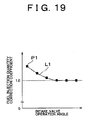
In the control apparatus, an amount of correction of the fuel injection quantity is
increased as the operation angle of the intake valve is decreased.
In the control apparatus according to another aspect of the invention, the controller
calculates a fuel injection quantity correction coefficient for reducing the variation in the air-fuel
ratio when the variation in the air-fuel ratio among the cylinders is detected, calculates a
relationship between the calculated fuel injection quantity correction coefficient and the
operation angle of the intake valve obtained upon calculation of the fuel injection quantity
correction coefficient, and updates the fuel injection quantity correction coefficient when the
operation angle of the intake valve is changed on the basis of the changed operation angle and
the calculated relationship.
In the control apparatus, the fuel injection quantity correction coefficient changes
relative to the operation angle of the intake valve such that an amount of correction of the
fuel injection quantity is increased as the operation angle is decreased.
The control apparatus as described above reduces the variation in the air-fuel ratio
among the cylinders by correcting the fuel injection quantity on the basis of the operation
angle of the intake valve. For example, when the air-fuel ratio of one cylinder varies on the
rich side, the fuel injection quantity supplied to the cylinder is decreased so as to reduce the
variation in the air-fuel ratio among the cylinders. Also, the smaller the operation angle of
the intake valve becomes, the greater the variation in the air-fuel ratio becomes among the
cylinders when the actual operation angle deviates from the target operation angle. In view
of this, the variation in the air-fuel ratio among the cylinders can be reduced by executing
correction, for example, increasing the fuel injection quantity as the operation angle of the
intake valve becomes smaller. This allows the variation in the air-fuel ratio among the
cylinders to be controlled more appropriately than when the fuel injection quantity is not
corrected on the basis of the operation angle of the intake valve. More specifically, when a
variation in the air-fuel ratio among the cylinders is detected, the control apparatus calculates
a fuel injection quantity correction coefficient for reducing such variation, and also calculates
a relationship between the calculated fuel injection quantity correction coefficient and the
operation angle of the intake valve upon calculation of the fuel injection quantity correction
coefficient. When the operation angle of the intake valve has changed, the control apparatus
then updates the fuel injection quantity correction coefficient on the basis of the changed
operation angle of the intake valve and the calculated relationship. The relationship between
the fuel injection quantity correction coefficient and the operation angle of the intake valve
can be represented by a relation formula or a map, for example.
According to another aspect of the invention, a control apparatus for a multi-cylinder
internal combustion engine including a plurality of cylinders is provided with a controller that
corrects a coefficient for an air-fuel ratio feedback control to a predetermined coefficient on
the basis of an operation angle of an intake valve of each of the cylinders, wherein a number
of sensors provided in the internal combustion engine for detecting an air-fuel ratio or an
oxygen concentration is smaller than a number of the cylinders of the internal combustion
engine.
In the control apparatus, the coefficient for the air-fuel ratio feedback control is
corrected to the predetermined coefficient such that a target air-fuel ratio is increased as the
operation angle of the intake valve is decreased.
According to another aspect of the invention, a control apparatus for a multi-cylinder
internal combustion engine including a plurality of cylinders is provided with a controller that
corrects a target air-fuel ratio on the basis of an operation angle of an intake valve of each of
the cylinders, wherein a number of sensors provided in the internal combustion engine for
detecting an air-fuel ratio or an oxygen concentration is smaller than a number of each of the
cylinders of the internal combustion engine.
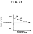
In the control apparatus, the target air-fuel ratio is corrected such that an amount for
correcting the target air-fuel ratio is increased as the operation angle of the intake valve is
decreased.
According to another aspect of the invention, the controller calculates the target air-fuel
ratio when a variation in the air-fuel ratio among the cylinders is detected, calculates a
relationship between the target air-fuel ratio and the operation angle of the intake valve on the
basis of the calculated target air-fuel ratio and the operation angle of the intake valve
obtained upon detection of the variation in the air-fuel ratio; and updates the target air-fuel
ratio when the operation angle of the intake valve is changed on the basis of the changed
operation angle of the intake valve and the calculated relationship between the target air-fuel
ratio and the operation angle of the intake valve of the cylinder.
The control apparatus of the invention corrects a predetermined coefficient relating to
an air-fuel ratio feedback control on the basis of the operation angle of the intake valve.
More specifically, the control apparatus corrects the target air-fuel ratio on the basis of the
operation angle of the intake valve. For example, in the event that the overall air-fuel ratio
shifts over to the rich side as a result of the target air-fuel ratio not being set appropriately due
to the fact that the sensor is not sufficiently exposed to the gas, the control apparatus then
corrects the target air-fuel ratio so as to shift the overall air-fuel ratio toward the lean side.
Also, when the actual operation angle of the intake valve deviates from the target operation
angle, the target air-fuel ratio that is set on the basis of a value output by the sensor is likely
to largely deviate from the appropriate target air-fuel ratio as the operation angle of the intake
valve becomes smaller. In view of this fact, for example, the correction amount for the target
air-fuel ratio is increased as the operation angle of the intake valve becomes smaller. This
allows the value of the target air-fuel ratio to be made more appropriate than when the target
air-fuel ratio is not corrected on the basis of the operation angle of the intake valve. That is,
the control apparatus is capable of executing appropriate air-fuel ratio feedback control even
when a sensor is not sufficiently exposed to the exhaust gas, i.e., even when a target air-fuel
ratio calculated from a value output by a sensor is not an appropriate target air-fuel ratio.
More specifically, when a variation in the air-fuel ratio among the cylinders is detected, the
control apparatus calculates a target air-fuel ratio (corrects it to an appropriate target air-fuel
ratio), and also calculates a relationship between that target air-fuel ratio and the operation
angle of the intake valve obtained at that time. When the operation angle of the intake valve
changes, the control apparatus then calculates the appropriate target air-fuel ratio on the basis
of the changed operation angle of the intake valve and the calculated relationship. The
relationship between the target air-fuel ratio and the operation angle of the intake valve can
be represented by a relational expression or a map, for example.
In the control apparatus, the controller reduces a variation in the air-fuel ratio among
the cylinders by correcting a fuel injection quantity of each of the cylinders independently
when an amount of correction of the calculated fuel injection quantity is smaller than a
predetermined value, and guards the amount for correcting the calculated fuel injection
quantity, corrects the target air-fuel ratio, and uniformly corrects each of the fuel injection
quantity of all the cylinders on the basis of the corrected target air-fuel ratio when an amount
of correction of the calculated fuel injection quantity is larger than the predetermined value.
In view of the possibility that a large correction amount for the fuel injection quantity
might result in a variation in torque, the control apparatus of the invention minimizes the
variation in the air-fuel ratio between cylinders by individually correcting the fuel injection
quantity in each of the cylinders when a calculated correction amount for the fuel injection
quantity is small, and guards the calculated correction amount for the fuel injection quantity
with a predetermined value when the correction amount for the fuel injection quantity is
large. At the same time, the control apparatus also corrects the target air-fuel ratio and then
uniformly corrects the fuel injection quantity of all of the cylinders on the basis of that target
air-fuel ratio. Accordingly the air-fuel ratio can be appropriately controlled while minimizing
the variation in torque.
BRIEF DESCRIPTION OF THE DRAWINGS
The invention will be described in conjunction with the following drawings, in which
like reference numerals refer to similar elements, and wherein:
DETAILED DESCRIPTION OF PREFERRED EMBODIMENTS
Hereinafter embodiments of the invention will be described with reference to the
attached drawings.
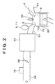
Figs. 1 through 3, which illustrate an embodiment of the invention for controlling a
first type of an internal combustion engine 1, show an intake valve 2, an exhaust valve 3, a
cam 4 for opening and closing the intake valve 2, a cam 5 for opening and closing the exhaust
valve 3, a cam shaft 6 which supports the cam 4, and a cam shaft 7 which supports the cam 5.
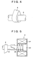
As shown in Fig. 4, the cam profile of the cam 4 according to this exemplary embodiment is
modified in the direction along the central axis of the cam shaft, i.e., the left end of the nose
of the first cam 4 in the figure is higher than the right end thereof. This feature may be
utilized to change the valve lift amount of the intake valve 2 depending on the contact
between the valve lifter and one end of the cam 4. That is, when the valve lifter contacts the
right end of the cam 4, the valve lift amount will become smaller than the valve lift amount
obtained when the valve lifter contacts the left end of the cam 4.
Figs. 1 through 3 also show a combustion chamber 8 formed in a cylinder and a valve
lift amount changing device 9 for shifting the cam 4 in the direction along the central axis of
the cam shaft with respect to the intake valve 2 to change the valve lift amount. That is,
operating the valve lift amount changing device 9 brings the left or right end (in Fig. 4) of the
cam 4 into contact with the valve lifter selectively. Changing the valve lift amount of the
intake valve 2 by the valve lift amount changing device 9 consequentially changes the open
area of the intake valve 2. The intake valve 2 according to this exemplary embodiment is
structured such that the open area of the intake valve 2 increases as the valve lift amount
increases. Figs. 1 through 3 also show a driver 10 for driving the valve lift amount changing
device 9 and an opening/closing timing shift device 11 for shifting the opening/closing timing
of the intake valve 2 regardless of a change in the open period thereof. That is, operation of
the opening/closing timing shift device 11 enables the opening/closing timing of the intake
valve 2 to be shifted to the advance side or the retard side. The figures also show an oil
control valve 12 for controlling an oil pressure for operating the opening/closing timing shift
device 11. Both the valve lift amount changing device 9 and the opening/closing timing shift
device 11 are included in the variable valve train in this exemplary embodiment.
Figs. 1 through 3 also show a crank shaft 13, an oil pan 14, a fuel injection valve 15, a
first sensor 16 for detecting both a valve lift amount and an opening/closing timing shift
amount of the intake valve 2, a second sensor 17 for detecting an engine speed, an intake pipe
pressure sensor 18 for detecting a pressure within an intake pipe that supplies intake air to the
cylinder, an airflow meter 19, a coolant temperature sensor 20 for detecting a temperature of
a coolant in the internal combustion engine 1, an intake air temperature sensor 21 for
detecting a temperature within the intake pipe for intake air to be supplied to the cylinder, an
ECU (electronic control unit) 22, a cylinder 50, intake pipes 51 and 52, a surge tank 53, an
exhaust pipe 54, a spark plug 55, a throttle valve 56, the opening amount of which changes
regardless of the accelerator pedal operation amount, and an air-fuel ratio sensor 57 for
detecting an exhaust gas air-fuel ratio.
Fig. 5 shows a magnetic body 30 connected to the cam shaft 6, a coil 31 for urging the
magnetic body 30 to the left, and a compression spring 32 for urging the magnetic body 30 to
the right. As the amount of current passing through the coil 31 increases, the amount by
which the cam 4 and the cam shaft 6 shift to the left increases and the valve lift amount of the
intake valve 2 decreases.
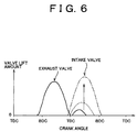
As shown in Fig. 6, the valve lift amount of the intake valve 2 increases as the amount
of current passing through the coil 31 decreases (solid line → broken line → chain line).
Further in this exemplary embodiment, the closed period of the intake valve 2 also changes as
the valve lift amount changing device 9 is operated. That is, the operation angle of the intake
valve 2 also changes. More specifically, the operation angle of the intake valve 2 increases as
the valve lift amount of the intake valve 2 increases (solid line → broken line → chain line).
Moreover in this embodiment, the timing at which the valve lift amount of the intake valve 2
is at its peak also changes as the valve lift amount changing device 9 is operated. More
specifically, the timing at which the valve lift amount of the intake valve 2 is at its peak is
retarded as the valve lift amount of the intake valve 2 increases (solid line → broken line →
chain line).
Fig. 7 shows an advance side oil passage 40 for shifting the opening/closing timing of
the intake valve 2 to the advance side, a retard side oil passage 41 for shifting the
opening/closing timing of the intake valve 2 to the retard side, and an oil pump 42. The
opening/closing timing of the intake valve 2 shifts to the advance side as the oil pressure
within the advance side oil passage 40 increases. That is, the rotation phase of the cam shaft
6 is advanced with respect to the crank shaft 13. Conversely, the opening/closing timing of
the intake valve 2 shifts to the retard side as the oil pressure within the retard side oil passage
41 increases. That is, the rotation phase of the cam shaft 6 is retarded with respect to the
crank shaft 13.
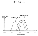
As shown in Fig. 8, the opening/closing timing of the intake valve 2 shifts to the
advance side as the oil pressure within the advance side oil passage 40 increases (solid line →
broken line → chain line). At this time, the open period of the intake valve 2 does not
change, i.e., the length of the period during which the intake valve 2 is open does not change.
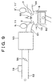
In Fig. 9, reference numerals that are the same as those in Figs. 1 through 8 represent
the same or like parts as those shown in Figs. 1 through 8. In this embodiment for controlling
a second type of internal combustion engine, the cam for driving the exhaust valve has
generally the same configuration as the cam 4 shown in Fig. 4. Fig. 9 also shows a valve lift
amount changing device 9' for shifting the cam for driving the exhaust valve in the direction
along the central axis of the cam shaft with respect to the exhaust valve 3 to change the valve
lift amount of the exhaust valve 3. This valve lift amount changing device 9' has generally
the same configuration as the valve lift amount changing device 9. Fig. 9 also shows an
opening/closing timing shift device 11' for shifting the opening/closing timing of the exhaust
valve 3 regardless of the open period of the exhaust valve 3. This opening/closing timing
shift device 11' has generally the same configuration as the opening/closing timing shift
device 11.
In Fig. 10, which illustrates an embodiment for controlling a third type of internal
combustion engine 2, reference numerals that are the same as those in Figs. 1 through 8
represent the same or like parts as those shown in Figs. 1 through 8. Fig. 10 also shows an
intake valve driving device 58 which is capable of driving individual intake valves 2 (refer to
Fig. 3) independently, e.g., an electromagnetic driving type intake valve driving device, and
an exhaust valve driving device 58' which is capable of driving individual exhaust valves 3
(refer to Fig. 3) independently, e.g., an electromagnetic driving type exhaust valve driving
device.
In modifications of the foregoing exemplary embodiments, the throttle valve 56 may
be eliminated.
In the foregoing exemplary embodiments and modifications thereof, when the air-fuel
ratio of a cylinder among a plurality of cylinders Nos. 1 through 4, is calculated based on a
value output from the air-fuel ratio sensor 57 and the valve lift amount of the intake valve 2
and/or exhaust valve 3 of each cylinder is controlled, a variation in the air-fuel ratio between
cylinders is able to be reduced. If variation in the fuel injection quantity exists between
cylinders, however, even if the variation in the air-fuel ratio between cylinders is reduced, a
variation in torque between cylinders is generated, resulting in a pulsation (torque variation).
Therefore, according to the first and second exemplary embodiments and modifications
thereof, control such as that to be described later is performed to both reduce variation in the
air-fuel ratio between cylinders and reduce variation in the torque between cylinders.
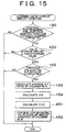
A routine according to a method for learning fuel injection quantity variation
according to the foregoing embodiments and modification thereof as shown in Fig. 11 is
performed at predetermined intervals. As shown in the figure, when this routine starts, it is
determined in Step 100 whether the operation angle of the intake valve 2 is at its maximum,
as illustrated by the chain line in Fig. 6, for example. When the above determination is
"NO", i.e., when the operation angle of the intake valve 2 is relatively small, such that the
open area of the intake valve 2 is relatively small, the intake air amount to be introduced into
the cylinder 50 is determined based on the open area of the intake valve 2. In the event that
variation in the operation angle of the intake valve 2 among cylinders exists temporarily, the
intake air amount varies among cylinders and it is determined that learning variation in the
fuel injection quantity is not possible and the routine ends. Meanwhile, when the
determination in Step 100 is "YES", then the intake air amount to be introduced into the
cylinder 50 is determined based on the opening amount of the throttle valve 56 or the cross-sectional
area of the portion of the intake pipes 51 and 52 having the smallest internal
circumference. Even if variation in the operation angle of the intake valve 2 exists among
cylinders, it is determined that the intake air amount does not vary among cylinders, and the
process proceeds to Step 101.
In Step 101, it is determined whether it is time to calculate the exhaust gas air-fuel
ratio of the specified cylinder No. N among a plurality of cylinders Nos. 1 through 4. When
the determination is "NO", the routine ends. When the determination is "YES", the process
proceeds to Step 102. In Step 102, the exhaust gas air-fuel ratio of the cylinder No. N, for
example, is detected for several cycles and the mean air-fuel ratio thereof is calculated. This
mean air-fuel ratio calculation is performed for all of the cylinders Nos. 1 through 4. Next, in
Step 103, the variation ΔQn in the fuel injection quantity among the cylinders is calculated
using the air-fuel ratio of each of the cylinders Nos. 1 through 4 calculated in Step 102 on the
assumption that the intake air amounts to be introduced into each of the cylinders Nos. 1
through 4 are all the same.
Next in Step 104, a variation rate Qrate-n of the fuel injection quantity is calculated
based on the variation ΔQn in the fuel injection quantity between the cylinders calculated in
Step 103. Then in Step 105, the fuel injection quantity of each of the cylinders Nos. 1
through 4 is corrected so as to eliminate or reduce the variation in the fuel injection quantity
among the cylinders.
In the aforementioned case, when it is determined in Step 100 that the operation angle
of the intake valve 2 is set to the maximum operation angle, the exhaust gas air-fuel ratio of
that cylinder is then calculated in Step 102. That is, when it is determined in Step 100 that
the operation angle of the intake valve 2 is set such that the intake air amount introduced into
the cylinder is not limited by the operation angle of the intake valve 2, the exhaust gas air-fuel
ratio of that cylinder is then calculated in Step 102. More specifically, when it is
determined in Step 100 that the operation angle of the intake valve 2 is set such that the
intake air amount introduced into the cylinder is limited by the opening amount of the throttle
valve 56, and not limited by the operation angle of the intake valve 2, the exhaust gas air-fuel
ratio of that cylinder is calculated in Step 102. In other words, for the exhaust gas air-fuel
ratio of a cylinder to be calculated in Step 102, the operation angle of the intake valve 2 is set,
in a step which is not shown, such that the intake air amount introduced into that cylinder is
limited by the opening amount of the throttle valve 56, and is not limited by the operation
angle of the intake valve 2. That is, by making the opening amount of the throttle valve 56
when the exhaust gas air-fuel ratio of the first cylinder No. 1 is calculated and the opening
amount of the throttle valve 56 when the exhaust gas air-fuel ratios of the other cylinders
Nos. 2 through 4 are calculated substantially the same, it is possible to make the intake air
amount to be introduced into the first cylinder No. 1 when the exhaust gas air-fuel ratio
thereof is calculated and the intake air amount introduced into the other cylinders Nos. 2
through 4 when the exhaust gas air-fuel ratios thereof are calculated the same.
Further, according to the foregoing embodiments, when it is determined in Step 100
that the intake air amount to be introduced into the cylinder No. 1 upon calculation of the
exhaust gas air-fuel ratio is the same as that to be introduced into the other cylinders Nos. 2
through 4 upon calculation of the exhaust gas air-fuel ratios, variation in the fuel injection
quantity among the cylinders is minimized in Step 105 by the exhaust gas air-fuel ratio. That
is, after making the intake air amount in all of the cylinders the same, the fuel injection
quantity is corrected such that the exhaust gas air-fuel ratios in all of the cylinders are the
same. This makes it possible to reduce both the variation in the air-fuel ratio among
cylinders and the variation in the torque among cylinders.
In other words, according to the embodiments, when it is determined in Step 100 that
the valve opening characteristics of the intake valve 2 are set such that the intake air amount
to be introduced into the cylinder is limited by the opening amount of the throttle valve 56,
and not limited by the valve opening characteristics of the intake valve 2, the exhaust gas air-fuel
ratio of that cylinder is then calculated in Step 102. That is, for the exhaust gas air-fuel
ratio of a cylinder to be calculated in Step 102, the valve opening characteristics of the intake
valve 2 are set, in a step which is not shown, such that the intake air amount to be introduced
into that cylinder is limited by the opening amount of the throttle valve 56, and is not limited
by the valve opening characteristics of the intake valve 2.
Also according to modifications of the aforementioned embodiments in which the
throttle valve 56 is not provided, when it is determined in Step 100 that the operation angle of
the intake valve 2 is set to the maximum operation angle, the exhaust gas air-fuel ratio of that
cylinder is calculated in Step 102. That is, when it is determined in Step 100 that the
operation angle of the intake valve 2 is set so as not to limit the intake air amount to be
introduced into the cylinder, the exhaust gas air-fuel ratio of that cylinder is then calculated in
Step 102. More specifically, when it is determined in Step 100 that the operation angle of the
intake valve 2 is set such that the intake air amount to be introduced into the cylinder is
limited by the cross-sectional area of a portion of the intake pipes 51 and 52 having the
smallest internal circumference, and is not limited by the operation angle of the intake valve
2, the exhaust gas air-fuel ratio of that cylinder is then calculated in Step 102. In other words,
for the exhaust gas air-fuel ratio of a cylinder to be calculated in Step 102, the operation angle
of the intake valve 2 is set, in a step (not shown) to the maximum operation angle such that
the intake air amount to be introduced into the cylinder is limited by the cross-sectional area
of a portion of the intake pipes 51 and 52 having the smallest internal circumference, and not
limited by the operation angle of the intake valve 2.
In other words, according to the above-described modifications, when it is determined
in Step 100 that the valve opening characteristics of the intake valve 2 are set such that the
intake air amount to be introduced into the cylinder is limited by the cross-sectional area of a
portion of the intake pipes 51 and 52 having the smallest internal circumference, and not
limited by the valve opening characteristics of the intake valve 2, the exhaust gas air-fuel
ratio of that cylinder is calculated in Step 102. That is, for the exhaust gas air-fuel ratio of a
cylinder to be calculated in Step 102, the valve opening characteristics of the intake valve 2
are set, in a step (not shown) such that the intake air amount to be introduced into that
cylinder is limited by the cross-sectional area of a portion of the intake pipes 51 and 52
having the smallest internal circumference, and is not limited by the valve opening
characteristics of the intake valve 2.
Also according to the exemplary embodiments and modifications thereof, the
variation among cylinders is able to be reduced based on the operation angle of the intake
valve. More specifically, the variation in the fuel injection quantity among cylinders can be
reduced by the operation angle of the intake valve. Even more specifically, when it is
determined in Step 100 in Fig. 11 that the operation angle of the intake valve assumes a
maximum value, the variation in the fuel injection quantity between the cylinders is
minimized in Step 105. Therefore, when it is possible to change the operation angle of the
intake valve, it is possible to control the variation in the air-fuel ratio between the cylinders
more appropriately than when the variation between cylinders is not controlled by the
operation angle of the intake valve. In other words, it is possible to appropriately control the
variation in the air-fuel ratio among the cylinders.
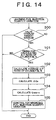
A routine according to the method for learning intake valve operation angle variation,
according to the embodiment for controlling the third type of the internal combustion engine
and a modification thereof shown in Fig. 12 is executed at predetermined intervals, just as the
routine shown in Fig. 11. In Fig. 12, when this routine starts, it is first determined in Step
150 whether the correction control in Step 105 in Fig. 11 has been completed. If the
correction of the fuel injection quantity for all of the cylinders is not yet complete, then it is
determined that the variation in the operation angle of the intake valve 2 among the cylinders
can not be reduced and the routine ends. If the correction of the fuel injection quantity for all
of the cylinders is complete, then the process proceeds to Step 151. In Step 151, it is
determined whether the operation angle of the intake valve 2 is equal to or less than a
predetermined threshold value. That is, it is determined whether the operation angle of the
intake valve 2 is set to a relatively small value such that the intake air amount to be
introduced into the cylinder is limited by the operation angle of the intake valve 2, and not
limited by the opening amount of the throttle valve 56. If the determination is "NO", the
routine ends. If the determination is "YES", the process proceeds to Step 152.
In Step 152, it is determined whether it is time to calculate the exhaust gas air-fuel
ratio of the specified cylinder, for example, cylinder No. N, among the plurality of cylinders
Nos. 1 through 4. If the determination is "NO", the routine ends. If the determination is,
"YES", the process proceeds to Step 153. In Step 153, the exhaust gas air-fuel ratio of the
cylinder No. N is detected for several cycles and the mean air-fuel ratio thereof is calculated.
This mean air-fuel ratio calculation is performed for all of the cylinders Nos. 1 through 4.
Next in Step 154, the variation ΔQ in the intake air amount among the cylinders is calculated
using the air-fuel ratio of each of the cylinders Nos. 1 through 4 calculated in Step 153 on the
assumption that the fuel injection quantity of each of the cylinders Nos. 1 through 4 is the
same.
Next in Step 155, the variation ΔAng in the operation angle of the intake valve 2 of a
specified cylinder, for example, cylinder No. N, is calculated based on the variation ΔQ in the
intake air amount among the cylinders calculated in Step 154. This calculation of the
variation ΔAng in the operation angle of the intake valve 2 is performed for all of the
cylinders Nos. 1 through 4. Next in Step 156, the intake valve driving device 58 corrects the
operation angle of the intake valve 2 of each of the cylinders Nos. 1 through 4 such that the
variation in the operation angle of the intake valves 2 among the cylinders is reduced, i.e.,
such that the variation in the intake air amount among the cylinders is reduced.
According to the embodiment for controlling the third type of the internal combustion
engine, after reducing the variation in the fuel injection quantity between the cylinders in
Step 105 in Fig. 11, when it is determined in Step 151 that the valve opening characteristics
of the intake valve 2 are set so that the intake air amount to be introduced into the cylinder is
limited by the valve opening characteristics of the intake valve 2, and not limited by the
opening amount of the throttle valve 56, the process proceeds to Step 153. In Step 153, the
exhaust gas air-fuel ratio of that cylinder is calculated and then in Step 156 the variation in
the valve opening characteristics of the intake valve 2 among cylinders is reduced by that
exhaust gas air-fuel ratio. That is, after reducing the variation in the fuel injection quantity
among the cylinders, the valve opening characteristics of the intake valve 2 of each of the
cylinders Nos. 1 through 4 are changed such that the exhaust gas air-fuel ratio of the cylinder
No. 1 and the exhaust gas air-fuel ratios of the other cylinders Nos. 2 through 4 are the same.
Therefore, even if there is variation in the fuel intake quantity among the cylinders, no
variation in torque among cylinders is generated and variation in the valve opening
characteristics of the intake valve 2 among the cylinders can be reduced.
Also, according to a modification of the embodiment, after reducing the variation in
the fuel injection quantity among the cylinders in Step 105 in Fig. 11, when it is determined
in Step 151 that the valve opening characteristics of the intake valve 2 are set so that the
intake air amount to be introduced into the cylinder is limited by the valve opening
characteristics of the intake valve 2, and not limited by the cross-sectional area of the portion
of the intake pipes 51 and 52 having the smallest internal circumference, the process proceeds
to Step 153. In Step 153, the exhaust gas air-fuel ratio of that cylinder is calculated and then
in Step 156, the variation in the valve opening characteristics of the intake valve 2 among
cylinders is reduced by that exhaust gas air-fuel ratio. That is, after reducing the variation in
the fuel injection quantity among the cylinders, the valve opening characteristics of the intake
valve 2 of each of the cylinders Nos. 1 through 4 are changed such that the exhaust gas air-fuel
ratio of the cylinder No. 1 and the exhaust gas air-fuel ratios of the other cylinders Nos. 2
through 4 are the same. Therefore, even if there is variation in the fuel intake quantity among
cylinders, no variation in torque among cylinders is generated and the variation in the valve
opening characteristics of the intake valves 2 among the cylinders can be reduced.
More specifically, according to the embodiment for controlling the third type of the
internal combustion engine and the modification thereof, after reducing the variation in the
fuel injection quantity among the cylinders in Step 105 in Fig. 11, when it is determined in
Step 151 that the operation angle of the intake valve 2 is set to a predetermined angle which
is smaller than the maximum operation angle, the process proceeds to Step 153. In Step 153,
the exhaust gas air-fuel ratio is calculated and then in Step 156, the variation in the operation
angle of the intake valve 2 among the cylinders is reduced by that exhaust gas air-fuel ratio.
That is, after reducing the variation in the fuel injection quantity among the cylinders, the
operation angle of the intake valve 2 of each of the cylinders Nos. 1 through 4 is changed
such that the exhaust gas air-fuel ratio of the cylinder No. 1 and the exhaust gas air-fuel ratios
of the other cylinders Nos. 2 through 4 are the same. Therefore, even if there is variation in
the fuel intake quantity among cylinders, no variation in torque among cylinders is generated
and the variation in the operation angle of the intake valve 2 among the cylinders can be
reduced.
According to the foregoing embodiment and the modification thereof, after reducing
the variation in the fuel injection quantity among the cylinders in Step 105 in Fig. 11, when it
is determined in Step 151 that the operation angle of the intake valve 2 is set to a
predetermined operation angle that is smaller than the maximum operation angle, the process
proceeds to Step 153. In Step 153, the exhaust gas air-fuel ratio is calculated and then in Step
156, the variation in the intake air amount among cylinders is reduced by that exhaust gas air-fuel
ratio. That is, after reducing the variation in the fuel injection quantity among the
cylinders, the operation angle of the intake valve 2 of each of the cylinders Nos. 1 through 4
is changed such that the exhaust gas air-fuel ratio of the cylinder No. 1 and the exhaust gas
air-fuel ratios of the other cylinders Nos. 2 through 4 are the same. Therefore, even if there is
variation in the fuel intake quantity among the cylinders, no variation in torque among
cylinders is generated and the variation in the intake air amount among the cylinders can be
reduced.
Also according to the embodiments for controlling the first to the third type of the
internal combustion engines and modifications thereof, a variation among cylinders is
reduced by the operation angle of the intake valve. More specifically, when it is determined
in Step 151 in Fig. 12 that the operation angle of the intake valve 2 is equal to or less than a
predetermined threshold value, the variation in the operation angle of the intake valve 2
among the cylinders is reduced in Step 156. Therefore, when it is possible to change the
operation angle of the intake valve, the variation in the air-fuel ratio among the cylinders can
be controlled more appropriately than when the variation in the operation angle of the intake
valve 2 among the cylinders is controlled irrespective of the aforementioned threshold value.
In other words, it is possible to appropriately control the variation in the air-fuel ratio among
the cylinders.
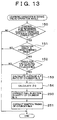
A routine according to the method for learning intake valve operation angle variation,
according to the embodiment for controlling the first and the second type of the internal
combustion engines and modifications thereof, shown in Fig. 13 is executed at predetermined
intervals, just as is the routine shown in Fig. 11. As shown in Fig. 13, when this routine
starts, it is first determined in Step 150 whether the control for reducing the variation in the
fuel injection quantity in Step 105 shown in Fig. 11 has been completed, just as in Fig. 12. If
the control is not yet complete, it is determined that the variation in the operation angle of the
intake valve 2 among the cylinders can not be reduced. Accordingly the routine ends. If the
correction of the fuel injection quantity for all of the cylinders is complete, the process
proceeds to Step 151. In Step 151, just as in Fig. 12, it is determined whether the operation
angle of the intake valve 2 is equal to or less than a predetermined threshold value. If the
determination is "NO", the routine ends. If the determination is "YES", the process proceeds
to Step 152.
In Step 152, it is determined whether it is time to calculate the exhaust gas air-fuel
ratio of the specified cylinder, for example, the cylinder No. N, among a plurality of cylinders
Nos. 1 through 4, just as in Fig. 12. If the determination is "NO", the routine ends. If the
determination is "YES", the process proceeds to Step 153. In Step 153, the exhaust gas air-fuel
ratio of the cylinder No. N, for example, is detected for several cycles and the mean air-fuel
ratio thereof is calculated, just as in Fig. 12. Next in Step 154, the variation ΔQ in the
intake air amount among the cylinders is calculated using the air-fuel ratio of each of the
cylinders Nos. 1 through 4 calculated in Step 153 on the assumption that the fuel injection
quantity in each of the cylinders Nos. 1 through 4 are all the same, also just as in Fig. 12.
Next in Step 250, the fuel injection quantity of each cylinder is corrected based on the
variation ΔQ in the intake air amount among the cylinders calculated in Step 154 such that
the torque of all of the cylinders Nos. 1 through 4 is the same. Then in Step 251, the ignition
timing of each cylinder is corrected based on the variation ΔQ in the intake air amount among
the cylinders calculated in Step 154 such that the torque of all of the cylinders Nos. 1 through
4 is the same. For example, the ignition timing in a cylinder in which the intake air amount is
relatively large is retarded during operation under high load of the engine, in which knocking
tends to occur.
According to the embodiment for controlling the first and second type of the internal
combustion engines, after reducing the variation in the fuel injection quantity among the
cylinders in Step 105 shown in Fig. 11, when it is determined in Step 151 shown in Fig. 13
that the valve opening characteristics of the intake valve 2 are set such that the intake air
amount to be introduced into the cylinder is limited by the valve opening characteristics of
the intake valve 2, and not limited by the opening amount of the throttle valve 56, the process
proceeds to Step 153. In Step 153, the exhaust gas air-fuel ratio of that cylinder is calculated
and then in Step 250 and Step 251, the fuel injection quantity and the ignition timing,
respectively, are corrected so as to reduce the variation in torque among cylinders.
According to the foregoing embodiments and modifications thereof, after reducing the
variation in the fuel injection quantity among the cylinders in Step 105 shown in Fig. 11,
when it is determined in Step 151 in Fig. 13 that the valve opening characteristics of the
intake valve 2 are set so that the intake air amount to be introduced into the cylinder is limited
by the valve opening characteristics of the intake valve 2, and not limited by the cross-sectional
area of the portion of the intake pipes 51 and 52 having the smallest internal
circumference, the process proceeds to Step 153. In Step 153, the exhaust gas air-fuel ratio
of that cylinder is calculated and then in Step 250 and Step 251 the fuel injection quantity and
ignition timing, respectively, are corrected so as to reduce the variation in torque among the
cylinders.
According to the embodiment for controlling the first to the third type of the internal
combustion engine and the modifications thereof, the variation among cylinders is controlled
based on the operation angle of the intake valve. More specifically, when it is determined in
Step 151 shown in Fig. 13 whether the operation angle of the intake valve 2 is equal to or less
than a predetermined threshold value, the variation in the air-fuel ratio among the cylinders is
controlled in Step 250. Therefore, when it is possible to change the operation angle of the
intake valve, the variation in the air-fuel ratio among the cylinders can be controlled more
appropriately than when the variation in the air-fuel ratio among the cylinders is controlled
irrespective of the aforementioned threshold value. In other words, it is possible to
appropriately control the variation in the air-fuel ratio among the cylinders.
Hereinafter, additional embodiments of a control apparatus for an internal combustion
engine according to the invention will be described. The configurations of these
embodiments are substantially the same as the configurations of each of the foregoing
embodiments. Also, configurations of modifications of these embodiments are substantially
the same as the configurations of the foregoing modifications of each of the embodiments.
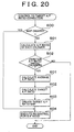
A routine according to the method for learning fuel injection quantity variation
according to the foregoing embodiments and modifications thereof as shown in Fig. 14 is
executed at predetermined intervals just as the routine shown in Fig. 11. Referring to Fig. 14,
when this routine starts, it is first determined in Step 300 whether a valve overlap amount of
the intake valve 2 and the exhaust valve 3 is minimum. When the determination is "NO",
i.e., when the valve overlap amount of the intake valve 2 and the exhaust valve 3 is relatively
large, the intake air amount to be introduced into the cylinder 50 is determined by the valve
overlap amount of the intake valve 2 and the exhaust valve 3. When there is temporary
variation in the valve overlap amount between the cylinders, a variation in the intake air
amount is generated and it is determined that variation in the fuel injection quantity cannot be
learned, and the routine ends. However, when the determination in Step 300 is "YES", the
intake air amount to be introduced into the cylinder 50 is determined by the opening amount
of the throttle valve 56 or the cross-sectional of the portion of the intake pipes 51 and 52
having the smallest internal circumference, because the blow back gas amount from the
cylinder 50 to the intake pipe 51 is small. Even when there is a variation in the valve overlap
amount of the intake valve 2 and the exhaust valve 3 among the cylinders, it is determined
that no variation in the intake air amount is generated between the cylinders, and the process
proceeds to Step 101.
In Step 101, it is determined whether it is time to calculate the exhaust gas air-fuel
ratio of the specified cylinder, for example, the cylinder No. N, among a plurality of cylinders
Nos. 1 through 4, just as was shown in Fig. 11. When the determination is "NO", the routine
ends. When the determination is "YES", the process proceeds to Step 102. In Step 102, the
exhaust gas air-fuel ratio of the cylinder No. N, for example, is detected for several cycles
and the mean air-fuel ratio thereof is calculated, just as was shown in Fig. 11. Next in Step
103, a variation ΔQn in the fuel injection quantity among the cylinders detected in Step 102 is
calculated using the air-fuel ratio of each of the cylinders Nos. 1 through 4, just as was shown
in Fig. 11.
Next in Step 104, a variation rate Qrate-n of the fuel injection quantity is calculated
based on the variation ΔQn in the fuel injection quantity among the cylinders calculated in
Step 103, just as was shown in Fig. 11. Then in Step 105, the fuel injection quantity of each
of the cylinders Nos. 1 through 4 is corrected so as to reduce the variation in the fuel injection
quantity among the cylinders, just as was shown in Fig. 11.
According to the embodiments, when it is determined in Step 300 that the valve
overlap amount of the intake valve 2 and the exhaust valve 3 is set to the minimum value, the
exhaust gas air-fuel ratio of that cylinder is then calculated in Step 102. That is, when it is
determined in Step 300 that the valve overlap amount of the intake valve 2 and the exhaust
valve 3 is set so as not to limit the intake air amount to be introduced into the cylinder, the
exhaust gas air-fuel ratio of that cylinder is then calculated in Step 102. More specifically,
when it is determined in Step 300 that the valve overlap amount of the intake valve 2 and the
exhaust valve 3 is set such that the intake air amount to be introduced into the cylinder is
limited by the opening amount of the throttle valve 56, and not limited by the valve overlap
amount, the exhaust gas air-fuel ratio of that cylinder is calculated in Step 102. In other
words, for the exhaust gas air-fuel ratio of a cylinder to be calculated in Step 102, the valve
overlap amount of the intake valve 2 and the exhaust valve 3 is set, in a step which is not
shown, such that the intake air amount to be introduced into that cylinder is limited by the
opening amount of the throttle valve 56, and not limited by the valve overlap amount of the
intake valve 2 and the exhaust valve 3. That is, by making the opening amount of the throttle
valve 56 when the exhaust gas air-fuel ratio of the first cylinder No. 1 is calculated and the
opening amount of the throttle valve 56 when the exhaust gas air-fuel ratios of the other
cylinders Nos. 2 through 4 are calculated substantially the same, it is possible to make the
intake air amount to be introduced into the first cylinder No. 1 upon calculation of the
exhaust gas air-fuel ratio thereof and the intake air amount to be introduced into the other
cylinders Nos. 2 through 4 upon calculation of the exhaust gas air-fuel ratios thereof the
same.
Further, in the embodiments, when it is determined in Step 300 that the intake air
amount to be introduced into the cylinder No. 1 when the exhaust gas air-fuel ratio thereof is
calculated and the intake air amount to be introduced into the other cylinders Nos. 2 through
4 when the exhaust gas air-fuel ratios thereof are calculated are the same, the variation in the
fuel injection quantity among the cylinders is reduced in Step 105 based on the exhaust gas
air-fuel ratio. That is, after making the intake air amount in all of the cylinders the same, the
fuel injection quantity is corrected such that the exhaust gas air-fuel ratios in all of the
cylinders are the same. This allows both the variation in the air-fuel ratio among cylinders, as
well as the variation in the torque among cylinders, to be reduced.
In other words, according to the embodiments, when it is determined in Step 300 that
the valve opening characteristics of the intake valve 2 and the exhaust valve 3 are set such
that the intake air amount to be introduced into the cylinder is limited by the opening amount
of the throttle valve 56, and not limited by the valve opening characteristics of the intake
valve 2 and the exhaust valve 3, the exhaust gas air-fuel ratio of that cylinder is then
calculated in Step 102. That is, for the exhaust gas air-fuel ratio of a cylinder to be calculated
in Step 102, the valve opening characteristics of the intake valve 2 and the exhaust valve 3
are set, in a step which is not shown, such that the intake air amount to be introduced into that
cylinder is limited by the opening amount of the throttle valve 56, and not limited by the
valve opening characteristics of the intake valve 2 and the exhaust valve 3.
Also, according to modifications of the embodiments in which the throttle valve 56 is
not provided, just as in the embodiments, when it is determined in Step 300 that the valve
overlap amount of the intake valve 2 and the exhaust valve 3 is set to the minimum value, the
exhaust gas air-fuel ratio of that cylinder is calculated in Step 102. That is, when it is
determined in Step 300 that the valve overlap amount of the intake valve 2 and the exhaust
valve 3 is set so as not to limit the intake air amount to be introduced into the cylinder, the
exhaust gas air-fuel ratio of that cylinder is then calculated in Step 102. More specifically,
when it is determined in Step 300 that the valve overlap amount of the intake valve 2 and the
exhaust valve 3 is set such that the intake air amount to be introduced into the cylinder is
limited by the cross-sectional area of a portion of the intake pipes 51 and 52 having the
smallest internal circumference, and not limited by the valve overlap amount of the intake
valve 2 and the exhaust valve 3, the exhaust gas air-fuel ratio of that cylinder is then
calculated in Step 102. In other words, for the exhaust gas air-fuel ratio of a cylinder to be
calculated in Step 102, the valve overlap amount of the intake valve 2 and the exhaust valve 3
are set, in a step which is not shown, to the minimum value such that the intake air amount to
be introduced into the cylinder is limited by the cross-sectional area of a portion of the intake
pipes 51 and 52 having the smallest internal circumference, and not limited by the valve
overlap amount of the intake valve 2 and the exhaust valve 3.
In other words, according to modifications of the embodiments, when it is determined
in Step 300 that the valve opening characteristics of the intake valve 2 and the exhaust valve
3 are set such that the intake air amount to be introduced into the cylinder is limited by the
cross-sectional area of a portion of the intake pipes 51 and 52 having the smallest internal
circumference, and not limited by the valve opening characteristics of the intake valve 2 and
the exhaust valve 3, the exhaust gas air-fuel ratio of that cylinder is then calculated in Step
102. That is, for the exhaust gas air-fuel ratio of a cylinder to be calculated in Step 102, the
valve opening characteristics of the intake valve 2 and the exhaust valve 3 are set, in a step
which is not shown, such that the intake air amount to be introduced into that cylinder is
limited by the cross-sectional area of a portion of the intake pipes 51 and 52 having the
smallest internal circumference, and not limited by the valve opening characteristics of the
intake valve 2 and the exhaust valve 3.
Also, according to the foregoing embodiments and modifications, the variation among
cylinders is able to be reduced based on the valve overlap amount of the intake valve 2 and
the exhaust valve 3. More specifically, the variation in the fuel injection quantity among
cylinders can be reduced based on the valve overlap amount of the intake valve 2 and the
exhaust valve 3. Even more specifically, when it is determined in Step 300 in Fig. 14 that the
valve overlap amount of the intake valve 2 and the exhaust valve 3 is set to the minimum
value, the variation in the fuel injection quantity among the cylinders is reduced in Step 105.
Therefore, when it is possible to change the valve overlap amount of the intake valve and the
exhaust valve, the variation in the air-fuel ratio among the cylinders can be controlled more
appropriately than when the variation among cylinders is not reduced based on the valve
overlap amount of the intake valve and the exhaust valve. In other words, it is possible to
appropriately control the variation in the air-fuel ratio among the cylinders.
A routine according to the method for learning valve overlap amount variation,
according to another embodiment and a modification thereof, in Fig. 15 is executed at
predetermined intervals, just as the routine shown in Fig. 14. Referring to Fig. 15, when this
routine starts, it is first determined in Step 150 whether the control in Step 105 in Fig. 14 has
been completed. If the correction of the fuel injection quantity for all of the cylinders is not
yet complete, it is determined that the variation in the valve overlap amount of the intake
valve 2 and the exhaust valve 3 among the cylinders can not be reduced and the routine ends.
If the correction of the fuel injection quantity for all of the cylinders is complete, then the
process proceeds to Step 450. In Step 450, it is determined whether the valve overlap amount
of the intake valve 2 and the exhaust valve 3 is equal to or greater than a predetermined
threshold value. That is, it is determined whether the valve overlap amount of the intake
valve 2 and the exhaust valve 3 is set to a relatively large value such that the intake air
amount to be introduced into the cylinder is limited by the valve overlap amount of the intake
valve 2 and the exhaust valve 3, and not limited by the opening amount of the throttle valve
56. If the determination in step 450 is "NO", the routine ends. If the determination is "YES",
the process proceeds to Step 152.
In Step 152, it is determined whether it is time to calculate the exhaust gas air-fuel
ratio of the specified cylinder, for example, the cylinder No. N, among a plurality of cylinders
Nos. 1 through 4, just as was shown in Fig. 12. If the determination is "NO", the routine
ends. If the determination is "YES", the process proceeds to Step 153. In Step 153, the
exhaust gas air-fuel ratio of the cylinder No. N, for example, is detected for several cycles
and the mean air-fuel ratio thereof is calculated, just as in Fig. 12. Next, in Step 154, the
variation ΔQ in the intake air amount among the cylinders is calculated using the air-fuel
ratio of each of the cylinders Nos. 1 through 4 calculated in Step 153 on the assumption that
the fuel injection quantities of all of the cylinders Nos. 1 through 4 are the same.
Next in Step 451, a variation ΔVo in the valve overlap amount of the intake valve 2
and the exhaust valve 3 of the specified cylinder, for example, cylinder No. N, is calculated
based on the variation ΔQ in the intake air amount among the cylinders calculated in Step
154. This calculation of the variation ΔVo in the valve overlap amounts of the intake valves
2 and the exhaust valves 3 is performed for all of the cylinders Nos. 1 through 4. Next in
Step 452, the intake valve driving device 58 corrects the opening timing of the intake valves
2 of each of the cylinders Nos. 1 through 4, while the intake valve driving device 58' corrects
the closing timing of the exhaust valves 3 of each of the cylinders Nos. 1 through 4, such that
the variation in the valve overlap amounts of the intake valves 2 and exhaust valves 3 among
the cylinders is reduced, i.e., such that the variation in the intake air amount among the
cylinders is reduced.
According to the embodiment, after reducing the variation in the fuel injection
quantity among the cylinders in Step 105 in Fig. 14, when it is determined in Step 450 in Fig.
15 that the valve opening characteristics of the intake valve 2 and the exhaust valve 3 are set
so that the intake air amount to be introduced into the cylinder is limited by the valve opening
characteristics of the intake valve 2 and the exhaust valve 3, and not limited by the opening
amount of the throttle valve 56, the process proceeds to Step 153. In Step 153, the exhaust
gas air-fuel ratio of that cylinder is calculated and then in Step 452, the variation in the valve
opening characteristics of the intake valve 2 and the exhaust valve 3 among cylinders is
reduced based on that exhaust gas air-fuel ratio. That is, after reducing the variation in the
fuel injection quantity among the cylinders, the valve opening characteristics of the intake
valves 2 and exhaust valves 3 of each of the cylinders Nos. 1 through 4 are changed such that
the exhaust gas air-fuel ratio of the cylinder No. 1 and the exhaust gas air-fuel ratios of the
other cylinders Nos. 2 through 4 are the same. Therefore, even if there is variation in the fuel
intake quantity among cylinders, no variation in torque among cylinders is generated and the
variation in the valve opening characteristics of the intake valves 2 and exhaust valves among
the cylinders can be reduced.
Also according to a modification of the embodiment, after reducing the variation in
the fuel injection quantity among the cylinders in Step 105 in Fig. 14, when it is determined
in Step 450 in Fig. 15 that the valve opening characteristics of the intake valve 2 and the
exhaust valve 3 are set so that the intake air amount to be introduced into the cylinder is
limited by the valve opening characteristics of the intake valve 2 and the exhaust valve 3, and
not limited by the cross-sectional area of the portion of the intake pipes 51 and 52 having the
smallest internal circumference, the process proceeds to Step 153. In Step 153, the exhaust
gas air-fuel ratio of that cylinder is calculated and then in Step 452, the variation in the valve
opening characteristics of the intake valve 2 and exhaust valve 3 among cylinders is reduced
based on that exhaust gas air-fuel ratio. That is, after reducing the variation in the fuel
injection quantity among the cylinders, the valve opening characteristics of the intake valves
2 and exhaust valves 3 of each of the cylinders Nos. 1 through 4 are changed such that the
exhaust gas air-fuel ratio of the cylinder No. 1 and the exhaust gas air-fuel ratios of the other
cylinders Nos. 2 through 4 are the same. Therefore, even if there is variation in the fuel
intake quantity among cylinders, no variation in torque among cylinders is generated and the
variation in the valve opening characteristics of the intake valves 2 and exhaust valves 3
among the cylinders can be reduced.
More specifically, according to the embodiment and the modification thereof, after
reducing the variation in the fuel injection quantity among the cylinders in Step 105 in Fig.
14, when it is determined in Step 450 in Fig. 15 that the valve overlap amount of the intake
valve 2 and the exhaust valve 3 is set to the minimum value, the process proceeds to Step
153. In Step 153, the exhaust gas air-fuel ratio is calculated and then in Step 451, the
variation in the valve overlap amount of the intake valve 2 and the exhaust valve 3 among
cylinders is reduced based on that exhaust gas air-fuel ratio. That is, after reducing the
variation in the fuel injection quantity among the cylinders, the valve overlap amount of the
intake valve 2 and the exhaust valve 3 of each of the cylinders Nos. 1 through 4 is changed
such that the exhaust gas air-fuel ratio of the cylinder No. 1 and the exhaust gas air-fuel ratios
of the other cylinders Nos. 2 through 4 are the same. Therefore, even if there is variation in
the fuel intake quantity among cylinders, no variation in torque among cylinders is generated
and the variation in the valve overlap amount of the intake valve 2 and the exhaust valve 3
among the cylinders can be reduced.
In other words, according to the embodiment and the modification thereof, after
reducing the variation in the fuel injection quantity among the cylinders in Step 105 in Fig.
14, when it is determined in Step 450 in Fig. 15 that the valve overlap amount of the intake
valve 2 and the exhaust valve 3 is set to a predetermined valve overlap amount that is larger
than the minimum valve overlap amount, the process proceeds to Step 153. In Step 153, the
exhaust gas air-fuel ratio is calculated and then in Step 452 the variation in the intake air
amount among cylinders is reduced with that exhaust gas air-fuel ratio. That is, after
reducing the variation in the fuel injection quantity among the cylinders, the valve overlap
amount of the intake valve 2 and the exhaust valve 3 of each of the cylinders Nos. 1 through
4 is changed such that the exhaust gas air-fuel ratio of the cylinder No. 1 and the exhaust gas
air-fuel ratios of the other cylinders Nos. 2 through 4 are the same. Therefore, even if there is
variation in the fuel intake quantity between cylinders, no variation in torque between
cylinders is generated and the variation in the intake air amount between the cylinders can be
reduced.
Also according to the embodiment and the modification thereof, a variation among
cylinders is reduced by the valve overlap amount of the intake valve and the exhaust valve.
More specifically, when it is determined in Step 450 in Fig. 15 that the valve overlap amount
of the intake valve 2 and the exhaust valve 3 is equal to, or greater than, a predetermined
threshold value, the variation in the valve overlap amount of the intake valve 2 and the
exhaust valve 3 among the cylinders is reduced in Step 452. Therefore, when it is possible to
change the valve overlap amount of the intake valve and the exhaust valve, it is possible to
control the variation in the air-fuel ratio between the cylinders more appropriately than when
the variation in the valve overlap amount of the intake valve 2 and the exhaust valve 3
between the cylinders is controlled irregardless of the aforementioned threshold value. In
other words, it is possible to appropriately control the variation in the air-fuel ratio among the
cylinders.
A routine according to the method for learning intake valve operation angle variation,
according to the foregoing embodiments and modifications thereof, in Fig. 16 is performed at
predetermined intervals, just as the routine shown in Fig. 14. As shown in Fig. 16, when this
routine starts, it is first determined in Step 150 whether the correction control in Step 105 in
Fig. 14 has been completed, just as in Fig. 15. If the correction is not yet complete, it is
determined that the variation in the valve overlap amount of the intake valve 2 and the
exhaust valve 3 among the cylinders can not be reduced and the routine ends. If the
correction of the fuel injection quantity for all of the cylinders is complete, then the process
proceeds to Step 450. In Step 450, it is determined whether the valve overlap amount of the
intake valve 2 and exhaust valve 3 is equal to or greater than a predetermined threshold value,
just as in Fig. 15. If the determination is "NO", the routine ends. If the determination is
"YES", the process proceeds to Step 152.
In Step 152, it is determined whether it is time to calculate the exhaust gas air-fuel
ratio of a specified cylinder, for example, the cylinder No. N, among a plurality of cylinders
Nos. 1 through 4, just as in Fig. 15. If the determination is "NO", the routine ends. If the
determination is "YES", the process proceeds to Step 153. In Step 153, the exhaust gas air-fuel
ratio of the cylinder No. 1, for example, is detected for several cycles and the mean air-fuel
ratio thereof is calculated, just as in Fig. 15. Next in Step 154, the variation ΔQ in the
intake air amount among the cylinders is calculated using the air-fuel ratio of each of the
cylinders Nos. 1 through 4 calculated in Step 153 on the assumption that the fuel injection
quantity in each of the cylinders Nos. 1 through 4 are the same, just as in Fig. 15.
Next in Step 250, the fuel injection quantity of each cylinder is corrected based on the
variation ΔQ in the intake air amount among the cylinders calculated in Step 154 such that
the torque of all of the cylinders Nos. 1 through 4 is the same, just as in Fig. 13. Then in Step
251, just as in Fig. 13, the ignition timing of each cylinder is corrected based on the variation
ΔQ in the intake air amount among the cylinders calculated in Step 154 such that the torque
of all of the cylinders Nos. 1 through 4 is the same. For example, the ignition timing in a
cylinder in which the intake air amount is relatively large is retarded during operation under
high load of the engine, which tends to cause knocking.
According to the foregoing embodiments, after reducing the variation in the fuel
injection quantity among the cylinders in Step 105 in Fig. 14, when it is determined in Step
450 in Fig. 16 that the valve opening characteristics of the intake valve 2 and the exhaust
valve 3 are set so that the intake air amount to be introduced into the cylinder is limited by
the valve opening characteristics of the intake valve 2 and the exhaust valve 3, and not
limited by the opening amount of the throttle valve 56, the process proceeds to Step 153. In
Step 153, the exhaust gas air-fuel ratio of that cylinder is calculated and then in Step 250 and
Step 251, the fuel injection quantity and ignition timing, respectively, are corrected so as to
reduce the variation in torque among the cylinders.
Also according to the foregoing embodiments and modifications thereof, after
reducing the variation in the fuel injection quantity among the cylinders in Step 105 in Fig.
14, when it is determined in Step 450 in Fig. 16 that the valve opening characteristics of the
intake valve 2 and the exhaust valve 3 are set so that the intake air amount to be introduced
into the cylinder is limited by the valve opening characteristics of the intake valve 2 and the
exhaust valve 3, and not limited by the cross-sectional area of the portion of the intake pipes
51 and 52 having the smallest internal circumference, the process proceeds to Step 153. In
Step 153, the exhaust gas air-fuel ratio of that cylinder is calculated and then in Step 250 and
Step 251, the fuel injection quantity and ignition timing, respectively, are corrected so as to
reduce the variation in torque among cylinders.
Also according to the foregoing embodiments and modifications thereof, the variation
among cylinders is controlled by the valve overlap amount of the intake valve and the
exhaust valve. More specifically, when it is determined in Step 450 in Fig. 16 that the valve
overlap amount of the intake valve 2 and the exhaust valve 3 is equal to or greater than a
predetermined threshold value, the variation in the air-fuel ratio among the cylinders is
reduced in Step 250. Therefore, when it is possible to change the valve overlap amount of
the intake valve and the exhaust valve, the variation in the air-fuel ratio among the cylinders
can be controlled more appropriately than when the variation in the air-fuel ratio among the
cylinders is controlled irrespective of the aforementioned threshold. In other words, it is
possible to appropriately control the variation in the air-fuel ratio among the cylinders.
Hereinafter, an another embodiment of a control apparatus for an internal combustion
engine according to the invention will be described. The configuration of this embodiment is
a combination of the configuration of the foregoing embodiments and modifications thereof
and the configuration described below. In Fig. 17, reference numerals that are the same as
those in Figs. 1 through 10 represent the same or like parts as those shown in Figs. 1 through
10. Fig. 17 also shows an intake air amount calculating portion 22' which constitutes a
portion of the ECU 22, a neural network 60 which is of a construction substantially the same
as that of the well-known neural network disclosed in Japanese Patent Application Laid-Open
Publication No. 9-88685, for example, and a delay calculating portion 22" using the neural
network 60, which constitutes another portion of the ECU 22.
In this embodiment, the variation among the cylinders is reduced using the neural
network 60 in order to compensate for the delay from the valve lift amount changing device
9, 9', the opening/closing timing shift device 11, 11', the intake valve driving device 58, and
the exhaust valve driving device 58' during times of excessive driving of the engine.
Specifically, when the intake air amount is calculated during times of excessive driving of the
engine, the intake air amount is estimated based on the value output from the airflow meter
19, the opening amount of the throttle valve 56, the rate of change of the throttle valve
opening amount, the valve opening timing of the intake valve 2, the valve closing timing of
the intake valve 2, the engine speed, the water temperature, the oil temperature, the oil
pressure, and the value output from the intake air temperature sensor 21. The neural network
60 is able to learn the delay from the difference between that intake air amount and an air
amount calculated based on the value output from the air-fuel ratio sensor 57. As a result, the
actual air-fuel ratio can be matched extremely accurately to the target air-fuel ratio under any
condition.
That is, the neural network is applied for the calculating portion that calculates the
intake air amount delay, and the intake air amount is calculated based on the above-described
data. The error, or difference, between the fuel injection quantity calculated based on that
intake air amount and the actual exhaust gas air-fuel ratio of that cycle is then detected. By
repeating this with various patterns and correcting the sensitivity coefficient of each
parameter, the actual air-fuel ratio is able to be matched extremely accurately to the target air-fuel
ratio under any operating condition of the engine.
Hereinafter, another embodiment of a control apparatus for an internal combustion
engine according to the invention will be described. The configuration of this embodiment is
substantially the same as any of the configurations of the foregoing embodiments and
modifications thereof. Alternatively, the eighth embodiment may also comprise a plurality of
intake valve cams with different cam profiles, not shown, wherein the valve opening
characteristics of each intake valve is able to be changed by changing the intake valve cam.
A routine according to the method for controlling to minimize variation between
cylinders according to the foregoing embodiment and the modification thereof, is performed
at predetermined intervals. As shown in Fig. 18, when this routine starts, it is first
determined in Step 500 whether a map, to be described later, has already been created. If the
determination is "YES", the process proceeds to Step 505. If the determination is "NO", the
process proceeds to Step 501. In Step 501, the air-fuel ratio of each of the cylinders Nos. 1
through 4 in a constant state, such as when the engine is idling, is calculated based on a value
output from the air-fuel ratio sensor 57 by a method such as that disclosed in Japanese Patent
Application Laid-Open Publication No. 59-101562 or Japanese Patent Application Laid-Open
Publication No. 5-180040.
Next in Step 502, it is determined whether there is variation in the air-fuel ratio
among the cylinders. When variation in the air-fuel ratio between the cylinders is less than a
predetermined value, the routine ends. When variation in the air-fuel ratio among the
cylinders is equal to or greater than the predetermined value, the process proceeds to Step
503. In Step 503, fuel injection amount correction coefficients for each of the cylinders Nos.
1 through 4 are calculated based on the calculated air-fuel ratios of each of the cylinders Nos.
1 through 4, respectively. For example, when the actual air-fuel ratio of a cylinder varies on
the rich side with respect to the target air-fuel ratio, a fuel injection amount correction
coefficient is calculated which has a relatively small value so as to correct with a decrease the
fuel injection amount of that cylinder. On the other hand, when the actual air-fuel ratio of a
cylinder varies on the lean side with respect to the target air-fuel ratio, a fuel injection amount
correction coefficient is calculated which has a relatively large value so as to correct with an
increase the fuel injection amount of that cylinder.
Next in Step 504, a fuel injection quantity correction coefficient map, which shows
the relationship between the fuel injection quantity correction coefficient and the operation
angle of the intake valve 2, is created based on the fuel injection amount quantity correction
coefficient calculated in Step 503 and the operation angle of the intake valve 2 at that time.
As shown in Fig. 19, when a point P1 is calculated in Step 503, a curved line L1 showing the
relationship between the fuel injection quantity correction coefficient and the operation angle
of the intake valve is calculated from that point P1, and a fuel injection quantity correction
coefficient map is created based on that curved line L1. According to a modification of the
eighth embodiment, in Step 504 it is possible to calculate a relational expression that
simplifies the curved line L1 instead of creating the map. Also according to a modification of
the embodiment, it is possible to calculate not only the point P1 but also a point P1' in a step
similar to Step 503, calculate a curved line similar to the curved line L1 based on the point P1
and the point P1', and then create a fuel injection quantity correction coefficient map based
on that curved line.
In Step 505, the fuel injection quantity for each of the cylinders Nos. 1 through 4 is
corrected. That is, when the map shown in Fig. 19 has not been created such that the
determination in Step 500 is "NO", a fuel injection quantity correction coefficient for
correcting the fuel injection quantity is calculated in Step 503, and the fuel injection quantity
is then corrected based on that fuel injection quantity correction coefficient in Step 505. On
the other hand, when the map shown in Fig. 19 has already been created such that the
determination in Step 500 is "YES", Step 503 is not performed even when the operation
angle of the intake valve 2 has changed from the point at which the map was created, such
that the fuel injection quantity is corrected in Step 505 based on the map that was already
created.
When it is feared that hunting may occur when the aforementioned Step 505 is
performed, the fuel injection quantity correction coefficients may be smoothed out in a step
which is not shown, so that it is then possible to correct the fuel injection quantity in a step
which replaces Step 505 based on the smoothed out fuel injection quantity correction
coefficient. (In this case, the fuel injection quantity correction coefficients of all of the
cylinders are corrected using the values of the smoothed out fuel injection quantity correction
coefficients. The thus corrected fuel injection quantity correction coefficients are then
repeatedly smoothed and re-corrected until they converge on a single fuel injection quantity
correction coefficient for all of the cylinders. The fuel injection quantity is then corrected
based on this single fuel injection quantity correction coefficient.)
According to the embodiment or the modification thereof, a variation between
cylinders is reduced by the operation angle of the intake valve 2. More specifically, as shown
in Fig. 19, the variation in the fuel injection quantity among cylinders is reduced by
calculating the fuel injection quantity correction coefficient of each cylinder No. 1 through 4
based on the operation angle of the intake valve 2, and correcting the fuel injection quantity
in each cylinder No. 1 through 4 in Step 505 based on that fuel injection quantity correction
coefficient. Therefore, when it is possible to change the operation angle of the intake valve,
it is possible to control the variation in the air-fuel ratio among the cylinders more
appropriately than when the variation between cylinders is not controlled by the operation
angle of the intake valve.
Also according to the embodiment or the modification thereof, because the variation
among the cylinders is controlled by the operation angle of the intake valve, it is possible to
appropriately control the variation between the cylinders even when, for example, the sensor
57 is not sufficiently exposed to the exhaust gas such that a target air-fuel ratio calculated
from a value output by a sensor is not an appropriate target air-fuel ratio.
Also, according to the embodiment or the modification thereof, the variation in the
air-fuel ratio among the cylinders is reduced by correcting the fuel injection quantity in Step
505 based on the operation angle of the intake valve 2. For example, when the air-fuel ratio
of a cylinder varies to the rich side, the variation in the air-fuel ratio among the cylinders is
reduced by correcting with a decrease the fuel injection quantity of that cylinder. Also, the
smaller the operation angle of the intake valve, the greater the variation in the air-fuel ratio
among cylinders when the actual operation angle is off from the target operation angle. In
view of this, as shown in Fig. 19, the difference between the fuel injection quantity correction
coefficient and 1.0 is made to become larger as the operation angle of the intake valve
becomes smaller. As a result, the variation in the air-fuel ratio among the cylinders is
controlled by increasing the correction amount of the fuel injection quantity. This enables the
variation in the air-fuel ratio among cylinders to be controlled more appropriately than when
the fuel injection quantity is not corrected by the operation angle of the intake valve.
More specifically, when a variation in the air-fuel ratio among the cylinders is
detected in Step 501 and Step 502, the fuel injection quantity correction coefficient for
decreasing that variation is calculated in Step 503. Then in Step 504, a relationship L1
between the fuel injection quantity correction coefficient and the operation angle of the intake
valve is calculated based on that fuel injection quantity correction coefficient and the
operation angle of the intake valve at that time. When the operation angle of the intake valve
changes, the fuel injection quantity correction coefficient after the intake valve operation
angle change is calculated based on the operation angle of the intake valve after the change
and that relationship L1.
Hereinafter an another embodiment of a control apparatus for an internal combustion
engine according to the invention will be described. The configuration of this embodiment is
substantially the same as that of the eighth embodiment described above.
A routine according to the method for controlling to correct a target air-fuel ratio,
according to the embodiment, is performed at predetermined intervals. As shown in Fig. 20,
when this routine starts, it is first determined in Step 600 whether a map, to be described
later, has already been created. If the determination is "YES", the process proceeds to Step
604. If the determination is "NO", the process proceeds to Step 501. In Step 501, the air-fuel
ratio of each of the cylinders Nos. 1 through 4 in a constant state, such as when the engine is
idling, is calculated based on a value output from the air-fuel ratio sensor 57, just as in the
previous embodiment.
Next in Step 502, it is determined whether there is variation in the air-fuel ratio
among the cylinders, just as in the previous embodiment. When the variation in the air-fuel
ratio among the cylinders is less a predetermined value, the routine ends. When variation in
the air-fuel ratio between the cylinders is equal to or greater than the predetermined value, the
process proceeds to Step 601. In Step 601, a mean air-fuel ratio injection amount is
calculated for all of the cylinders Nos. 1 through 4. The mean air-fuel ratio injection amount
for all of the cylinders Nos. 1 through 4 is calculated, for example, by adding up the air-fuel
ratios for each of the cylinders Nos. 1 through 4 and dividing the sum by 4. Next in Step 602,
a new target air-fuel ratio (hereinafter referred to as "corrected target air-fuel ratio") is
calculated based on the target air-fuel ratio which is based on the value output from the
sensor 57 (hereinafter referred to as "sensor target air-fuel ratio") and, for example, a
stoichiometric air-fuel ratio, and the mean air-fuel ratio calculated in Step 601. That is, the
sensor target air-fuel ratio is corrected and the corrected target air-fuel ratio is calculated.
Corrected target air-fuel ratio = Sensor target air-fuel ratio × Stoichiometric air-fuel
ratio/Mean air-fuel ratio
When there is a fear of hunting from Expression (1) above, or when the accuracy of
the mean air-fuel ratio calculated in Step 601 is low, the smoothed out corrected target air-fuel
ratio can also be calculated, as shown in Expression (2). (In this case, the air-fuel ratios
of all of the cylinders are calculated using the values of the smoothed out corrected target air-fuel
ratios. The thus corrected target air-fuel ratios of all of the cylinders are then repeatedly
smoothed and re-corrected until they converge on a single corrected target air-fuel ratio for
all of the cylinders. A target air-fuel ratio map is then created in Step 603 using this single
corrected target air-fuel ratio.
Corrected target air-fuel ratio = (Stoichiometric air-fuel ratio - mean air-fuel ratio) / k +
sensor target air-fuel ratio
wherein k is a positive integer.
Next in Step 603, the target air-fuel ratio map showing the relationship between the
corrected target air-fuel ratio and the operation angle of the intake valve 2 is created based on
the corrected target air-fuel ratio calculated in Step 602 and the operation angle of the intake
valve 2 at that time. As shown in Fig. 21, when a point P2 is calculated in Step 602, a curved
line L2 showing the relationship between the corrected target air-fuel ratio and the operation
angle of the intake valve is calculated from that point P2. The target air-fuel ratio map is then
created based on that curved line L2. According to a modification of the ninth embodiment
of the invention, in Step 603 it is possible to calculate a relational expression that simplifies
the curved line L2 instead of creating the map. Also according to another modification of the
embodiment, it is possible to calculate not only the point P2 but also a point P2' in a step
similar to Step 602, calculate a curved line similar to the curved line L2 based on the point P2
and the point P2', and then create a fuel injection quantity correction coefficient map based
on that curved line.
In Step 604, feedback control for the air-fuel ratio is performed. That is, a fuel
injection quantity for all of the cylinders Nos. 1 through 4 is uniformly corrected based on the
corrected target air-fuel ratio on the map created in Step 603. In other words, when the map
shown in Fig. 21 has not been created such that the determination in Step 600 is "NO", the
corrected target air-fuel ratio for performing feedback control for the air-fuel ratio is
calculated in Step 602 and feedback control for the air-fuel ratio is performed in Step 604
based on the that corrected target air-fuel ratio. On the other hand, when the map shown in
Fig. 21 has already been created such that the determination in Step 600 is "YES", Step 602
is not performed even when the operation angle of the intake valve 2 has changed from the
point at which the map was created, such that the feedback control for the air-fuel ratio is
performed in Step 604 based on the map that was already created.
According to the embodiment of the invention, the fuel injection quantity is calculated
based on the following Equations (3) and (4).
Fuel injection quantity = Basic injection quantity + Feedback correction quantity
Feedback correction quantity = a×f + b×g
wherein a and b denote gain, and f and g denote coefficients of the corrected target air-fuel
ratio and the sensor target air-fuel ratio.
That is, when the corrected target air-fuel ratio shifts over to the lean side, for
example, the feedback correction quantity is reduced such that the fuel injection quantity is
corrected with a reduction. On the other hand, when the corrected target air-fuel ratio shifts
over to the rich side, for example, the feedback correction quantity is increased such that the
fuel injection quantity is corrected with an increase.
According to this embodiment of the invention, therefore, the target air-fuel ratio is
corrected based on the operation angle of the intake valve 2, i.e., the corrected target air-fuel
ratio is changed based on the operation angle of the intake valve 2. Alternatively, according
to a modification of the embodiment (refer to Fig. 21), any one, or all, of the coefficients
relating to the air-fuel ratio feedback control may be corrected by the operation angle of the
intake valve 2. These coefficients include the aforementioned corrected target air-fuel ratio,
as well as the gain a and b, and the sensor target air-fuel ratio and the like.
Alternatively, according to another modification of the ninth embodiment of the
invention, the fuel injection quantity is calculated based on the following Equations (5) and
(6).
Fuel injection quantity = Basic injection quantity + Increase correction quantity + Feedback
correction quantity
Feedback correction quantity = A×P + ∑A×I + (dA/dt) × D
wherein A denotes the difference between the corrected target air-fuel ratio and the sensor
target air-fuel ratio, and P, I and D denote the gain increase correction quantity which
includes a correction quantity for minimizing an increase in exhaust temperature and a
correction quantity when the engine coolant temperature is low.
According to a modification of the embodiment, it is possible to correct any one, or
all, of the coefficients relating to air-fuel ratio feedback control by the operation angle of the
intake valve 2. These coefficients include the aforementioned corrected target air-fuel ratio,
as well as the gains P, I and D, and the difference A between the corrected target air-fuel ratio
and the sensor target air-fuel ratio and the like.
According to the embodiment or the modification thereof, a predetermined coefficient
relating to the air-fuel ratio feedback control is corrected by the operation angle of the intake
valve 2. More specifically, the target air-fuel ratio is calculated based on the operation angle
of the intake valve 2, as shown in Fig. 21. For example, in the event that the overall air-fuel
ratio shifts over to the rich side as a result of the sensor target air-fuel ratio not being set
appropriately due to the fact that the sensor 57 is not sufficiently exposed to the gas, the
corrected target air-fuel ratio is calculated so as to shift the overall air-fuel ratio toward the
lean side.
Also according to the ninth embodiment or a modification thereof, when the actual
operation angle of the intake valve 2 is off from the target operation angle thereof, there is a
tendency for the sensor target air-fuel ratio, which is set based on a value output by the sensor
57, to be far off from the appropriate target air-fuel ratio the smaller the operation angle of
the intake valve 2. In view of this fact, as is shown in Fig. 21, for example, the correction
amount for the target air-fuel ratio increases, i.e., the difference between the corrected target
air-fuel ratio and the stoichiometric air-fuel ratio increases, the smaller the operation angle of
the intake valve 2. This enables the value of the target air-fuel ratio to be made more
appropriate than when the target air-fuel ratio is not corrected based on the operation angle of
the intake valve 2. That is, the control apparatus is capable of executing appropriate air-fuel
ratio feedback control even when the sensor 57 is not sufficiently exposed to the exhaust gas,
i.e., even when the sensor target air-fuel ratio calculated from a value output by the sensor 57
is not an appropriate target air-fuel ratio.
More specifically, when a variation in the air-fuel ratio between cylinders is detected
in Steps 501 and 502, the control apparatus first calculates a target air-fuel ratio (corrects it to
an appropriate target air-fuel ratio) in Step 602, and then calculates the relationship L2
between the target air-fuel ratio and the operation angle of an intake valve based on that
target air-fuel ratio and the operation angle of the intake valve at that time in Step 603. The
control apparatus then calculates, when the operation angle of the intake valve changes, the
appropriate target air-fuel ratio after the intake valve operation angle change based on the
operation angle of the intake valve 2 after the change and that relationship L2.
Hereinafter an another embodiment of a control apparatus for an internal combustion
engine according to the invention will be described. The configuration of this embodiment is
substantially the same as those of the aforementioned embodiments. Accordingly, this
embodiment has substantially the same effects and advantages as those embodiments.
A routine according to a method for controlling to reduce variation among cylinders,
according to the embodiment, is performed at predetermined intervals. As shown in Fig. 22,
when this routine starts, the air-fuel ratio of each of the cylinders Nos. 1 through 4 when the
engine is in a constant state such as idling, for example, is first calculated in Step 501 based
on the value output from the air-fuel ratio sensor 57, just as in the foregoing embodiments.
Then in Step 502 it is determined whether there is a variation in the air-fuel ratio between the
cylinders, just as in the other embodiments. If the determination is "YES", the process
proceeds to Step 503. If the variation in the air-fuel ratio between the cylinders is less than a
predetermined value, then the routine ends. If the variation in the air-fuel ratio between
cylinders is equal to or greater than the predetermined value, then the routine proceeds to
Step 503.
In Step 503, the fuel injection quantity correction coefficient for each of the cylinders
Nos. 1 through 4 is calculated based on the calculated air-fuel ratios of each of the cylinders
Nos. 1 through 4, respectively, just as in the former embodiments. For example, when the
actual air-fuel ratio varies on the rich side with respect to the target air-fuel ratio, a fuel
injection amount correction coefficient is calculated which has a relatively small value so as
to correct with a decrease the fuel injection amount. On the other hand, when the actual air-fuel
ratio varies on the lean side with respect to the target air-fuel ratio, a fuel injection
amount correction coefficient is calculated which has a relatively large value so as to correct
with an increase the fuel injection amount. Next in Step 700, it is determined whether the
fuel injection quantity correction coefficient calculated in Step 503 is within a predetermined
value range. When the fuel injection quantity correction coefficient is too small, the process
proceeds to Step 701. The routine also proceeds to Step 701 when the fuel injection quantity
correction coefficient is too large. On the other hand, when the fuel injection quantity
correction coefficient falls within the predetermined value range, the process proceeds to Step
500.
In Step 500, it is determined whether a fuel injection quantity correction coefficient
map has already been created. When the determination is "NO", the process proceeds to Step
504. When the determination is "YES", the process proceeds to Step 505. In Step 504, a fuel
injection quantity correction coefficient map, which shows the relationship between the fuel
injection quantity correction coefficient and the operation angle of the intake valve 2, as
shown in Fig. 19, is created based on the fuel injection amount quantity correction coefficient
calculated in Step 503 and the operation angle of the intake valve 2 at that time, just as in the
former embodiments. In Step 505, the fuel injection quantity for each of the cylinders Nos. 1
through 4 is corrected. In other words, when the map shown in Fig. 19 has not been created
such that the determination in Step 500 is "NO", the fuel injection quantity is corrected based
on the fuel injection quantity correction coefficient calculated in Step 503. On the other
hand, when the map shown in Fig. 19 has already been created such that the determination in
Step 500 is "YES", the fuel injection quantity is corrected based on the map that was already
created.
In Step 701, the fuel injection quantity correction coefficient calculated in Step 503 is
guarded by a predetermined upper limit and lower limit. Then in Step 600 it is determined
whether a target air-fuel ratio map has already been created, just as in the former
embodiments. If the determination is "YES", the process proceeds to Step 604. If the
determination is "NO", then the process proceeds to Step 601. In Step 601, a mean air-fuel
ratio for all of the cylinders Nos. 1 through 4 is calculated, just as in the former embodiments.
Then in Step 602, a corrected target air-fuel ratio is calculated based on the sensor target air-fuel
ratio and, for example, the stoichiometric air-fuel ratio, and the mean air-fuel ratio
calculated in Step 601, just as in the former embodiment. Next, in Step 603, a target air-fuel
ratio map, which shows the relationship of the corrected target air-fuel ratio and the operation
angle of the intake valve 2, is created based on the corrected target air-fuel ratio calculated in
Step 602 and the operation angle of the intake valve 2 at that time, just as in the ninth
embodiment.
In Step 604, air-fuel ratio feedback control is performed, just as in the ninth
embodiment. Because the fuel injection quantity correction coefficient is guarded in Step
701, as described above, the correction amount of the fuel injection quantity will not become
very large.
According to the aforementioned embodiment, the target air-fuel ratio is corrected by
the operation angle of the intake valve 2, i.e., the corrected target air-fuel ratio is changed by
the operation angle of the intake valve 2. Alternatively, according to a modification of the
embodiment (refer to Fig. 21), any one, or all, of the coefficients relating to the air-fuel ratio
feedback control may be corrected by the operation angle of the intake valve 2, just as in the
modification of the ninth embodiment.
Also, according to another modification of the embodiment, the fuel injection quantity
is calculated based on the foregoing Expressions (5) and (6), just as in the other modification
of the embodiment. Moreover according to a modification of the embodiment, any one, or
all, of the coefficients relating to the air-fuel ratio feedback control can be calculated based
on the operation angle of the intake valve 2, just as in the modification of the ninth
embodiment.
The embodiment has substantially the same effects and advantages as the eighth and
ninth embodiments. Moreover, according to the embodiment, in consideration of the
possibility that a large torque variation may be generated if the correction amount of the fuel
injection quantity is large, when it is determined in Step 700 that the calculated correction
amount of the fuel injection quantity is small, the control apparatus individually corrects the
fuel injection quantity in each of the cylinders Nos. 1 through 4 in Step 505, thereby
minimizing the variation in the air-fuel ratio among the cylinders. On the other hand, when it
is determined in Step 700 that the calculated correction amount of the fuel injection quantity
is large, the correction amount of the fuel injection quantity is guarded by a predetermined
value in Step 701. A corrected target air-fuel ratio is then calculated in Steps 602 and 603
and the fuel injection quantity of all of the cylinders Nos. 1 through 4 are uniformly corrected
by that corrected target air-fuel ratio in Step 604. That is, air-fuel ratio feedback control is
performed, such that torque variation is reduced while the air-fuel ratio is able to be
appropriately controlled.
The aforementioned eighth, ninth and tenth embodiments may be applied not only in
the case in which the valve lift amount of the intake valve 2 is set as shown by the solid line
in Fig. 6, but also in the case in which the valve lift amount of the intake valve 2 is set as
shown by the chain line in Fig. 6, as well as in the case in which the closing timing of the
intake valve 2 is retarded.
According to the invention, by making the throttle valve opening amount in one
cylinder when the exhaust gas air-fuel ratio of that cylinder is calculated and the throttle
valve opening amount in another cylinder when the exhaust gas air-fuel ratio of that cylinder
is calculated substantially the same, the intake air amount introduced into the one cylinder
when the exhaust gas air-fuel ratio of that cylinder is calculated and the intake air amount
introduced into the other cylinder when the exhaust gas air-fuel ratio of that cylinder is
calculated are able to made the same. Furthermore, while a variation in the air-fuel ratio
among cylinders can be reduced just as in the control apparatus for a multi-cylinder internal
combustion engine disclosed in Japanese Patent Application Laid-Open Publication No. 6-213044,
a pulsation generated by a variation in torque among cylinders when there is a
variation in fuel injection quantity among cylinders can be avoided. That is, a variation in
air-fuel ratio among cylinders as well as a variation in torque among cylinders can be
reduced.
According to an aspect of the invention, a variation in the intake air amount among
cylinders can be reduced without generating a variation in torque among cylinders even if
there is a variation in the fuel injection quantity between cylinders.
According to another aspect of the invention, a variation in the intake air amount
between cylinders can be minimized without generating a variation in torque between
cylinders even if there is a variation in the fuel injection quantity between cylinders.
According to another aspect of the invention, a variation in the operation angle of the
intake valve among cylinders can be reduced without generating a variation in torque among
cylinders even if there is a variation in the fuel injection quantity among cylinders.
According to another aspect of the invention, by using a neural network, a variation
among cylinders can be reduced more effectively than without using a neural network.
According to another aspect of the invention, a variation in the air-fuel ratio between
cylinders is able to be controlled more appropriately than with the control apparatus for a
multi-cylinder internal combustion engine disclosed in Japanese Patent Application Laid-Open
Publication No. 6-213044, in which a variation between cylinders is not able to be
minimized based on the amount of valve overlap of the intake valve and the exhaust valve,
when the amount of valve overlap of the intake valve and the exhaust valve is able to be
changed. In other words, it is possible to appropriately control the variation in the air-fuel
ratio among the cylinders.
According to another aspect of the invention, a variation in the air-fuel ratio among
cylinders can be controlled more appropriately than with the control apparatus for a multi-cylinder
internal combustion engine disclosed in Japanese Patent Application Laid-Open
Publication No. 6-213044, in which a variation among cylinders cannot be reduced based on
the operation angle of the intake valve, when the operation angle of the intake valve can be
changed. In other words, it is possible to appropriately control the variation in the air-fuel
ratio among the cylinders.
According to another aspect of the invention, a variation in the air-fuel ration between
cylinders is able to be controlled more appropriately than when the fuel injection quantity is
not able to be corrected based on the operation angle of the intake valve.
According to another aspect of the invention, a value of the target air-fuel ratio can be
set to a more appropriate value than when the target air-fuel ratio is not able to be corrected
by the operation angle of the intake valve. That is, the control apparatus is capable of
executing appropriate air-fuel ratio feedback control even when a sensor is not sufficiently
exposed to the exhaust gas, i.e., even when a target air-fuel ratio calculated from a value
output by a sensor is not an appropriate target air-fuel ratio.
According to another aspect of the invention, a variation in air-fuel ratio among
cylinders as well as a variation in torque among cylinders can be minimized.
While the invention has been described with reference to preferred embodiments
thereof, it is to be understood that the invention is not limited to the preferred embodiments
or constructions. To the contrary, the invention is intended to cover various modifications
and equivalent arrangements. In addition, while the various elements of the preferred
embodiments are shown in various combinations and configurations, which are exemplary,
other combinations and configurations, including more, less or only a single element, are also
within the spirit and scope of the invention.
A control apparatus calculates a exhaust gas air-fuel ratio of a plurality of cylinders,
in which the operation angle of an intake valve (2) is set to a predetermined operation angle,
e.g., a maximum operation angle, based on a value output from an air-fuel ratio sensor so as
to minimize a variation in an fuel injection quantity between the plurality of cylinders by that
exhaust gas air-fuel ratio. That is, the exhaust gas air-fuel ratio of the plurality of cylinders,
in which the valve opening characteristics of the intake valve (2) and an exhaust valve (3) are
set such that the intake air amount to be introduced into the plurality of cylinders is limited by
the opening amount of a throttle valve (56), for example, and not limited by the valve
opening characteristics of the intake valve (2) or the exhaust valve (3) is calculated, and the
variation in the fuel injection quantity among the plurality of cylinders is then reduced by that
exhaust gas air-fuel ratio. Then, the variation in valve opening characteristics among the
cylinders is reduced.