EP1228956A2 - Engine for motorcycles - Google Patents
Engine for motorcycles Download PDFInfo
- Publication number
- EP1228956A2 EP1228956A2 EP02000883A EP02000883A EP1228956A2 EP 1228956 A2 EP1228956 A2 EP 1228956A2 EP 02000883 A EP02000883 A EP 02000883A EP 02000883 A EP02000883 A EP 02000883A EP 1228956 A2 EP1228956 A2 EP 1228956A2
- Authority
- EP
- European Patent Office
- Prior art keywords
- cylinder block
- engine
- crankshaft
- crankcase
- axis
- Prior art date
- Legal status (The legal status is an assumption and is not a legal conclusion. Google has not performed a legal analysis and makes no representation as to the accuracy of the status listed.)
- Granted
Links
- 230000005540 biological transmission Effects 0.000 claims abstract description 36
- 238000004904 shortening Methods 0.000 abstract description 3
- 239000007858 starting material Substances 0.000 description 4
- 238000002485 combustion reaction Methods 0.000 description 3
- 239000000446 fuel Substances 0.000 description 2
- 239000002828 fuel tank Substances 0.000 description 1
- 239000010687 lubricating oil Substances 0.000 description 1
Images

Classifications
-
- F—MECHANICAL ENGINEERING; LIGHTING; HEATING; WEAPONS; BLASTING
- F02—COMBUSTION ENGINES; HOT-GAS OR COMBUSTION-PRODUCT ENGINE PLANTS
- F02B—INTERNAL-COMBUSTION PISTON ENGINES; COMBUSTION ENGINES IN GENERAL
- F02B75/00—Other engines
- F02B75/26—Engines with cylinder axes coaxial with, or parallel or inclined to, main-shaft axis; Engines with cylinder axes arranged substantially tangentially to a circle centred on main-shaft axis
-
- F—MECHANICAL ENGINEERING; LIGHTING; HEATING; WEAPONS; BLASTING
- F02—COMBUSTION ENGINES; HOT-GAS OR COMBUSTION-PRODUCT ENGINE PLANTS
- F02B—INTERNAL-COMBUSTION PISTON ENGINES; COMBUSTION ENGINES IN GENERAL
- F02B75/00—Other engines
- F02B75/16—Engines characterised by number of cylinders, e.g. single-cylinder engines
- F02B75/18—Multi-cylinder engines
- F02B75/22—Multi-cylinder engines with cylinders in V, fan, or star arrangement
-
- F—MECHANICAL ENGINEERING; LIGHTING; HEATING; WEAPONS; BLASTING
- F02—COMBUSTION ENGINES; HOT-GAS OR COMBUSTION-PRODUCT ENGINE PLANTS
- F02B—INTERNAL-COMBUSTION PISTON ENGINES; COMBUSTION ENGINES IN GENERAL
- F02B61/00—Adaptations of engines for driving vehicles or for driving propellers; Combinations of engines with gearing
- F02B61/02—Adaptations of engines for driving vehicles or for driving propellers; Combinations of engines with gearing for driving cycles
-
- F—MECHANICAL ENGINEERING; LIGHTING; HEATING; WEAPONS; BLASTING
- F02—COMBUSTION ENGINES; HOT-GAS OR COMBUSTION-PRODUCT ENGINE PLANTS
- F02B—INTERNAL-COMBUSTION PISTON ENGINES; COMBUSTION ENGINES IN GENERAL
- F02B75/00—Other engines
- F02B75/16—Engines characterised by number of cylinders, e.g. single-cylinder engines
-
- F—MECHANICAL ENGINEERING; LIGHTING; HEATING; WEAPONS; BLASTING
- F02—COMBUSTION ENGINES; HOT-GAS OR COMBUSTION-PRODUCT ENGINE PLANTS
- F02F—CYLINDERS, PISTONS OR CASINGS, FOR COMBUSTION ENGINES; ARRANGEMENTS OF SEALINGS IN COMBUSTION ENGINES
- F02F7/00—Casings, e.g. crankcases
- F02F7/0002—Cylinder arrangements
- F02F7/0019—Cylinders and crankshaft not in one plane (deaxation)
-
- F—MECHANICAL ENGINEERING; LIGHTING; HEATING; WEAPONS; BLASTING
- F02—COMBUSTION ENGINES; HOT-GAS OR COMBUSTION-PRODUCT ENGINE PLANTS
- F02B—INTERNAL-COMBUSTION PISTON ENGINES; COMBUSTION ENGINES IN GENERAL
- F02B75/00—Other engines
- F02B75/16—Engines characterised by number of cylinders, e.g. single-cylinder engines
- F02B75/18—Multi-cylinder engines
- F02B2075/1804—Number of cylinders
- F02B2075/1808—Number of cylinders two
-
- F—MECHANICAL ENGINEERING; LIGHTING; HEATING; WEAPONS; BLASTING
- F02—COMBUSTION ENGINES; HOT-GAS OR COMBUSTION-PRODUCT ENGINE PLANTS
- F02B—INTERNAL-COMBUSTION PISTON ENGINES; COMBUSTION ENGINES IN GENERAL
- F02B2275/00—Other engines, components or details, not provided for in other groups of this subclass
- F02B2275/20—SOHC [Single overhead camshaft]
-
- F—MECHANICAL ENGINEERING; LIGHTING; HEATING; WEAPONS; BLASTING
- F02—COMBUSTION ENGINES; HOT-GAS OR COMBUSTION-PRODUCT ENGINE PLANTS
- F02F—CYLINDERS, PISTONS OR CASINGS, FOR COMBUSTION ENGINES; ARRANGEMENTS OF SEALINGS IN COMBUSTION ENGINES
- F02F1/00—Cylinders; Cylinder heads
- F02F1/24—Cylinder heads
- F02F2001/244—Arrangement of valve stems in cylinder heads
- F02F2001/245—Arrangement of valve stems in cylinder heads the valve stems being orientated at an angle with the cylinder axis
Definitions
- the present invention relates to an engine for a motorcycle, and more particularly to an engine for a motorcycle having a crankcase, a cylinder block extending upwardly and forwardly of a motor vehicle from an upper portion of the front end of the crankcase, and a cylinder head joined to the upper end of the cylinder block, the crankcase housing and supporting a crankshaft, a transmission input shaft, and a transmission output shaft which are arranged to have their axes oriented transversely of the motor vehicle.
- the transmission input shaft is offset upwardly with respect to a plane which includes the axes of the crankshaft and the transmission output shaft.
- Conventional engines for motorcycles generally have a cylinder block arranged to have its axis extending across the axis of the crankshaft (see, for example, Japanese Patent Laid-open No. Hei 11-29085).
- the present invention has been made in view of the above drawbacks. It is an object of the present invention to provide an engine for motorcycles which has a transmission input shaft of which the upward offset is sufficiently increased without being obstructed by the cylinder block to effectively reduce the overall length of the engine in the longitudinal direction of the motorcycle.
- an engine for a motorcycle having a crankcase, a cylinder block extending upwardly and forwardly of a motor vehicle from an upper portion of the front end of the crankcase, and a cylinder head joined to the upper end of the cylinder block, the crankcase housing and supporting a crankshaft, a transmission input shaft, and a transmission output shaft which are arranged to have their axes oriented transversely of the motor vehicle, the transmission input shaft being offset upwardly with respect to a plane which includes the axes of the crankshaft and the transmission output shaft, characterized in that the cylinder block is disposed to have its axis passing forwardly of the axis of the crankshaft.
- the cylinder block being disposed to have its axis passing forwardly of the axis of the crankshaft, if the angle through which the axis of the cylinder block rises from the horizontal plane is increased, then a free upper area of the crankcase which is not obstructed by the cylinder block is widened without changing the position of the front end of the engine. Therefore, the upward offset of the input shaft with respect to the horizontal plane can be sufficiently increased without being obstructed by the cylinder block, thus effectively shortening the interaxial distance between the crankshaft and the output shaft. As a result, the size of the crankcase in the longitudinal direction of the motorcycle is made compact, thus reducing the overall length of the engine in the longitudinal direction of the motorcycle for thereby effectively making the engine compact.
- the cylinder block is disposed substantially parallel to a downward portion of a down tube of a vehicle frame.
- the dead space between the down tube and the cylinder head is minimized to reduce the wheelbase of the motorcycle.
- a breather chamber communicating with the interior of the crankcase is mounted on a portion of the crankcase near a rear surface of the cylinder block.
- the dead space present between the cylinder block and the input shaft in the crankcase is effectively utilized to form the breather chamber, further making the engine compact.
- FIG. 1 is a side elevational view of a motorcycle which incorporates an engine according to a first embodiment of the present invention.
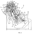
- FIG. 2 is a side elevational view, partly in vertical cross section, of the engine (a cross-sectional view taken along line 2 - 2 of FIG. 3).
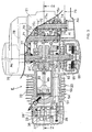
- FIG. 3 is a cross-sectional view taken along line 3 - 3 of FIG. 2.
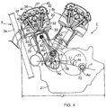
- FIG. 4 is a side elevational view, partly in vertical cross section, of an engine according to a second embodiment of the present invention.
- front refers to directions with respect to a motorcycle M to which the present invention is applied.
- a motorcycle M has a vehicle frame F including a head pipe 1, a main tube 2 welded to an upper portion of the head pipe 1 and extending rearwardly and downwardly at a low gradient, and a down tube 3 welded to a lower portion of the head pipe 1.
- the down tube 3 includes a downward portion 3a extending downwardly from the head pipe 1, and a horizontal portion 3b bent rearwardly from the lower end of the downward portion 3a.
- a central tube 4 extending downwardly from an intermediate portion of the main tube 2 is connected to the rear end of the horizontal portion 3b.
- a stay 5 is connected between the main tube 2 and the down tube 3 in the vicinity of the head pipe 1.
- An engine E supported by the down tube 3 and the stay 5 is disposed in a space which is surrounded by the main tube 2, the down tube 3, the stay 5, and the central tube 4.
- a front fork 7 on which a front wheel 6f is rotatably supported is steerably pivotally supported on the head pipe 1.
- a rear fork 8 on which a rear wheel 6r is supported is pivotally supported on the rear end of the down tube 3 through a pivot shaft 9.
- a rear cushion 10 is connected between the rear fork 8 and the main tube 2.
- a fuel tank 11 and a saddle 12 are disposed on the main tube 2.
- the engine E has an engine body 20 including a crankcase 21, a cylinder block 22 coupled to an upper portion of the front end of the crankcase 21 and projecting upwardly and forwardly therefrom, and a cylinder head 23 joined to the upper end of the cylinder block 22.
- a crankshaft 28 housed in the crankcase 21 is supported on the left and right side walls of the crankcase 21 by bearings 27, 27'.
- a piston 29 slidingly movable in a single cylinder bore 22a in the cylinder block 22 is connected to the crankshaft 28 by a connecting rod 30.
- the cylinder head 23 has a combustion chamber 31 faced by the top surface of the piston 29, an intake port 32 communicating with the combustion chamber 31 and opening at a rear surface of the cylinder head 23, and an exhaust port 33 communicating with the combustion chamber 31 and opening at a front surface of the cylinder head 23.
- An intake valve 34 and an exhaust valve 35 for opening and closing the intake port 32 and the exhaust port 33, respectively, are mounted in the cylinder head 23.
- the intake valve 34 and the exhaust valve 35 are operated by a valve operating mechanism 36 which is disposed in a valve operating chamber 37 in the cylinder head 23.
- the valve operating mechanism 36 includes a camshaft 38 rotatably supported on the cylinder head 23 by a pair of left and right bearings 39, 39' parallel to the crankshaft 28 in a position intermediate between the intake and exhaust valves 34, 35, an intake rocker arm 40 pivotally supported on the cylinder head 23 and operatively interconnecting the camshaft 38 and the intake valve 34, an exhaust rocker arm 41 pivotally supported on the cylinder head 23 and operatively interconnecting the camshaft 38 and the exhaust valve 35, and valve springs 42, 43 for normally biasing the intake and exhaust valves 34, 35, respectively, in a valve closing direction.
- the camshaft 38 is operatively coupled to the crankshaft 28 by a timing transmission device 51.
- the timing transmission device 51 includes a drive sprocket 52 fixed to the crankshaft 28 disposed outwardly of and adjacent to the left bearing 27 which supports the crankshaft 28, a driven sprocket 53 fixed to an end of the camshaft 38, and an endless timing chain 54 trained around the sprockets 52, 53.
- the timing transmission device 51 is capable of transmitting rotation of the crankshaft 28 to the camshaft 38 at a speed reduction ratio of 1/2.
- the timing chain 54 is disposed in a timing chain passage 55 that is defined in a side wall of the cylinder block 22.
- a carburetor 13 (see FIG. 1) connected to the intake port 32 is connected to the rear surface of the cylinder head 23.
- An exhaust pipe 14 (see also FIG. 1) connected to the exhaust port 33 is connected to the front surface of the cylinder head 23, and a muffler 15 is connected to the rear end of the exhaust pipe 14.
- the cylinder block 22 is disposed such that the cylinder bore 22a has its axis Ab is offset forwardly a distance e with respect to an axis Ac of the crankshaft 28. With the front end of the cylinder head 23 being positioned as closely to the downward portion 3a of the down tube 3 as possible in the same manner as the conventional engine, the axis Ab of the cylinder block 22 rises from the horizontal plane through a relatively sharp angle ⁇ . Preferably, the cylinder block 22 is arranged to extend parallel to the downward portion 3a of the down tube 3.
- a breather chamber 57 is defined in a portion of the crankcase 21 close to the rear surface of the cylinder block 22.
- the breather chamber 57 has an inlet 57a communicating with the interior of the crankcase 21 and an outlet 57b communicating with an intake system including the carburetor 13 through a breather pipe 59.
- the interior of the breather chamber 57 is constructed as a labyrinth between the inlet 57a and the outlet 57b for separating a lubricating oil from a blow-by gas produced in the crankcase 21 while the blow-by gas is passing through the breather chamber 57.
- a generator 60 has a rotor 61 keyed to one end of the crankshaft 28.
- the rotor 61 is connected to a starter gear 62 which is rotatably supported on the crankshaft 28 by a one-way clutch 63.
- the one-way clutch 63 transmits rotational forces from the starter gear 62 to the rotor 61 in one direction only.
- the starter gear 62 is rotated through a speed reduction gear train by a starter motor 65 which is mounted on a front portion of the crankcase 21 below the cylinder block 22.
- the crankcase 21 accommodates a transmission 70 having an input shaft 71 and an output shaft 72 which extend parallel to the crankshaft 28.
- the input and output shafts 71, 72 are supported on the opposite side walls of the crankcase 21 by respective pairs of bearings 73, 73' and 74, 74'.
- Transmission gear trains 75 1 through 75 n is interposed between the input and output shafts 71, 72.
- Power generated by the crankshaft 28 is transmitted through a centrifugal clutch 76, a primary speed reduction gear train 77, and a transmission clutch 78 to the input shaft 71, and then transmitted from the input shaft 71 through a selected transmission gear train to the output shaft 72, from which the power is transmitted through a chain transmitting device 79 (see FIG. 1) disposed outside of the crankcase 21 to the rear wheel 6r, thus rotating the rear wheel 6r.
- the input shaft 71 is disposed such that its axis Ai is offset upwardly a distance s with respect to a plane P which includes the axes Ac, Ao of the crankshaft 28 and the output shaft 72 at a position intermediate between the crankshaft 28 and the output shaft 72.
- FIG. 2 shows the outline of a conventional engine E' as indicated by the chain lines.
- a comparison between the outlines of the engine E according to the present invention and the conventional engine E' shows that with the front end of the cylinder head 23 being positioned as closely to the downward portion 3a of the down tube 3 as possible, the cylinder block 22 is arranged such that the angle ⁇ through which the axis Ab of the cylinder block 22 rises from the horizontal plane is greater than the conventional angle ⁇ ' and the axis Ab of the cylinder block 22 passes forwardly of the axis Ac of the crankshaft 28. Therefore, a free upper area of the crankcase 21 which is not obstructed by the cylinder block 22 is widened without changing the position of the front end of the engine E.
- the upward offset s of the input shaft 71 with respect to the horizontal plane P can be sufficiently made greater than the conventional offset s' without being obstructed by the cylinder block 22, thus effectively making the interaxial distance L 1 between the crankshaft 28 and the output shaft 72 much smaller than the conventional interaxial distance L 1 '.
- the size of the crankcase 21 in the longitudinal direction of the motorcycle is made compact, thus greatly reducing the overall length L 2 of the engine E in the longitudinal direction of the motorcycle so as to be smaller than the conventional overall length L 2 ' for thereby effectively making the engine E compact.
- the cylinder block 22 is parallel to the downward portion 3a of the down tube 3 of the vehicle frame F, the dead space between the downward portion 3a and the cylinder head 23 is minimized for thereby reducing the wheelbase of the motorcycle M.
- the breather chamber 57 is defined in the portion of the crankcase 21 close to the rear surface of the cylinder block 22, the dead space between the cylinder block 22 and the input shaft 71 in the crankcase 21 is effectively utilized to form the breather chamber 57, further making the engine E compact.
- FIG. 4 A second embodiment of the present invention as shown in FIG. 4 will be described below.
- the present invention is applied to a V-shaped engine E having a front bank Bf and a rear bank Br.
- the front bank Bf corresponds to the cylinder block 22 and the cylinder head 23 according to the first embodiment.
- the rear bank Br is arranged such that the axis Ab of the cylinder block 22 thereof is offset forwardly a distance e with respect to the axis Ac of the crankshaft 28 in order to avoid interference with the transmission 70.
- the forward offset of the cylinder block axis Ab from the crankshaft axis Ac of the front bank Bf and the forward offset of the cylinder block axis Ab from the crankshaft axis Ac of the rear bank Br are set to equal distances e. However, these offsets may be set to different distances.
- the present invention is not limited to the above embodiments, but may be modified in design without departing from the scope thereof. It is an object in an engine for motorcycles to sufficiently increase an upward offset of a transmission input shaft without being obstructed by a cylinder block, thus shortening the overall length of the engine in the longitudinal direction of the motorcycle.
- the cylinder block 22 is disposed to have its axis Ab passing forwardly of the axis Ac of the crankshaft 28. It is thus possible to sufficiently increase an upward offset of the transmission input shaft without being obstructed by the cylinder block.
Landscapes
- Engineering & Computer Science (AREA)
- Chemical & Material Sciences (AREA)
- Combustion & Propulsion (AREA)
- Mechanical Engineering (AREA)
- General Engineering & Computer Science (AREA)
- Cylinder Crankcases Of Internal Combustion Engines (AREA)
- Automatic Cycles, And Cycles In General (AREA)
Abstract
Description
- The present invention relates to an engine for a motorcycle, and more particularly to an engine for a motorcycle having a crankcase, a cylinder block extending upwardly and forwardly of a motor vehicle from an upper portion of the front end of the crankcase, and a cylinder head joined to the upper end of the cylinder block, the crankcase housing and supporting a crankshaft, a transmission input shaft, and a transmission output shaft which are arranged to have their axes oriented transversely of the motor vehicle. The transmission input shaft is offset upwardly with respect to a plane which includes the axes of the crankshaft and the transmission output shaft.
- Conventional engines for motorcycles generally have a cylinder block arranged to have its axis extending across the axis of the crankshaft (see, for example, Japanese Patent Laid-open No. Hei 11-29085).
- In such engines for motorcycles, offsetting a transmission input shaft upwardly with respect to a plane which includes the axes of a crankshaft and a transmission output shaft is effective to reduce the interaxial distance between the crankshaft and the transmission output shaft thereby to shorten the overall length of the engine in the longitudinal direction of the motorcycle for making the engine compact. However, the conventional engines fail to provide a sufficient upward offset of the transmission input shaft because of the cylinder block which is positioned in the way. One solution would be to reduce the angle through which the cylinder block rises from the horizontal plane in order to provide a sufficient upward offset of the transmission input shaft. However, since the front end of the cylinder head would be shifted forwardly, there would be an increase in the overall length of the engine in the longitudinal direction of the motorcycle, canceling out the reduction in the overall length of the engine in the longitudinal direction of the motorcycle, which is provided by the increased upward offset of the transmission input shaft.
- The present invention has been made in view of the above drawbacks. It is an object of the present invention to provide an engine for motorcycles which has a transmission input shaft of which the upward offset is sufficiently increased without being obstructed by the cylinder block to effectively reduce the overall length of the engine in the longitudinal direction of the motorcycle.
- To achieve the above object, there is provided in accordance with a first feature of the present invention an engine for a motorcycle having a crankcase, a cylinder block extending upwardly and forwardly of a motor vehicle from an upper portion of the front end of the crankcase, and a cylinder head joined to the upper end of the cylinder block, the crankcase housing and supporting a crankshaft, a transmission input shaft, and a transmission output shaft which are arranged to have their axes oriented transversely of the motor vehicle, the transmission input shaft being offset upwardly with respect to a plane which includes the axes of the crankshaft and the transmission output shaft, characterized in that the cylinder block is disposed to have its axis passing forwardly of the axis of the crankshaft.
- According to the above first feature, with the cylinder block being disposed to have its axis passing forwardly of the axis of the crankshaft, if the angle through which the axis of the cylinder block rises from the horizontal plane is increased, then a free upper area of the crankcase which is not obstructed by the cylinder block is widened without changing the position of the front end of the engine. Therefore, the upward offset of the input shaft with respect to the horizontal plane can be sufficiently increased without being obstructed by the cylinder block, thus effectively shortening the interaxial distance between the crankshaft and the output shaft. As a result, the size of the crankcase in the longitudinal direction of the motorcycle is made compact, thus reducing the overall length of the engine in the longitudinal direction of the motorcycle for thereby effectively making the engine compact.
- The offset of the axis of the cylinder block with respect to the axis of the crankshaft causes a reduction in the angle of inclination of the connecting rod under a maximum pressure in the expansion stroke of the engine. As a result, a side thrust which the piston receives from the inner surface of the cylinder bore is reduced, reducing the frictional resistance to the sliding motion of the piston, which contributes to lower fuel consumption.
- According to a second feature of the present invention, in addition to the first feature, the cylinder block is disposed substantially parallel to a downward portion of a down tube of a vehicle frame.
- According to the second feature, the dead space between the down tube and the cylinder head is minimized to reduce the wheelbase of the motorcycle.
- According to a third feature of the present invention, in addition to the first and second features, a breather chamber communicating with the interior of the crankcase is mounted on a portion of the crankcase near a rear surface of the cylinder block.
- According to the third feature, the dead space present between the cylinder block and the input shaft in the crankcase is effectively utilized to form the breather chamber, further making the engine compact.
- Embodiments of the present invention will be described below with reference to the accompanying drawings.
- FIG. 1 is a side elevational view of a motorcycle which incorporates an engine according to a first embodiment of the present invention.
- FIG. 2 is a side elevational view, partly in vertical cross section, of the engine (a cross-sectional view taken along line 2 - 2 of FIG. 3).
- FIG. 3 is a cross-sectional view taken along line 3 - 3 of FIG. 2.
- FIG. 4 is a side elevational view, partly in vertical cross section, of an engine according to a second embodiment of the present invention.
- The terms "front", "rear", "longitudinal", "left", "right", and "transverse" used in the description refer to directions with respect to a motorcycle M to which the present invention is applied.
- A first embodiment of the present invention as shown in FIGS. 1 and 2 will first be described below. In FIG. 1, a motorcycle M has a vehicle frame F including a head pipe 1, a
main tube 2 welded to an upper portion of the head pipe 1 and extending rearwardly and downwardly at a low gradient, and adown tube 3 welded to a lower portion of the head pipe 1. Thedown tube 3 includes adownward portion 3a extending downwardly from the head pipe 1, and ahorizontal portion 3b bent rearwardly from the lower end of thedownward portion 3a. A central tube 4 extending downwardly from an intermediate portion of themain tube 2 is connected to the rear end of thehorizontal portion 3b. A stay 5 is connected between themain tube 2 and thedown tube 3 in the vicinity of the head pipe 1. An engine E supported by thedown tube 3 and the stay 5 is disposed in a space which is surrounded by themain tube 2, thedown tube 3, the stay 5, and the central tube 4. - A
front fork 7 on which afront wheel 6f is rotatably supported is steerably pivotally supported on the head pipe 1. Arear fork 8 on which arear wheel 6r is supported is pivotally supported on the rear end of thedown tube 3 through a pivot shaft 9. Arear cushion 10 is connected between therear fork 8 and themain tube 2. - A
fuel tank 11 and asaddle 12 are disposed on themain tube 2. - As shown in FIGS. 2 and 3, the engine E has an
engine body 20 including acrankcase 21, acylinder block 22 coupled to an upper portion of the front end of thecrankcase 21 and projecting upwardly and forwardly therefrom, and acylinder head 23 joined to the upper end of thecylinder block 22. - A
crankshaft 28 housed in thecrankcase 21 is supported on the left and right side walls of thecrankcase 21 bybearings 27, 27'. Apiston 29 slidingly movable in a single cylinder bore 22a in thecylinder block 22 is connected to thecrankshaft 28 by a connectingrod 30. - The
cylinder head 23 has a combustion chamber 31 faced by the top surface of thepiston 29, anintake port 32 communicating with the combustion chamber 31 and opening at a rear surface of thecylinder head 23, and anexhaust port 33 communicating with the combustion chamber 31 and opening at a front surface of thecylinder head 23. Anintake valve 34 and anexhaust valve 35 for opening and closing theintake port 32 and theexhaust port 33, respectively, are mounted in thecylinder head 23. Theintake valve 34 and theexhaust valve 35 are operated by avalve operating mechanism 36 which is disposed in avalve operating chamber 37 in thecylinder head 23. - The
valve operating mechanism 36 includes acamshaft 38 rotatably supported on thecylinder head 23 by a pair of left andright bearings 39, 39' parallel to thecrankshaft 28 in a position intermediate between the intake andexhaust valves intake rocker arm 40 pivotally supported on thecylinder head 23 and operatively interconnecting thecamshaft 38 and theintake valve 34, anexhaust rocker arm 41 pivotally supported on thecylinder head 23 and operatively interconnecting thecamshaft 38 and theexhaust valve 35, andvalve springs exhaust valves - The
camshaft 38 is operatively coupled to thecrankshaft 28 by atiming transmission device 51. Thetiming transmission device 51 includes a drive sprocket 52 fixed to thecrankshaft 28 disposed outwardly of and adjacent to theleft bearing 27 which supports thecrankshaft 28, a drivensprocket 53 fixed to an end of thecamshaft 38, and anendless timing chain 54 trained around thesprockets 52, 53. Thetiming transmission device 51 is capable of transmitting rotation of thecrankshaft 28 to thecamshaft 38 at a speed reduction ratio of 1/2. Thetiming chain 54 is disposed in atiming chain passage 55 that is defined in a side wall of thecylinder block 22. - A carburetor 13 (see FIG. 1) connected to the
intake port 32 is connected to the rear surface of thecylinder head 23. An exhaust pipe 14 (see also FIG. 1) connected to theexhaust port 33 is connected to the front surface of thecylinder head 23, and amuffler 15 is connected to the rear end of theexhaust pipe 14. - The
cylinder block 22 is disposed such that thecylinder bore 22a has its axis Ab is offset forwardly a distance e with respect to an axis Ac of thecrankshaft 28. With the front end of thecylinder head 23 being positioned as closely to thedownward portion 3a of thedown tube 3 as possible in the same manner as the conventional engine, the axis Ab of thecylinder block 22 rises from the horizontal plane through a relatively sharp angle . Preferably, thecylinder block 22 is arranged to extend parallel to thedownward portion 3a of thedown tube 3. - A
breather chamber 57 is defined in a portion of thecrankcase 21 close to the rear surface of thecylinder block 22. Thebreather chamber 57 has aninlet 57a communicating with the interior of thecrankcase 21 and anoutlet 57b communicating with an intake system including thecarburetor 13 through abreather pipe 59. The interior of thebreather chamber 57 is constructed as a labyrinth between theinlet 57a and theoutlet 57b for separating a lubricating oil from a blow-by gas produced in thecrankcase 21 while the blow-by gas is passing through thebreather chamber 57. - A
generator 60 has arotor 61 keyed to one end of thecrankshaft 28. Therotor 61 is connected to a starter gear 62 which is rotatably supported on thecrankshaft 28 by a one-way clutch 63. The one-way clutch 63 transmits rotational forces from the starter gear 62 to therotor 61 in one direction only. The starter gear 62 is rotated through a speed reduction gear train by astarter motor 65 which is mounted on a front portion of thecrankcase 21 below thecylinder block 22. - The
crankcase 21 accommodates atransmission 70 having aninput shaft 71 and anoutput shaft 72 which extend parallel to thecrankshaft 28. The input andoutput shafts crankcase 21 by respective pairs ofbearings output shafts crankshaft 28 is transmitted through acentrifugal clutch 76, a primary speedreduction gear train 77, and atransmission clutch 78 to theinput shaft 71, and then transmitted from theinput shaft 71 through a selected transmission gear train to theoutput shaft 72, from which the power is transmitted through a chain transmitting device 79 (see FIG. 1) disposed outside of thecrankcase 21 to therear wheel 6r, thus rotating therear wheel 6r. - In the
transmission 70, theinput shaft 71 is disposed such that its axis Ai is offset upwardly a distance s with respect to a plane P which includes the axes Ac, Ao of thecrankshaft 28 and theoutput shaft 72 at a position intermediate between thecrankshaft 28 and theoutput shaft 72. - Operation of the above embodiment will be described below.
- FIG. 2 shows the outline of a conventional engine E' as indicated by the chain lines. A comparison between the outlines of the engine E according to the present invention and the conventional engine E' shows that with the front end of the
cylinder head 23 being positioned as closely to thedownward portion 3a of thedown tube 3 as possible, thecylinder block 22 is arranged such that the angle through which the axis Ab of thecylinder block 22 rises from the horizontal plane is greater than the conventional angle ' and the axis Ab of thecylinder block 22 passes forwardly of the axis Ac of thecrankshaft 28. Therefore, a free upper area of thecrankcase 21 which is not obstructed by thecylinder block 22 is widened without changing the position of the front end of the engine E. Therefore, the upward offset s of theinput shaft 71 with respect to the horizontal plane P can be sufficiently made greater than the conventional offset s' without being obstructed by thecylinder block 22, thus effectively making the interaxial distance L1 between thecrankshaft 28 and theoutput shaft 72 much smaller than the conventional interaxial distance L1'. As a result, the size of thecrankcase 21 in the longitudinal direction of the motorcycle is made compact, thus greatly reducing the overall length L2 of the engine E in the longitudinal direction of the motorcycle so as to be smaller than the conventional overall length L2' for thereby effectively making the engine E compact. Particularly, if thecylinder block 22 is parallel to thedownward portion 3a of thedown tube 3 of the vehicle frame F, the dead space between thedownward portion 3a and thecylinder head 23 is minimized for thereby reducing the wheelbase of the motorcycle M. - The offset of the axis Ab of the
cylinder bore 22a with respect to the axis Ac of thecrankshaft 28 causes a reduction in the angle of inclination of the connectingrod 30 under a maximum pressure in the expansion stroke of the engine E. As a result, a side thrust which thepiston 29 receives from the inner surface of thecylinder bore 22a is reduced, reducing the frictional resistance to the sliding motion of thepiston 29, which contributes to lower fuel consumption. - Since the
breather chamber 57 is defined in the portion of thecrankcase 21 close to the rear surface of thecylinder block 22, the dead space between thecylinder block 22 and theinput shaft 71 in thecrankcase 21 is effectively utilized to form thebreather chamber 57, further making the engine E compact. - A second embodiment of the present invention as shown in FIG. 4 will be described below.
- According to the present invention, the present invention is applied to a V-shaped engine E having a front bank Bf and a rear bank Br. The front bank Bf corresponds to the
cylinder block 22 and thecylinder head 23 according to the first embodiment. The rear bank Br is arranged such that the axis Ab of thecylinder block 22 thereof is offset forwardly a distance e with respect to the axis Ac of thecrankshaft 28 in order to avoid interference with thetransmission 70. In the illustrated embodiment, the forward offset of the cylinder block axis Ab from the crankshaft axis Ac of the front bank Bf and the forward offset of the cylinder block axis Ab from the crankshaft axis Ac of the rear bank Br are set to equal distances e. However, these offsets may be set to different distances. - Other structural details of the second embodiment are identical to those of the first embodiment. Therefore, those parts of the second embodiment which correspond to those of the first embodiment are denoted by identical reference characters, and will not be described in detail below.
- The present invention is not limited to the above embodiments, but may be modified in design without departing from the scope thereof.
It is an object in an engine for motorcycles to sufficiently increase an upward offset of a transmission input shaft without being obstructed by a cylinder block, thus shortening the overall length of the engine in the longitudinal direction of the motorcycle.
To achieve this, in an engine for a motorcycle having acylinder block 22 extending upwardly and forwardly of a motor vehicle M from an upper portion of the front end of acrankcase 21, and atransmission input shaft 71 offset upwardly with respect to a plane P which includes the axes Ac, Ao of acrankshaft 28 and atransmission output shaft 72, thecylinder block 22 is disposed to have its axis Ab passing forwardly of the axis Ac of thecrankshaft 28. It is thus possible to sufficiently increase an upward offset of the transmission input shaft without being obstructed by the cylinder block.
Claims (3)
- An engine for a motorcycle having a crankcase (21), a cylinder block (22) extending upwardly and forwardly of a motor vehicle (M) from an upper portion of the front end of the crankcase (21), and a cylinder head (23) joined to the upper end of the cylinder block (22), the crankcase (21) housing and supporting a crankshaft (28), a transmission input shaft (71), and a transmission output shaft (72) which are arranged to have their axes (Ac, Ai, Ao) oriented transversely of the motor vehicle, said transmission input shaft (71) being offset upwardly with respect to a plane (P) which includes the axes (Ac, Ao) of the crankshaft (28) and the transmission output shaft (72), characterized in that the cylinder block (22) is disposed to have its axis (Ab) passing forwardly of the axis (Ac) of the crankshaft (28).
- An engine for a motorcycle according to claim 1, characterized in that the cylinder block (22) is disposed substantially parallel to a downward portion (3a) of a down tube (3) of a vehicle frame (F).
- An engine for a motorcycle according to claim 1 or 2, characterized in that a breather chamber (57) communicating with the interior of the crankcase (21) is mounted on a portion of the crankcase (21) near a rear surface of the cylinder block (22).
Applications Claiming Priority (2)
| Application Number | Priority Date | Filing Date | Title |
|---|---|---|---|
| JP2001026372 | 2001-02-02 | ||
| JP2001026372A JP3986760B2 (en) | 2001-02-02 | 2001-02-02 | Motorcycle engine |
Publications (3)
| Publication Number | Publication Date |
|---|---|
| EP1228956A2 true EP1228956A2 (en) | 2002-08-07 |
| EP1228956A3 EP1228956A3 (en) | 2003-05-07 |
| EP1228956B1 EP1228956B1 (en) | 2007-11-07 |
Family
ID=18891200
Family Applications (1)
| Application Number | Title | Priority Date | Filing Date |
|---|---|---|---|
| EP02000883A Expired - Lifetime EP1228956B1 (en) | 2001-02-02 | 2002-01-15 | Engine for motorcycles |
Country Status (9)
| Country | Link |
|---|---|
| US (1) | US6637398B2 (en) |
| EP (1) | EP1228956B1 (en) |
| JP (1) | JP3986760B2 (en) |
| KR (1) | KR100504625B1 (en) |
| CN (1) | CN1183317C (en) |
| BR (1) | BR0200296B1 (en) |
| DE (1) | DE60223304T2 (en) |
| ES (1) | ES2295245T3 (en) |
| TW (1) | TWI222944B (en) |
Cited By (6)
| Publication number | Priority date | Publication date | Assignee | Title |
|---|---|---|---|---|
| KR100504625B1 (en) * | 2001-02-02 | 2005-08-01 | 혼다 기켄 고교 가부시키가이샤 | Engine for motor cycle |
| ES2264598A1 (en) * | 2003-03-19 | 2007-01-01 | Honda Motor Co., Ltd. | Forced-air-cooled engine |
| DE102004042765B4 (en) * | 2004-09-05 | 2007-07-19 | Clemens Neese | Motorcycle with a space and weight-saving engine arrangement |
| CN100378305C (en) * | 2003-10-15 | 2008-04-02 | 雅马哈发动机株式会社 | Two-wheeled motor vehicles and engines for two-wheeled motor vehicles |
| EP3663547A4 (en) * | 2017-08-03 | 2020-08-12 | Yamaha Hatsudoki Kabushiki Kaisha | ENGINE AND VEHICLE |
| EP3663559A4 (en) * | 2017-08-03 | 2020-08-26 | Yamaha Hatsudoki Kabushiki Kaisha | ENGINE AND VEHICLE |
Families Citing this family (22)
| Publication number | Priority date | Publication date | Assignee | Title |
|---|---|---|---|---|
| JP3618094B2 (en) * | 2002-04-24 | 2005-02-09 | 川崎重工業株式会社 | V-type engine for vehicles |
| CN100412332C (en) * | 2003-07-10 | 2008-08-20 | 雅马哈发动机株式会社 | Engines for Riding Vehicles |
| JP4096863B2 (en) * | 2003-11-07 | 2008-06-04 | トヨタ自動車株式会社 | Engine starting device and engine starting method |
| US7168405B2 (en) * | 2004-01-30 | 2007-01-30 | Hartley Jr John J | Camshaft drive mechanism |
| ES2283163B1 (en) * | 2004-03-22 | 2008-08-01 | Emiliano Lopez Cano Toribio | APPLICATION OF DIESEL ENGINES TO MOTORCYCLES. |
| US6941920B1 (en) * | 2004-04-02 | 2005-09-13 | Kenneth R. Thurm | Motorcycle engine and transmission interbracing member |
| US20060037811A1 (en) * | 2004-08-20 | 2006-02-23 | S & S Cycle, Inc. | Muffler assembly |
| JP4563824B2 (en) * | 2005-01-18 | 2010-10-13 | 本田技研工業株式会社 | Motorcycle engine |
| JP2008143511A (en) | 2006-11-15 | 2008-06-26 | Yamaha Motor Co Ltd | Body frame and vehicle |
| US7966986B2 (en) * | 2007-04-13 | 2011-06-28 | Hyspan Precision Products, Inc. | Cylinder head |
| JP4680971B2 (en) * | 2007-09-28 | 2011-05-11 | 本田技研工業株式会社 | Exhaust control device for vehicle engine |
| CN101482069B (en) * | 2008-01-10 | 2012-07-04 | 光阳工业股份有限公司 | Cylinder structure of vehicle engine |
| US8403100B2 (en) * | 2008-08-08 | 2013-03-26 | Yamaha Motor Co., Ltd. | Vehicle and vehicle exhaust pipe |
| CN101746474A (en) * | 2008-12-17 | 2010-06-23 | 光阳工业股份有限公司 | motorcycle engine structure |
| JP5219883B2 (en) * | 2009-02-24 | 2013-06-26 | 本田技研工業株式会社 | Starter motor arrangement structure of internal combustion engine |
| US8857417B2 (en) * | 2009-12-30 | 2014-10-14 | Kawasaki Jukogyo Kabushiki Kaisha | Engine for vehicle |
| JP5323883B2 (en) * | 2011-04-14 | 2013-10-23 | 本田技研工業株式会社 | Motorcycle internal combustion engine |
| JP5750430B2 (en) * | 2012-12-26 | 2015-07-22 | 本田技研工業株式会社 | Casing structure of in-vehicle internal combustion engine |
| JP6333787B2 (en) * | 2015-09-25 | 2018-05-30 | 本田技研工業株式会社 | Breather chamber structure of internal combustion engine |
| DE102016117251B4 (en) | 2016-09-14 | 2019-08-22 | Iav Gmbh Ingenieurgesellschaft Auto Und Verkehr | Motorcycle with compact reciprocating internal combustion engine |
| JP7122227B2 (en) * | 2018-11-02 | 2022-08-19 | カワサキモータース株式会社 | straddle-type vehicle |
| JP2020148132A (en) * | 2019-03-13 | 2020-09-17 | ヤマハ発動機株式会社 | Saddle-type vehicle |
Family Cites Families (11)
| Publication number | Priority date | Publication date | Assignee | Title |
|---|---|---|---|---|
| JPS58113646A (en) * | 1981-12-26 | 1983-07-06 | Honda Motor Co Ltd | motorcycle |
| JPS5969514A (en) * | 1982-10-09 | 1984-04-19 | Honda Motor Co Ltd | Crankshaft for internal-combustion engine |
| JP2647823B2 (en) * | 1984-07-31 | 1997-08-27 | ヤマハ発動機株式会社 | Motorcycle |
| US4945866A (en) * | 1987-03-26 | 1990-08-07 | Chabot Jr Bertin R | Altered piston timing engine |
| JP2726459B2 (en) * | 1988-12-01 | 1998-03-11 | ヤマハ発動機株式会社 | Piston / crank mechanism |
| JPH0524452A (en) * | 1991-03-28 | 1993-02-02 | Mazda Motor Corp | Vehicle powertrain structure |
| US5857538A (en) * | 1996-01-31 | 1999-01-12 | Chambers; Herbert M. | Motorcycle |
| JP4042872B2 (en) | 1997-07-09 | 2008-02-06 | ヤマハ発動機株式会社 | Driving device for motorcycle |
| US6058901A (en) * | 1998-11-03 | 2000-05-09 | Ford Global Technologies, Inc. | Offset crankshaft engine |
| JP4318782B2 (en) * | 1999-03-31 | 2009-08-26 | 本田技研工業株式会社 | 4-cycle engine lubrication structure |
| JP3986760B2 (en) * | 2001-02-02 | 2007-10-03 | 本田技研工業株式会社 | Motorcycle engine |
-
2001
- 2001-02-02 JP JP2001026372A patent/JP3986760B2/en not_active Expired - Fee Related
-
2002
- 2002-01-15 DE DE60223304T patent/DE60223304T2/en not_active Expired - Lifetime
- 2002-01-15 EP EP02000883A patent/EP1228956B1/en not_active Expired - Lifetime
- 2002-01-15 ES ES02000883T patent/ES2295245T3/en not_active Expired - Lifetime
- 2002-01-29 TW TW091101460A patent/TWI222944B/en not_active IP Right Cessation
- 2002-01-30 CN CNB021032408A patent/CN1183317C/en not_active Ceased
- 2002-02-01 BR BRPI0200296-5A patent/BR0200296B1/en not_active IP Right Cessation
- 2002-02-01 US US10/060,250 patent/US6637398B2/en not_active Expired - Fee Related
- 2002-02-01 KR KR10-2002-0005844A patent/KR100504625B1/en not_active Expired - Fee Related
Non-Patent Citations (1)
| Title |
|---|
| None |
Cited By (9)
| Publication number | Priority date | Publication date | Assignee | Title |
|---|---|---|---|---|
| KR100504625B1 (en) * | 2001-02-02 | 2005-08-01 | 혼다 기켄 고교 가부시키가이샤 | Engine for motor cycle |
| ES2264598A1 (en) * | 2003-03-19 | 2007-01-01 | Honda Motor Co., Ltd. | Forced-air-cooled engine |
| ES2264598B1 (en) * | 2003-03-19 | 2007-12-01 | Honda Motor Co., Ltd. | FORCED AIR COOLED ENGINE. |
| CN100378305C (en) * | 2003-10-15 | 2008-04-02 | 雅马哈发动机株式会社 | Two-wheeled motor vehicles and engines for two-wheeled motor vehicles |
| CN100378304C (en) * | 2003-10-15 | 2008-04-02 | 雅马哈发动机株式会社 | Two-wheeled motor vehicles and engines for two-wheeled motor vehicles |
| DE102004042765B4 (en) * | 2004-09-05 | 2007-07-19 | Clemens Neese | Motorcycle with a space and weight-saving engine arrangement |
| US7753012B2 (en) | 2004-09-05 | 2010-07-13 | Clemens Neese | Motorcycle comprising a compact internal combustion engine |
| EP3663547A4 (en) * | 2017-08-03 | 2020-08-12 | Yamaha Hatsudoki Kabushiki Kaisha | ENGINE AND VEHICLE |
| EP3663559A4 (en) * | 2017-08-03 | 2020-08-26 | Yamaha Hatsudoki Kabushiki Kaisha | ENGINE AND VEHICLE |
Also Published As
| Publication number | Publication date |
|---|---|
| US20020104504A1 (en) | 2002-08-08 |
| EP1228956B1 (en) | 2007-11-07 |
| TWI222944B (en) | 2004-11-01 |
| KR20020064673A (en) | 2002-08-09 |
| EP1228956A3 (en) | 2003-05-07 |
| CN1183317C (en) | 2005-01-05 |
| US6637398B2 (en) | 2003-10-28 |
| JP3986760B2 (en) | 2007-10-03 |
| DE60223304T2 (en) | 2008-02-21 |
| BR0200296A (en) | 2002-10-29 |
| JP2002227601A (en) | 2002-08-14 |
| ES2295245T3 (en) | 2008-04-16 |
| DE60223304D1 (en) | 2007-12-20 |
| BR0200296B1 (en) | 2010-07-13 |
| KR100504625B1 (en) | 2005-08-01 |
| CN1369628A (en) | 2002-09-18 |
Similar Documents
| Publication | Publication Date | Title |
|---|---|---|
| EP1228956B1 (en) | Engine for motorcycles | |
| US6725958B2 (en) | Snowmobile | |
| JP4384457B2 (en) | engine | |
| US7216615B2 (en) | Engine device for motorcycles | |
| US6651635B2 (en) | Breather apparatus for four-cycle engine | |
| KR100472316B1 (en) | Engine for Backbone-type Motorcycle | |
| US7438031B2 (en) | Layout structure of hydraulic control valve for valve train in internal combustion engine | |
| JPH09257029A (en) | V-type engine crankshaft bearing device | |
| JP3470355B2 (en) | Dry sump engine oil passage | |
| JP3336270B2 (en) | Parallel 4-cylinder engine | |
| JP2002235548A (en) | Parallel 4-cylinder engine | |
| TWI235192B (en) | Oil return construction of 4-cycle engine | |
| JP7022219B2 (en) | Internal combustion engine | |
| JPH09287470A (en) | Vehicles with supercharged engine | |
| JPH09287465A (en) | Vehicles with supercharged engine | |
| JP4105057B2 (en) | Internal combustion engine with starter motor | |
| JP2002213216A (en) | Parallel 4-cylinder engine | |
| JPH01211623A (en) | V-engine | |
| JPH108981A (en) | Motorcycle engine | |
| JP2002206428A (en) | Water-cooled parallel 4-cylinder engine | |
| JP2005042558A (en) | Engine unit for saddle-ride type vehicles | |
| JP2000130144A (en) | Breather device for vertical engine | |
| JP2002201925A (en) | Engine | |
| JP2001073795A (en) | Mounting structure of supercharger for unit swing type internal combustion engine | |
| JPH08232673A (en) | Engine generator layout structure |
Legal Events
| Date | Code | Title | Description |
|---|---|---|---|
| PUAI | Public reference made under article 153(3) epc to a published international application that has entered the european phase |
Free format text: ORIGINAL CODE: 0009012 |
|
| AK | Designated contracting states |
Kind code of ref document: A2 Designated state(s): AT BE CH CY DE DK ES FI FR GB GR IE IT LI LU MC NL PT SE TR |
|
| AX | Request for extension of the european patent |
Free format text: AL;LT;LV;MK;RO;SI |
|
| PUAL | Search report despatched |
Free format text: ORIGINAL CODE: 0009013 |
|
| AK | Designated contracting states |
Designated state(s): AT BE CH CY DE DK ES FI FR GB GR IE IT LI LU MC NL PT SE TR |
|
| AX | Request for extension of the european patent |
Extension state: AL LT LV MK RO SI |
|
| 17P | Request for examination filed |
Effective date: 20030618 |
|
| AKX | Designation fees paid |
Designated state(s): DE ES IT |
|
| 17Q | First examination report despatched |
Effective date: 20061109 |
|
| GRAP | Despatch of communication of intention to grant a patent |
Free format text: ORIGINAL CODE: EPIDOSNIGR1 |
|
| GRAS | Grant fee paid |
Free format text: ORIGINAL CODE: EPIDOSNIGR3 |
|
| GRAA | (expected) grant |
Free format text: ORIGINAL CODE: 0009210 |
|
| AK | Designated contracting states |
Kind code of ref document: B1 Designated state(s): DE ES IT |
|
| REF | Corresponds to: |
Ref document number: 60223304 Country of ref document: DE Date of ref document: 20071220 Kind code of ref document: P |
|
| REG | Reference to a national code |
Ref country code: ES Ref legal event code: FG2A Ref document number: 2295245 Country of ref document: ES Kind code of ref document: T3 |
|
| PLBE | No opposition filed within time limit |
Free format text: ORIGINAL CODE: 0009261 |
|
| STAA | Information on the status of an ep patent application or granted ep patent |
Free format text: STATUS: NO OPPOSITION FILED WITHIN TIME LIMIT |
|
| 26N | No opposition filed |
Effective date: 20080808 |
|
| REG | Reference to a national code |
Ref country code: DE Ref legal event code: R084 Ref document number: 60223304 Country of ref document: DE Effective date: 20111128 |
|
| PGFP | Annual fee paid to national office [announced via postgrant information from national office to epo] |
Ref country code: DE Payment date: 20120111 Year of fee payment: 11 |
|
| PGFP | Annual fee paid to national office [announced via postgrant information from national office to epo] |
Ref country code: IT Payment date: 20120118 Year of fee payment: 11 |
|
| PGFP | Annual fee paid to national office [announced via postgrant information from national office to epo] |
Ref country code: ES Payment date: 20120213 Year of fee payment: 11 |
|
| PG25 | Lapsed in a contracting state [announced via postgrant information from national office to epo] |
Ref country code: DE Free format text: LAPSE BECAUSE OF NON-PAYMENT OF DUE FEES Effective date: 20130801 |
|
| REG | Reference to a national code |
Ref country code: DE Ref legal event code: R119 Ref document number: 60223304 Country of ref document: DE Effective date: 20130801 |
|
| PG25 | Lapsed in a contracting state [announced via postgrant information from national office to epo] |
Ref country code: IT Free format text: LAPSE BECAUSE OF NON-PAYMENT OF DUE FEES Effective date: 20130115 |
|
| REG | Reference to a national code |
Ref country code: ES Ref legal event code: FD2A Effective date: 20140509 |
|
| PG25 | Lapsed in a contracting state [announced via postgrant information from national office to epo] |
Ref country code: ES Free format text: LAPSE BECAUSE OF NON-PAYMENT OF DUE FEES Effective date: 20130116 |