EP1228732B1 - Household vacuum cleaner with a wide suction head - Google Patents
Household vacuum cleaner with a wide suction head Download PDFInfo
- Publication number
- EP1228732B1 EP1228732B1 EP02002335A EP02002335A EP1228732B1 EP 1228732 B1 EP1228732 B1 EP 1228732B1 EP 02002335 A EP02002335 A EP 02002335A EP 02002335 A EP02002335 A EP 02002335A EP 1228732 B1 EP1228732 B1 EP 1228732B1
- Authority
- EP
- European Patent Office
- Prior art keywords
- suction
- vacuum cleaner
- suction head
- channel
- base plate
- Prior art date
- Legal status (The legal status is an assumption and is not a legal conclusion. Google has not performed a legal analysis and makes no representation as to the accuracy of the status listed.)
- Expired - Lifetime
Links
- 239000004753 textile Substances 0.000 claims abstract description 4
- 239000002184 metal Substances 0.000 claims description 3
- 239000000428 dust Substances 0.000 description 3
- 239000000047 product Substances 0.000 description 2
- 238000010276 construction Methods 0.000 description 1
- 238000004519 manufacturing process Methods 0.000 description 1
- 239000000463 material Substances 0.000 description 1
- 239000006228 supernatant Substances 0.000 description 1
Images

Classifications
-
- A—HUMAN NECESSITIES
- A47—FURNITURE; DOMESTIC ARTICLES OR APPLIANCES; COFFEE MILLS; SPICE MILLS; SUCTION CLEANERS IN GENERAL
- A47L—DOMESTIC WASHING OR CLEANING; SUCTION CLEANERS IN GENERAL
- A47L9/00—Details or accessories of suction cleaners, e.g. mechanical means for controlling the suction or for effecting pulsating action; Storing devices specially adapted to suction cleaners or parts thereof; Carrying-vehicles specially adapted for suction cleaners
- A47L9/02—Nozzles
- A47L9/06—Nozzles with fixed, e.g. adjustably fixed brushes or the like
- A47L9/0606—Nozzles with fixed, e.g. adjustably fixed brushes or the like rigidly anchored brushes, combs, lips or pads
- A47L9/0626—Rigidly anchored lips, e.g. nozzles adapted for picking up liquids
-
- A—HUMAN NECESSITIES
- A47—FURNITURE; DOMESTIC ARTICLES OR APPLIANCES; COFFEE MILLS; SPICE MILLS; SUCTION CLEANERS IN GENERAL
- A47L—DOMESTIC WASHING OR CLEANING; SUCTION CLEANERS IN GENERAL
- A47L9/00—Details or accessories of suction cleaners, e.g. mechanical means for controlling the suction or for effecting pulsating action; Storing devices specially adapted to suction cleaners or parts thereof; Carrying-vehicles specially adapted for suction cleaners
- A47L9/02—Nozzles
- A47L9/06—Nozzles with fixed, e.g. adjustably fixed brushes or the like
- A47L9/0606—Nozzles with fixed, e.g. adjustably fixed brushes or the like rigidly anchored brushes, combs, lips or pads
- A47L9/0613—Nozzles with fixed, e.g. adjustably fixed brushes or the like rigidly anchored brushes, combs, lips or pads with means specially adapted for picking up threads, hair or the like, e.g. brushes, combs, lint pickers or bristles pads
-
- A—HUMAN NECESSITIES
- A47—FURNITURE; DOMESTIC ARTICLES OR APPLIANCES; COFFEE MILLS; SPICE MILLS; SUCTION CLEANERS IN GENERAL
- A47L—DOMESTIC WASHING OR CLEANING; SUCTION CLEANERS IN GENERAL
- A47L9/00—Details or accessories of suction cleaners, e.g. mechanical means for controlling the suction or for effecting pulsating action; Storing devices specially adapted to suction cleaners or parts thereof; Carrying-vehicles specially adapted for suction cleaners
- A47L9/02—Nozzles
- A47L9/06—Nozzles with fixed, e.g. adjustably fixed brushes or the like
- A47L9/0633—Nozzles with fixed, e.g. adjustably fixed brushes or the like with retractable brushes, combs, lips or pads
- A47L9/064—Nozzles with fixed, e.g. adjustably fixed brushes or the like with retractable brushes, combs, lips or pads actuating means therefor
- A47L9/0653—Nozzles with fixed, e.g. adjustably fixed brushes or the like with retractable brushes, combs, lips or pads actuating means therefor with mechanical actuation, e.g. using a lever
Definitions
- the invention relates to a household vacuum cleaner with a usable both smooth floors and textile floor coverings suction head, which is rigidly or tiltably mounted on a housing upper sliding sole with a transversely extending to the working direction suction mouth, a mouth opening into the suction port and a vertical in the upper housing part comprising adjustable arranged and operable by a switch carrier having at least one lower-side bristle strip and / or at least one lower-side flexible lip.
- the sliding sole has underside projecting, the suction mouth limiting Saugmundkanten and is equipped with at least one thread lifter strip.
- the suction channel has a connection end for a rotary / tilting joint, which consists of a pivotally inserted into the suction port and a rotatably connected to the nozzle angle tube.
- the intended for household use vacuum cleaner also has in a conventional manner a suction device with a suction fan and a dust collector.
- the speed of the suction fan is generally stepless or adjustable in stages.
- the dust collecting device may consist of a collecting container designed as a separator, a filter bag or a filter bag designed as a disposable article.
- the suction device further comprises a housing which is pulled on rollers or runners on the bottom surface to be cleaned and is connected via a suction hose and a suction tube connected to the suction tube to the suction head.
- a household vacuum cleaner based on the invention achieves a maximum air flow of between 25 and 50 l / sec measured in accordance with DIN EN 60 312.
- suction head for household vacuum cleaner which is also referred to as a vacuum cleaner nozzle
- a vacuum cleaner nozzle DE-A 196 28 070 known and widely used in practice.
- the suction heads have a width up to about 300 millimeters.
- Wider suction nozzles are only used for industrial vacuum cleaners.
- the designed for the industrial suction nozzles have a different structure compared to floor nozzles for household vacuum cleaners. They have a narrow in the suction direction of the upper housing part, in which a suction mouth forming insert is fitted.
- the suction head has neither a wide sliding sole nor a vertically adjustable in the upper housing part carrier with associated switch.
- the insert which forms the suction mouth is exchangeable and is adapted with regard to the specific design for the purpose for which the suction nozzle is primarily intended.
- WO 96/37 142 is known a floor nozzle whose width is twice as large as the width of a floor nozzle for household vacuum cleaner. It has a suction mouth, the is divided in the middle by a bridge. In each section of the suction mouth opens a suction channel.
- the floor nozzle has no vertically adjustable support and is not switchable for alternating operation on smooth floors and textile floor coverings. As an advantage it is stated that the wide suction nozzle results in a more stable ground contact. A contribution to energy-efficient suction does not make the document.
- the invention has for its object to allow a household vacuum cleaner as energy efficient as possible suction.
- the object is achieved in that the sliding sole of the suction head has a measured at the ends of the suction mouth working width of 350 to 500 millimeters.
- the suction head according to the invention has a particularly large working width for household vacuum cleaner.
- the embodiment of the invention is based on the consideration that the nozzle width is proportional to a performance index, which refers to the power consumption of the vacuum cleaner on the suctioned surface.
- the suction head can be designed so that the calculated as a product of air flow and negative pressure suction with increasing working width not or only slightly changes.
- an energy-efficient suction is possible with a vacuum cleaner nozzle, which according to the invention may have a working width of 350 to 500 millimeters.
- the bottom-side pressure force is greater in the design of the suction head, which is the teaching of the invention is based.
- the increase in the pressure force and the resulting sliding force to move the suction head over the bottom surface can be counteracted by choice of material of the sliding sole and / or by a front support on rollers.
- the sliding sole made of plastic.
- a metal soleplate is preferred.
- long thread lifter strips are used. They may according to a preferred embodiment of the invention have a length which is 0.3 to 0.5 times the working width of the sliding sole.
- the canister vacuum cleaner may comprise a housing with a suction fan and a dust collecting device, which is drawn in a slide shape on rollers or runners on the bottom surface to be cleaned and connected via a suction hose and a suction tube connected to the suction tube to the suction head.
- a suction-side nozzle which is coupled directly without the interposition of a suction hose to the suction head.
- the handsets At the rear end, the handsets have a handle with a handle.
- an upper housing part 1 a rigidly or tiltably attached to the upper housing part 1 sole 2 with a transversely to the working direction extending suction mouth 3, a suction channel 4, which opens into the suction port 3 and a connecting end for a Turning / tilting joint 5, as well as an operable by a switch 8 carrier 9, which is vertically adjustable in the upper housing part 1 and equipped for sucking smooth floors on the underside with at least one bristle strip 10 and / or at least one flexible lip.
- the rotary / tilting joint 5 consists of a pivotally inserted into the suction port 4 and 6 a rotatably connected to the nozzle 6 angle tube 7, to which a connected via a suction hose to the vacuum cleaner suction pipe or the suction-side nozzle of the vacuum cleaner can be connected.
- the sliding sole 2 has underside projecting, the suction mouth 3 delimiting Saugmundkanten 11 and is equipped with at least one thread lifter strip 12.
- the suction mouth 3 consists of a single channel, which has an approximately constant channel width in its length.
- the sliding sole 2 may consist of plastic or metal and has in the working direction behind the suction mouth to a width which is a multiple of the channel width.
- working width B of the sliding sole 2 is greater than 350 millimeters. It can be up to 500 millimeters.
- the thread lifter strip 12 has a length which should be 0.3 to 0.5 times the working width B of the sliding sole 2.
- the household vacuum cleaner on which the invention is based generates a maximum air flow of between 25 and 50 l / sec determined in accordance with DIN EN 60 312.
- the suction power determined according to this DIN which is calculated as the product of air flow and negative pressure, is preferably in the range from 150 watts to 400 watts.
Abstract
Description
Die Erfindung betrifft einen Haushalts-Bodenstaubsauger mit einem sowohl auf Glattböden als auch auf textilen Bodenbelägen einsetzbaren Saugkopf, der eine an einem Gehäuseoberteil starr oder kippbeweglich befestigte Gleitsohle mit einem quer zur Arbeitsrichtung sich erstreckenden Saugmund, einen in den Saugmund einmündenden Saugkanal und einen im Gehäuseoberteil vertikal verstellbar angeordneten und von einem Umschalter betätigbaren Träger mit mindestens einem unterseitigen Borstenstreifen und/oder mindestens einer unterseitigen flexiblen Lippe aufweist. Die Gleitsohle weist unterseitig vorspringende, den Saugmund begrenzende Saugmundkanten auf und ist mit mindestens einem Fadenheberstreifen ausgerüstet ist. Der Saugkanal hat ein Anschlussende für ein Dreh-/Kippgelenk, das aus einem schwenkbeweglich in den Saugkanal eingesetzten Stutzen und einem drehbeweglich an den Stutzen angeschlossenen Winkelrohr besteht. Der für den Hausgebrauch bestimmte Bodenstaubsauger weist ferner in an sich bekannter Weise eine Saugeinrichtung mit einem Sauggebläse und einer Staubsammeleinrichtung auf. Die Drehzahl des Sauggebläses ist im allgemeinen stufenlos oder in Stufen regelbar. Die Staubsammeleinrichtung kann aus einem als Abscheider ausgebildeten Auffangbehälter, einem Filtersack oder einer als Wegwerfartikel ausgebildeten Filtertüte bestehen. Die Saugeinrichtung weist ferner ein Gehäuse auf, das auf Rollen oder Kufen über die zu reinigende Bodenfläche gezogen wird und über einen Saugschlauch und einen mit dem Saugschlauch verbundenes Saugrohr an den Saugkopf angeschlossen ist. Unter den Begriff Bodenstaubsauger sollen aber auch Handgeräte fallen, die auf das Anschlussende des Saugkopfes aufgesteckt werden und an ihrem rückwärtigen Ende zur Handhabung eine Stange mit einem Handgriff aufweisen. Ein der Erfindung zugrundeliegender Haushalts-Bodenstaubsauger erreicht einen nach DIN EN 60 312 gemessenen maximalen Luftstrom zwischen 25 und 50 l/sec.The invention relates to a household vacuum cleaner with a usable both smooth floors and textile floor coverings suction head, which is rigidly or tiltably mounted on a housing upper sliding sole with a transversely extending to the working direction suction mouth, a mouth opening into the suction port and a vertical in the upper housing part comprising adjustable arranged and operable by a switch carrier having at least one lower-side bristle strip and / or at least one lower-side flexible lip. The sliding sole has underside projecting, the suction mouth limiting Saugmundkanten and is equipped with at least one thread lifter strip. The suction channel has a connection end for a rotary / tilting joint, which consists of a pivotally inserted into the suction port and a rotatably connected to the nozzle angle tube. The intended for household use vacuum cleaner also has in a conventional manner a suction device with a suction fan and a dust collector. The speed of the suction fan is generally stepless or adjustable in stages. The dust collecting device may consist of a collecting container designed as a separator, a filter bag or a filter bag designed as a disposable article. The suction device further comprises a housing which is pulled on rollers or runners on the bottom surface to be cleaned and is connected via a suction hose and a suction tube connected to the suction tube to the suction head. Under the term vacuum cleaner but also hand tools fall, which are plugged onto the connecting end of the suction head and at its rear end for handling a rod with a handle. A household vacuum cleaner based on the invention achieves a maximum air flow of between 25 and 50 l / sec measured in accordance with DIN EN 60 312.
Der eingangs beschriebene Aufbau eines Saugkopfes für Haushalts-Bodenstaubsauger, der auch als Staubsaugerdüse bezeichnet wird, ist beispielsweise aus
Breitere Saugdüsen werden lediglich für Industrieschmutzsauger eingesetzt. Die für den Industriebereich ausgelegten Saugdüsen weisen im Vergleich zu Bodendüsen für Haushalts-Staubsauger einen anderen Aufbau auf. Sie weisen einen in Saugrichtung schmales Gehäuseoberteil auf, in das ein den Saugmund formender Einsatz eingepasst ist. Der Saugkopf weist weder eine breite Gleitsohle noch einen im Gehäuseoberteil vertikal verstellbaren Träger mit zugeordnetem Umschalter auf. Der den Saugmund formende Einsatz ist austauschbar und wird bezüglich der konkreten Gestaltung für den Einsatzzweck, für den die Saugdüse vornehmlich bestimmt ist, angepasst.Wider suction nozzles are only used for industrial vacuum cleaners. The designed for the industrial suction nozzles have a different structure compared to floor nozzles for household vacuum cleaners. They have a narrow in the suction direction of the upper housing part, in which a suction mouth forming insert is fitted. The suction head has neither a wide sliding sole nor a vertically adjustable in the upper housing part carrier with associated switch. The insert which forms the suction mouth is exchangeable and is adapted with regard to the specific design for the purpose for which the suction nozzle is primarily intended.
Aus
Der Erfindung liegt die Aufgabe zugrunde, bei einem Haushalts-Bodenstaubsauger ein möglichst energieeffizientes Saugen zu ermöglichen.The invention has for its object to allow a household vacuum cleaner as energy efficient as possible suction.
Ausgehend von einem Haushalts-Bodenstaubsauger, dessen Saugkopf die eingangs beschriebenen Merkmale aufweist, wird die Aufgabe erfindungsgemäß dadurch gelöst, dass die Gleitsohle des Saugkopfes eine an den Enden des Saugmundes gemessene Arbeitsbreite von 350 bis 500 Millimetern aufweist. Im Vergleich zu den bekannten Ausführungen weist der erfindungsgemäße Saugkopf eine für Haushalts-Bodenstaubsauger besonders große Arbeitsbreite auf. Die erfindungsgemäße Ausbildung beruht auf der Überlegung, dass die Düsenbreite proportional in eine Leistungskennziffer eingeht, welche die Leistungsaufnahme des Bodenstaubsaugers auf die abgesaugte Fläche bezieht. Durch die unterseitige Gestaltung der Gleitsohle, insbesondere durch die Bemessung des Saugmundes, des Überstandes und der Breite der Saugmundkanten sowie des rückwärtig an den Saugmund anschließenden Abschnittes der Gleitsohle kann der Saugkopf so ausgelegt werden, dass die als Produkt aus Luftstrom und Unterdruck berechnete Saugleistung sich mit zunehmender Arbeitsbreite nicht oder nur wenig ändert. Insofern ist mit einer Staubsaugerdüse, die erfindungsgemäß eine Arbeitsbreite von 350 bis 500 Millimetern besitzen kann, ein energieeffizientes Saugen möglich. Mit zunehmender Arbeitsbreite wird bei der Bauform des Saugkopfes, die der erfindungsgemäßen Lehre zugrunde liegt, die bodenseitige Andruckkraft größer. Der Vergrößerung der Andruckkraft und der daraus resultierenden Schiebekraft zur Bewegung des Saugkopfes über die Bodenfläche kann durch Materialwahl der Gleitsohle und/oder durch eine frontseitige Abstützung an Gleitrollen entgegengewirkt werden.Starting from a household vacuum cleaner whose suction head has the features described above, the object is achieved in that the sliding sole of the suction head has a measured at the ends of the suction mouth working width of 350 to 500 millimeters. In comparison to the known embodiments, the suction head according to the invention has a particularly large working width for household vacuum cleaner. The embodiment of the invention is based on the consideration that the nozzle width is proportional to a performance index, which refers to the power consumption of the vacuum cleaner on the suctioned surface. Due to the underside design of the soleplate, in particular by the design of the suction mouth, the supernatant and the width of the Saugmundkanten and the rear of the suction mouth adjacent portion of the sole plate, the suction head can be designed so that the calculated as a product of air flow and negative pressure suction with increasing working width not or only slightly changes. In this respect, an energy-efficient suction is possible with a vacuum cleaner nozzle, which according to the invention may have a working width of 350 to 500 millimeters. With increasing working width, the bottom-side pressure force is greater in the design of the suction head, which is the teaching of the invention is based. The increase in the pressure force and the resulting sliding force to move the suction head over the bottom surface can be counteracted by choice of material of the sliding sole and / or by a front support on rollers.
Im Rahmen der Erfindung liegt es, die Gleitsohle aus Kunststoff zu fertigen. Bevorzugt ist jedoch eine Gleitsohle aus Metall. Zweckmäßig werden lange Fadenheberstreifen eingesetzt. Sie können gemäß einer bevorzugten Ausführung der Erfindung eine Länge aufweisen, die das 0,3- bis 0,5-fache der Arbeitsbreite der Gleitsohle beträgt.In the context of the invention is to manufacture the sliding sole made of plastic. However, a metal soleplate is preferred. Appropriately, long thread lifter strips are used. They may according to a preferred embodiment of the invention have a length which is 0.3 to 0.5 times the working width of the sliding sole.
Im Folgenden wird die Erfindung anhand einer lediglich ein Ausführungsbeispiel darstellenden Zeichnung näher erläutert. Es zeigen schematisch
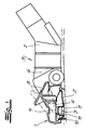
- Fig. 1
- einen Längsschnitt durch einen Saugkopf für einen Haushalts-Bodenstaubsauger,
- Fig. 2
- eine Unteransicht des in
Fig. 1 dargestellten Saugkopfes.
- Fig. 1
- a longitudinal section through a suction head for a household vacuum cleaner,
- Fig. 2
- a bottom view of the in
Fig. 1 illustrated suction head.
In den Figuren ist ein in der Praxis als Staubsaugerdüse bezeichneter Saugkopf für einen Haushalts-Bodenstaubsauger dargestellt. Der Bodenstaubsauger kann ein Gehäuse mit einem Sauggebläse und einer Staubsammeleinrichtung aufweisen, der schlittenförmig auf Rollen oder Kufen über die zu reinigende Bodenfläche gezogen wird und über einen Saugschlauch sowie ein mit dem Saugschlauch verbundenes Saugrohr an den Saugkopf angeschlossen ist. Von dem Begriff Bodenstaubsauger sollen aber auch Handgeräte erfasst sein, die einen saugseitigen Stutzen aufweisen, der unmittelbar ohne Zwischenschaltung eines Saugschlauches an den Saugkopf angekuppelt wird. An ihrem rückwärtigen Ende weisen die Handgeräte einen Stiel mit einem Handgriff auf.In the figures, a designated in practice as a vacuum cleaner suction head for a household vacuum cleaner is shown. The canister vacuum cleaner may comprise a housing with a suction fan and a dust collecting device, which is drawn in a slide shape on rollers or runners on the bottom surface to be cleaned and connected via a suction hose and a suction tube connected to the suction tube to the suction head. From the term vacuum cleaner but also hand tools should be detected, which have a suction-side nozzle, which is coupled directly without the interposition of a suction hose to the suction head. At the rear end, the handsets have a handle with a handle.
Zu dem grundsätzlichen Aufbau des in den Figuren dargestellten Saugkopfes gehören ein Gehäuseoberteil 1, eine am Gehäuseoberteil 1 starr oder kippbeweglich befestigte Gleitsohle 2 mit einem quer zur Arbeitsrichtung sich erstreckenden Saugmund 3, ein Saugkanal 4, der in den Saugmund 3 einmündet und ein Anschlussende für ein Dreh-/Kippgelenk 5 aufweist, sowie ein von einem Umschalter 8 betätigbarer Träger 9, der vertikal verstellbar im Gehäuseoberteil 1 angeordnet und zum Saugen von Glattböden unterseitig mit mindestens einem Borstenstreifen 10 und/oder mindestens einer flexiblen Lippe bestückt ist. Das Dreh-/Kippgelenk 5 besteht aus einem schwenkbeweglich in den Saugkanal 4 eingesetzten Stutzen 6 und einem drehbeweglich an den Stutzen 6 angeschlossenen Winkelrohr 7, an das ein über einen Saugschlauch mit dem Bodenstaubsauger verbundenes Saugrohr oder der saugseitige Stutzen des Staubsaugers anschließbar ist. Die Gleitsohle 2 weist unterseitig vorspringende, den Saugmund 3 begrenzende Saugmundkanten 11 auf und ist mit mindestens einem Fadenheberstreifen 12 ausgerüstet. Der Saugmund 3 besteht aus einem einzigen Kanal, der in seiner Länge eine annähernd konstante Kanalbreite aufweist. Die Gleitsohle 2 kann aus Kunststoff oder Metall bestehen und weist in Arbeitsrichtung hinter dem Saugmund eine Breite auf, die ein Mehrfaches der Kanalbreite beträgt.To the basic structure of the suction head shown in the figures include an upper housing part 1, a rigidly or tiltably attached to the upper housing part 1 sole 2 with a transversely to the working direction extending
Erfindungsgemäß ist die an den Enden des Saugmundes 3 gemessene Arbeitsbreite B der Gleitsohle 2 größer als 350 Millimeter. Sie kann bis zu 500 Millimeter betragen. Der Fadenheberstreifen 12 hat eine Länge, die das 0,3- bis 0,5-fache der Arbeitsbreite B der Gleitsohle 2 betragen sollte.According to the measured at the ends of the
Der der Erfindung zugrundeliegende Haushalts-Bodenstaubsauger erzeugt einen nach DIN EN 60 312 bestimmten maximalen Luftstrom zwischen 25 und 50 l/sec. Die nach dieser DIN bestimmte Saugleistung, die als Produkt aus Luftstrom und Unterdruck berechnet wird, liegt vorzugsweise im Bereich vom 150 Watt bis 400 Watt.The household vacuum cleaner on which the invention is based generates a maximum air flow of between 25 and 50 l / sec determined in accordance with DIN EN 60 312. The suction power determined according to this DIN, which is calculated as the product of air flow and negative pressure, is preferably in the range from 150 watts to 400 watts.
Claims (3)
- Domestic vacuum cleaner comprising a suction head which can be used both on smooth floors and on textile floor coverings, which suction head has a sliding base plate (2) which is attached in a rigid or tiltable manner to a housing upper part (1) and comprises a suction mouth (3) which extends transversely to the working direction and consists of a single channel, a suction channel (4) which opens into the suction mouth (3), and a carrier (9) which is arranged in a vertically displaceable manner in the housing upper part (1) and can be actuated by a switch (8), said carrier comprising at least one strip of bristles (10) on the underside and/or at least one flexible lip on the underside, wherein the sliding base plate (2) has suction mouth edges (11) which delimit the suction mouth (3) and protrude from the underside, and is equipped with at least one pile-lifting strip (12), wherein the suction channel (4) has a connection end for a rotary/tilting articulation (5) which consists of a pivotable connection piece (6) inserted in the suction channel (4) and an angled tube (7) which is connected in a rotatable manner to the connection piece (6), and wherein the suction mouth (3) has over its length an approximately constant channel width, characterised in that the sliding base plate (2) has a working width (B) of 350 to 500 mm measured to the ends of the suction mouth (3).
- Domestic vacuum cleaner according to claim 1, characterised in that the sliding base plate (2) of the suction head is made from metal.
- Domestic vacuum cleaner according to claim 1 or 2, characterised in that the pile-lifting strip (12) of the suction head has a length which is 0.3 to 0.5 times the working width (B) of the sliding base plate (2).
Applications Claiming Priority (2)
| Application Number | Priority Date | Filing Date | Title |
|---|---|---|---|
| DE10105371 | 2001-02-06 | ||
| DE10105371A DE10105371A1 (en) | 2001-02-06 | 2001-02-06 | Suction head for household canister vacuum cleaners |
Publications (3)
| Publication Number | Publication Date |
|---|---|
| EP1228732A2 EP1228732A2 (en) | 2002-08-07 |
| EP1228732A3 EP1228732A3 (en) | 2004-12-08 |
| EP1228732B1 true EP1228732B1 (en) | 2008-09-17 |
Family
ID=7673053
Family Applications (1)
| Application Number | Title | Priority Date | Filing Date |
|---|---|---|---|
| EP02002335A Expired - Lifetime EP1228732B1 (en) | 2001-02-06 | 2002-01-31 | Household vacuum cleaner with a wide suction head |
Country Status (5)
| Country | Link |
|---|---|
| EP (1) | EP1228732B1 (en) |
| CN (1) | CN1242719C (en) |
| AT (1) | ATE408361T1 (en) |
| DE (2) | DE10105371A1 (en) |
| HK (1) | HK1045930B (en) |
Families Citing this family (14)
| Publication number | Priority date | Publication date | Assignee | Title |
|---|---|---|---|---|
| ITMI20041075A1 (en) * | 2004-05-28 | 2004-08-28 | New Ermes Europe Spa | IMPROVED MECHANISM FOR HANDLING A RUBBING-LIFTING INSERTS IN A VACUUM HEAD FOR VACUUM CLEANERS |
| KR100582519B1 (en) * | 2004-07-09 | 2006-05-23 | 삼성광주전자 주식회사 | A suction brush assembly of a vacuum cleaner |
| DE202005020507U1 (en) * | 2005-12-20 | 2006-04-13 | Alfred Kärcher Gmbh & Co. Kg | Floor nozzle for vacuum cleaner |
| US8671513B2 (en) | 2006-10-11 | 2014-03-18 | Samsung Electronics Co., Ltd. | Nozzle assembly having subsidiary brush unit |
| EP1913856B1 (en) * | 2006-10-20 | 2011-07-27 | Wessel-Werk GmbH | Compact suction cleaning device for autonomous cleaning of floor coverings |
| DE102007009958B4 (en) * | 2007-03-01 | 2013-08-01 | Wessel-Werk Gmbh | Sheet-metal sole and method for its design |
| AU2011253852B2 (en) * | 2010-12-15 | 2014-06-05 | Bissell Inc. | Suction nozzle with shuttling plate and converging debris paths |
| DE102012106570B4 (en) * | 2012-07-19 | 2014-08-28 | Wessel-Werk Gmbh | Vacuum cleaner nozzle, in particular for household vacuum cleaners |
| DE102013108893B4 (en) * | 2013-08-16 | 2019-03-14 | Wessel-Werk Gmbh | vacuum cleaner nozzle |
| DE102015101019A1 (en) * | 2015-01-23 | 2016-07-28 | Wessel-Werk Gmbh | Plastic sliding sole for a vacuum cleaner nozzle |
| DE102015105061B4 (en) | 2015-04-01 | 2022-03-24 | Vorwerk & Co. Interholding Gmbh | cleaning device |
| DE102015108052B4 (en) * | 2015-05-21 | 2020-02-13 | Vorwerk & Co. Interholding Gmbh | Suction nozzle for the collection of coarse and fine dust |
| FR3078878B1 (en) * | 2018-03-14 | 2022-08-19 | Seb Sa | VACUUM NOZZLE WITH A SLIDING SURFACE WITH A ROUNDED BACK EDGE |
| EP3659483B1 (en) * | 2018-11-30 | 2023-06-14 | Aktiebolaget Electrolux | Nozzle for a vacuum cleaner and vacuum cleaner comprising a nozzle |
Family Cites Families (8)
| Publication number | Priority date | Publication date | Assignee | Title |
|---|---|---|---|---|
| DE3009648C2 (en) * | 1980-03-13 | 1983-03-17 | Hans 5226 Reichshof Wessel | Vacuum cleaner nozzle with a connection element and a sliding sole |
| DE4201596C2 (en) * | 1992-01-22 | 2001-07-05 | Gerhard Kurz | Floor nozzle for vacuum cleaners |
| DE4243244C2 (en) * | 1992-12-19 | 1999-11-04 | Miele & Cie | Wheeled floor nozzle for vacuum cleaners |
| DE19546756C2 (en) * | 1995-04-07 | 1997-12-18 | Guenther Heidt | High pressure cleaning device |
| SE9501912D0 (en) * | 1995-05-21 | 1995-05-21 | Goeran Edlund | Device for connection to vacuum conducting line |
| DE19541739A1 (en) * | 1995-11-09 | 1997-05-15 | Vorwerk Co Interholding | Wetting and vacuum floor cleaning machine |
| DE19628070C2 (en) * | 1996-07-12 | 1999-05-20 | Wessel Werk Gmbh | Three-purpose vacuum cleaner |
| DE20020253U1 (en) * | 2000-11-22 | 2001-04-26 | Wessel Werk Gmbh | Vacuum cleaner nozzle |
-
2001
- 2001-02-06 DE DE10105371A patent/DE10105371A1/en not_active Withdrawn
-
2002
- 2002-01-31 AT AT02002335T patent/ATE408361T1/en not_active IP Right Cessation
- 2002-01-31 DE DE50212775T patent/DE50212775D1/en not_active Expired - Lifetime
- 2002-01-31 EP EP02002335A patent/EP1228732B1/en not_active Expired - Lifetime
- 2002-02-06 CN CNB021004935A patent/CN1242719C/en not_active Expired - Fee Related
- 2002-10-22 HK HK02107640.7A patent/HK1045930B/en not_active IP Right Cessation
Also Published As
| Publication number | Publication date |
|---|---|
| HK1045930A1 (en) | 2002-12-20 |
| DE50212775D1 (en) | 2008-10-30 |
| EP1228732A2 (en) | 2002-08-07 |
| EP1228732A3 (en) | 2004-12-08 |
| CN1242719C (en) | 2006-02-22 |
| CN1370499A (en) | 2002-09-25 |
| DE10105371A1 (en) | 2002-08-14 |
| ATE408361T1 (en) | 2008-10-15 |
| HK1045930B (en) | 2006-07-14 |
Similar Documents
| Publication | Publication Date | Title |
|---|---|---|
| EP1228732B1 (en) | Household vacuum cleaner with a wide suction head | |
| DE69918564T2 (en) | CONSTRUCTION OF A VACUUM CLEANER | |
| EP2989953B1 (en) | Use of a suction nozzle which can be connected to a vacuum cleaner for suction of a textile floor surface, a tiled hard floor surface and a smooth unjoined hard floor surface | |
| DE4411526A1 (en) | Suction cleaning device | |
| EP3047775B1 (en) | Sliding sole made from plastic for a vacuum cleaner nozzle | |
| DE202004002284U1 (en) | Self-propelled vacuum cleaner | |
| DE2556335A1 (en) | VACUUM MOUTH PIECE | |
| EP3025626A1 (en) | Floor nozzle for floor treating machine and method for producing a floor nozzle for floor treating machine | |
| EP2116165B1 (en) | Suction nozzle for a vacuum cleaner | |
| EP0898923B1 (en) | Suction nozzle for vacuum cleaner | |
| EP1595485B1 (en) | Nozzle for vaccum cleaner | |
| DE102015108052B4 (en) | Suction nozzle for the collection of coarse and fine dust | |
| EP2937029B1 (en) | Suction nozzle for suction of smooth surfaces, in particular of tiled ground surfaces | |
| EP1935307B1 (en) | Floor nozzle for a vacuum cleaner | |
| WO2012000937A1 (en) | Vacuum cleaner nozzle | |
| EP0818173B1 (en) | Triple function nozzle for vacuum cleaner | |
| DE2846468A1 (en) | HOUSING FOR THE KNOCKING DEVICE OF A VACUUM CLEANER | |
| DE3143355A1 (en) | Suction nozzle for taking up liquids | |
| DE102018207844B3 (en) | Floor cleaning element and associated vacuum cleaner | |
| DE4112394A1 (en) | Plug-in vacuum cleaner head - uses inclined bristles with hooked ends and possible adjustment of angle of bristle incline | |
| WO2007025906A1 (en) | Floor nozzle for a vacuum cleaner, comprising an adjustable strip of bristles | |
| DE2153453C3 (en) | Vacuum cleaner nozzle with retractable brush | |
| EP0917437B1 (en) | Floor-cleaning device for wet- and vacuum cleaning | |
| WO1997026819A2 (en) | Method of and device for operating a vacuum cleaner | |
| DE102005041805A1 (en) | Staubsaugerbodendüse |
Legal Events
| Date | Code | Title | Description |
|---|---|---|---|
| PUAI | Public reference made under article 153(3) epc to a published international application that has entered the european phase |
Free format text: ORIGINAL CODE: 0009012 |
|
| AK | Designated contracting states |
Kind code of ref document: A2 Designated state(s): AT BE CH CY DE DK ES FI FR GB GR IE IT LI LU MC NL PT SE TR |
|
| AX | Request for extension of the european patent |
Free format text: AL;LT;LV;MK;RO;SI |
|
| PUAL | Search report despatched |
Free format text: ORIGINAL CODE: 0009013 |
|
| AK | Designated contracting states |
Kind code of ref document: A3 Designated state(s): AT BE CH CY DE DK ES FI FR GB GR IE IT LI LU MC NL PT SE TR |
|
| AX | Request for extension of the european patent |
Extension state: AL LT LV MK RO SI |
|
| 17P | Request for examination filed |
Effective date: 20041207 |
|
| AKX | Designation fees paid |
Designated state(s): AT BE CH CY DE DK ES FI FR GB GR IE IT LI LU MC NL PT SE TR |
|
| 17Q | First examination report despatched |
Effective date: 20060222 |
|
| RAP3 | Party data changed (applicant data changed or rights of an application transferred) |
Owner name: WESSEL-WERK GMBH |
|
| GRAP | Despatch of communication of intention to grant a patent |
Free format text: ORIGINAL CODE: EPIDOSNIGR1 |
|
| RTI1 | Title (correction) |
Free format text: HOUSEHOLD VACUUM CLEANER WITH A WIDE SUCTION HEAD |
|
| GRAS | Grant fee paid |
Free format text: ORIGINAL CODE: EPIDOSNIGR3 |
|
| GRAA | (expected) grant |
Free format text: ORIGINAL CODE: 0009210 |
|
| AK | Designated contracting states |
Kind code of ref document: B1 Designated state(s): AT BE CH CY DE DK ES FI FR GB GR IE IT LI LU MC NL PT SE TR |
|
| REG | Reference to a national code |
Ref country code: GB Ref legal event code: FG4D Free format text: NOT ENGLISH |
|
| REG | Reference to a national code |
Ref country code: CH Ref legal event code: EP |
|
| REG | Reference to a national code |
Ref country code: IE Ref legal event code: FG4D Free format text: LANGUAGE OF EP DOCUMENT: GERMAN |
|
| REF | Corresponds to: |
Ref document number: 50212775 Country of ref document: DE Date of ref document: 20081030 Kind code of ref document: P |
|
| REG | Reference to a national code |
Ref country code: SE Ref legal event code: TRGR |
|
| PG25 | Lapsed in a contracting state [announced via postgrant information from national office to epo] |
Ref country code: FI Free format text: LAPSE BECAUSE OF FAILURE TO SUBMIT A TRANSLATION OF THE DESCRIPTION OR TO PAY THE FEE WITHIN THE PRESCRIBED TIME-LIMIT Effective date: 20080917 |
|
| REG | Reference to a national code |
Ref country code: IE Ref legal event code: FD4D |
|
| PG25 | Lapsed in a contracting state [announced via postgrant information from national office to epo] |
Ref country code: ES Free format text: LAPSE BECAUSE OF FAILURE TO SUBMIT A TRANSLATION OF THE DESCRIPTION OR TO PAY THE FEE WITHIN THE PRESCRIBED TIME-LIMIT Effective date: 20081228 |
|
| PG25 | Lapsed in a contracting state [announced via postgrant information from national office to epo] |
Ref country code: PT Free format text: LAPSE BECAUSE OF FAILURE TO SUBMIT A TRANSLATION OF THE DESCRIPTION OR TO PAY THE FEE WITHIN THE PRESCRIBED TIME-LIMIT Effective date: 20090217 |
|
| PLBE | No opposition filed within time limit |
Free format text: ORIGINAL CODE: 0009261 |
|
| STAA | Information on the status of an ep patent application or granted ep patent |
Free format text: STATUS: NO OPPOSITION FILED WITHIN TIME LIMIT |
|
| PG25 | Lapsed in a contracting state [announced via postgrant information from national office to epo] |
Ref country code: DK Free format text: LAPSE BECAUSE OF FAILURE TO SUBMIT A TRANSLATION OF THE DESCRIPTION OR TO PAY THE FEE WITHIN THE PRESCRIBED TIME-LIMIT Effective date: 20080917 Ref country code: IE Free format text: LAPSE BECAUSE OF FAILURE TO SUBMIT A TRANSLATION OF THE DESCRIPTION OR TO PAY THE FEE WITHIN THE PRESCRIBED TIME-LIMIT Effective date: 20080917 |
|
| 26N | No opposition filed |
Effective date: 20090618 |
|
| PG25 | Lapsed in a contracting state [announced via postgrant information from national office to epo] |
Ref country code: MC Free format text: LAPSE BECAUSE OF NON-PAYMENT OF DUE FEES Effective date: 20090131 |
|
| REG | Reference to a national code |
Ref country code: CH Ref legal event code: PL |
|
| PG25 | Lapsed in a contracting state [announced via postgrant information from national office to epo] |
Ref country code: LI Free format text: LAPSE BECAUSE OF NON-PAYMENT OF DUE FEES Effective date: 20090131 Ref country code: CH Free format text: LAPSE BECAUSE OF NON-PAYMENT OF DUE FEES Effective date: 20090131 |
|
| PG25 | Lapsed in a contracting state [announced via postgrant information from national office to epo] |
Ref country code: BE Free format text: LAPSE BECAUSE OF NON-PAYMENT OF DUE FEES Effective date: 20090131 |
|
| PG25 | Lapsed in a contracting state [announced via postgrant information from national office to epo] |
Ref country code: AT Free format text: LAPSE BECAUSE OF NON-PAYMENT OF DUE FEES Effective date: 20090131 |
|
| PG25 | Lapsed in a contracting state [announced via postgrant information from national office to epo] |
Ref country code: GR Free format text: LAPSE BECAUSE OF FAILURE TO SUBMIT A TRANSLATION OF THE DESCRIPTION OR TO PAY THE FEE WITHIN THE PRESCRIBED TIME-LIMIT Effective date: 20081218 |
|
| PG25 | Lapsed in a contracting state [announced via postgrant information from national office to epo] |
Ref country code: LU Free format text: LAPSE BECAUSE OF NON-PAYMENT OF DUE FEES Effective date: 20090131 |
|
| PG25 | Lapsed in a contracting state [announced via postgrant information from national office to epo] |
Ref country code: TR Free format text: LAPSE BECAUSE OF FAILURE TO SUBMIT A TRANSLATION OF THE DESCRIPTION OR TO PAY THE FEE WITHIN THE PRESCRIBED TIME-LIMIT Effective date: 20080917 |
|
| PG25 | Lapsed in a contracting state [announced via postgrant information from national office to epo] |
Ref country code: CY Free format text: LAPSE BECAUSE OF FAILURE TO SUBMIT A TRANSLATION OF THE DESCRIPTION OR TO PAY THE FEE WITHIN THE PRESCRIBED TIME-LIMIT Effective date: 20080917 |
|
| REG | Reference to a national code |
Ref country code: FR Ref legal event code: PLFP Year of fee payment: 15 |
|
| REG | Reference to a national code |
Ref country code: FR Ref legal event code: PLFP Year of fee payment: 16 |
|
| REG | Reference to a national code |
Ref country code: FR Ref legal event code: PLFP Year of fee payment: 17 |
|
| PGFP | Annual fee paid to national office [announced via postgrant information from national office to epo] |
Ref country code: NL Payment date: 20180119 Year of fee payment: 17 |
|
| PGFP | Annual fee paid to national office [announced via postgrant information from national office to epo] |
Ref country code: GB Payment date: 20180119 Year of fee payment: 17 Ref country code: DE Payment date: 20180129 Year of fee payment: 17 |
|
| PGFP | Annual fee paid to national office [announced via postgrant information from national office to epo] |
Ref country code: SE Payment date: 20180119 Year of fee payment: 17 Ref country code: IT Payment date: 20180129 Year of fee payment: 17 Ref country code: FR Payment date: 20180119 Year of fee payment: 17 |
|
| REG | Reference to a national code |
Ref country code: DE Ref legal event code: R119 Ref document number: 50212775 Country of ref document: DE |
|
| REG | Reference to a national code |
Ref country code: NL Ref legal event code: MM Effective date: 20190201 |
|
| GBPC | Gb: european patent ceased through non-payment of renewal fee |
Effective date: 20190131 |
|
| REG | Reference to a national code |
Ref country code: SE Ref legal event code: EUG |
|
| PG25 | Lapsed in a contracting state [announced via postgrant information from national office to epo] |
Ref country code: SE Free format text: LAPSE BECAUSE OF NON-PAYMENT OF DUE FEES Effective date: 20190201 Ref country code: FR Free format text: LAPSE BECAUSE OF NON-PAYMENT OF DUE FEES Effective date: 20190131 Ref country code: NL Free format text: LAPSE BECAUSE OF NON-PAYMENT OF DUE FEES Effective date: 20190201 Ref country code: DE Free format text: LAPSE BECAUSE OF NON-PAYMENT OF DUE FEES Effective date: 20190801 |
|
| PG25 | Lapsed in a contracting state [announced via postgrant information from national office to epo] |
Ref country code: GB Free format text: LAPSE BECAUSE OF NON-PAYMENT OF DUE FEES Effective date: 20190131 |
|
| PG25 | Lapsed in a contracting state [announced via postgrant information from national office to epo] |
Ref country code: IT Free format text: LAPSE BECAUSE OF NON-PAYMENT OF DUE FEES Effective date: 20190131 |