EP1227562A1 - Elektrische Schaltung zum Schutz einer an eine Gleichspannungsquelle angeschlossenen elektronischen Einrichtung beim Verpolen der Gleichspannungsquelle - Google Patents
Elektrische Schaltung zum Schutz einer an eine Gleichspannungsquelle angeschlossenen elektronischen Einrichtung beim Verpolen der Gleichspannungsquelle Download PDFInfo
- Publication number
- EP1227562A1 EP1227562A1 EP01102044A EP01102044A EP1227562A1 EP 1227562 A1 EP1227562 A1 EP 1227562A1 EP 01102044 A EP01102044 A EP 01102044A EP 01102044 A EP01102044 A EP 01102044A EP 1227562 A1 EP1227562 A1 EP 1227562A1
- Authority
- EP
- European Patent Office
- Prior art keywords
- electrical circuit
- component
- circuit according
- consumer
- semiconductor component
- Prior art date
- Legal status (The legal status is an assumption and is not a legal conclusion. Google has not performed a legal analysis and makes no representation as to the accuracy of the status listed.)
- Granted
Links
- 239000004065 semiconductor Substances 0.000 claims abstract description 21
- 230000001939 inductive effect Effects 0.000 claims abstract description 7
- 230000005669 field effect Effects 0.000 claims description 5
- 230000010287 polarization Effects 0.000 abstract 2
- 230000006378 damage Effects 0.000 description 3
- 230000015556 catabolic process Effects 0.000 description 1
- 238000001816 cooling Methods 0.000 description 1
- 230000005611 electricity Effects 0.000 description 1
- 238000011084 recovery Methods 0.000 description 1
Images
Classifications
-
- H—ELECTRICITY
- H02—GENERATION; CONVERSION OR DISTRIBUTION OF ELECTRIC POWER
- H02H—EMERGENCY PROTECTIVE CIRCUIT ARRANGEMENTS
- H02H11/00—Emergency protective circuit arrangements for preventing the switching-on in case an undesired electric working condition might result
- H02H11/002—Emergency protective circuit arrangements for preventing the switching-on in case an undesired electric working condition might result in case of inverted polarity or connection; with switching for obtaining correct connection
- H02H11/003—Emergency protective circuit arrangements for preventing the switching-on in case an undesired electric working condition might result in case of inverted polarity or connection; with switching for obtaining correct connection using a field effect transistor as protecting element in one of the supply lines
-
- H—ELECTRICITY
- H02—GENERATION; CONVERSION OR DISTRIBUTION OF ELECTRIC POWER
- H02H—EMERGENCY PROTECTIVE CIRCUIT ARRANGEMENTS
- H02H9/00—Emergency protective circuit arrangements for limiting excess current or voltage without disconnection
- H02H9/04—Emergency protective circuit arrangements for limiting excess current or voltage without disconnection responsive to excess voltage
- H02H9/045—Emergency protective circuit arrangements for limiting excess current or voltage without disconnection responsive to excess voltage adapted to a particular application and not provided for elsewhere
- H02H9/047—Free-wheeling circuits
Definitions
- the invention relates to an electrical circuit for protection a device connected to a DC voltage source when polarity reversal of the DC voltage source with a Reverse polarity in a high-resistance state controllable semiconductor Component.
- Such an electrical circuit is known from DE 197 17 527 A1 known.
- the semiconductor device a MOS field effect transistor, in which the Source-drain path in series between an output of the Supply voltage source and an input of the electronic Circuit is switched. If the polarity of the supply voltage is reversed the source-drain path is blocked.
- the MOS field effect transistor which forms the reverse polarity protection in Load circuit.
- the object of the invention is an electrical circuit of the to create the type mentioned, in which also in worst case no additional performance the reverse polarity protection is consumed.
- This provides reverse polarity protection for the electronic Device that is outside the load circuit.
- controllable component in the high-resistance state for. B. semiconductor switch, a MOS field effect transistor or a bipolar transistor can be used. In its simplest Design, the component acts like a controllable Switch.
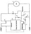
- the embodiment of the figure shows the use of Reverse polarity protection when powering an external or internally influenced inductive consumer 3.
- inductive For example, consumers can be a DC motor act of a fan, for example drives a cooling device in a motor vehicle.
- the Consumer can also use an external inductor Be supplied with electricity.
- the DC voltage source is Ubat formed by a vehicle battery.
- the consumer 3 will via a load current switch 4, which is an electronic Device 5 is controlled, powered.
- the electronic device 5 a speed control of the trained as a DC motor Consumer 3 are carried out.
- a speed control is known for example from DE 196 30 036 A1.
- the consumer 3 is the semiconductor component 2, which is a MOS field effect transistor or bipolar transistor can be in its low-resistance conductive state, so that the load current when the load current switch is turned off 4 does not suddenly become zero, but over the freewheel branch 1 continues to flow.
- the semiconductor component 2 which is a MOS field effect transistor or bipolar transistor can be in its low-resistance conductive state, so that the load current when the load current switch is turned off 4 does not suddenly become zero, but over the freewheel branch 1 continues to flow.
- the semiconductor device 2 In the event of a polarity reversal of the supply voltage Ubat the semiconductor device 2 is controlled in such a way that it comes into a high-resistance state. For example by the reverse polarity supply voltage, which over a resistor 7 the control electrode (gate) of the semiconductor component 2 controls. Because the source-drain path is high-impedance the polarity of the supply voltage flows Current through the consumer 3 and the load current switch 4 backwards to Ubat-, which is usually Ubat +. hereby the electronic device 5 before the negative Voltage protected.
- the electronic device 5 also supplied by the Ubat supply voltage. For this is the electronic device 5 via the source-drain path of the semiconductor component 2 connected to Ubat.
- the junction of the electronic device 5 is located I between the freewheeling diode 6 and the semiconductor device 2 in the freewheeling branch 1.
- the gate of the semiconductor component can be formed by a zener diode 10 2 are protected according to its source.
- a diode 9 and a zener diode 8 which with the gate of the semiconductor device are connected, the reverse polarity protection at a defines high negative voltage again conductive, which Interference peaks during polarity reversal, for example inductive switching operations, limited and in heat output be implemented.
- the Zener diode 8 operated in breakdown and the negative voltage kept on such a scale that they the Electronics do not damage. Voltage peaks therefore judge no damage to the electronics.
Landscapes
- Emergency Protection Circuit Devices (AREA)
- Electronic Switches (AREA)
- Semiconductor Integrated Circuits (AREA)
- Charge And Discharge Circuits For Batteries Or The Like (AREA)
Abstract
Description
- 1
- Freilaufzweig
- 2
- Halbleiterbauelement
- 3
- induktiver Verbraucher
- 4
- Laststromschalter
- 5
- elektronische Einrichtung
- 6
- Freilaufdiode
- 7
- ohmscher Widerstand
- 8
- Zenerdiode
- 9
- Diode
- 10
- Zenerdiode
Claims (10)
- Elektrische Schaltung zum Schutz einer an eine Gleichspannungsquelle Ubat angeschlossenen elektronischen Einrichtung (5) beim Verpolen der Gleichspannungsquelle mit einem beim Verpolen in einen hochohmigen Zustand steuerbares Bauelement (2), dadurch gekennzeichnet, dass das Bauelement (2) parallel zu einem von der Gleichspannungsquelle Ubat über einen Laststromkreis versorgten Verbraucher (3) geschaltet ist, so daß beim Verpolen der Strom zumindest teilweise über den Verbraucher (3) und den Laststromkreis fließt.
- Elektrische Schaltung nach Anspruch 1, dadurch gekennzeichnet, dass der Verbraucher (3) extern oder intern induktiv beeinflusst ist.
- Elektrische Schaltung nach Anspruch 1 oder 2, dadurch gekennzeichnet, dass das als steuerbarer Schalter ausgebildete Bauelement (2) in einem Freilaufzweig (1) des induktiven Verbrauchers (3) liegt.
- Elektrische Schaltung nach einem der Ansprüche 1 bis 3, dadurch gekennzeichnet, dass das in den hochohmigen Zustand steuerbare Bauelement (2) ein Halbleiterbauelement ist.
- Elektrische Schaltung nach ein der Ansprüche 1 bis 4, dadurch gekennzeichnet, dass das Bauelement (2) als bipolarer Transistor oder MOS-Feldeffektransistor ausgebildet ist.
- Elektrische Schaltung nach einem der Ansprüche 1 bis 5, dadurch gekennzeichnet, dass die elektronische Einrichtung (5) zur Drain-Source-Strecke des Halbleiterbauelements (2) in Reihe geschaltet ist.
- Elektrische Schaltung nach einem der Ansprüche 1 bis 6, dadurch gekennzeichnet, dass der Freilaufzweig (1) eine mit der Drain-Source-Strecke des Halbleiterbauelementes (2) in Reihe geschaltete Freilaufdiode (6) aufweist und dass die Verbindungsstelle mit der elektrischen Einrichtung (5) zwischen der Freilaufdiode (6) und dem Halbleiterbauelement (2) liegt.
- Elektrische Schaltung nach einem der Ansprüche 1 bis 7, dadurch gekennzeichnet, dass das elektronische Bauelement (2) durch die verpolte Gleichspannungsquelle Ubat in den hochohmigen Zustand gesteuert ist.
- Elektrische Schaltung nach einem der Ansprüche 1 bis 8, dadurch gekennzeichnet, dass oberhalb einer bestimmten hohen negativen Spannung das elektronische Bauelement (2) in den niederohmigen Zustand steuerbar ist.
- Elektrische Schaltung nach Anspruch 9, dadurch gekennzeichnet, dass mit dem Gate des elektronischen Halbleiterbauelements (2) eine Zenerdiode (8) über gegebenenfalls eine Diode (9) verbunden ist.
Priority Applications (1)
| Application Number | Priority Date | Filing Date | Title |
|---|---|---|---|
| EP20010102044 EP1227562B1 (de) | 2001-01-30 | 2001-01-30 | Elektrische Schaltung zum Schutz einer an eine Gleichspannungsquelle angeschlossenen elektronischen Einrichtung beim Verpolen der Gleichspannungsquelle |
Applications Claiming Priority (1)
| Application Number | Priority Date | Filing Date | Title |
|---|---|---|---|
| EP20010102044 EP1227562B1 (de) | 2001-01-30 | 2001-01-30 | Elektrische Schaltung zum Schutz einer an eine Gleichspannungsquelle angeschlossenen elektronischen Einrichtung beim Verpolen der Gleichspannungsquelle |
Publications (2)
| Publication Number | Publication Date |
|---|---|
| EP1227562A1 true EP1227562A1 (de) | 2002-07-31 |
| EP1227562B1 EP1227562B1 (de) | 2013-11-06 |
Family
ID=8176338
Family Applications (1)
| Application Number | Title | Priority Date | Filing Date |
|---|---|---|---|
| EP20010102044 Expired - Lifetime EP1227562B1 (de) | 2001-01-30 | 2001-01-30 | Elektrische Schaltung zum Schutz einer an eine Gleichspannungsquelle angeschlossenen elektronischen Einrichtung beim Verpolen der Gleichspannungsquelle |
Country Status (1)
| Country | Link |
|---|---|
| EP (1) | EP1227562B1 (de) |
Cited By (2)
| Publication number | Priority date | Publication date | Assignee | Title |
|---|---|---|---|---|
| DE102011011295A1 (de) | 2011-02-15 | 2012-08-16 | Hella Kgaa Hueck & Co. | Stromversorgungsanordnung für ohmsch-induktiven Verbraucher |
| FR2977403A1 (fr) * | 2011-07-01 | 2013-01-04 | Accumulateurs Fixes | Circuit de deconnexion pour batterie |
Citations (1)
| Publication number | Priority date | Publication date | Assignee | Title |
|---|---|---|---|---|
| DE19732094A1 (de) | 1997-07-25 | 1999-01-28 | Bosch Gmbh Robert | Steuerschaltung für einen Gleichstrommotor |
-
2001
- 2001-01-30 EP EP20010102044 patent/EP1227562B1/de not_active Expired - Lifetime
Patent Citations (1)
| Publication number | Priority date | Publication date | Assignee | Title |
|---|---|---|---|---|
| DE19732094A1 (de) | 1997-07-25 | 1999-01-28 | Bosch Gmbh Robert | Steuerschaltung für einen Gleichstrommotor |
Cited By (3)
| Publication number | Priority date | Publication date | Assignee | Title |
|---|---|---|---|---|
| DE102011011295A1 (de) | 2011-02-15 | 2012-08-16 | Hella Kgaa Hueck & Co. | Stromversorgungsanordnung für ohmsch-induktiven Verbraucher |
| DE102011011295B4 (de) | 2011-02-15 | 2026-04-30 | HELLA GmbH & Co. KGaA | Stromversorgungsanordnung für ohmsch-induktiven Verbraucher |
| FR2977403A1 (fr) * | 2011-07-01 | 2013-01-04 | Accumulateurs Fixes | Circuit de deconnexion pour batterie |
Also Published As
| Publication number | Publication date |
|---|---|
| EP1227562B1 (de) | 2013-11-06 |
Similar Documents
| Publication | Publication Date | Title |
|---|---|---|
| EP0423885B1 (de) | Stromversorgungseinrichtung mit Einschaltstrombegrenzungsschaltung | |
| EP1074081B1 (de) | Verpolschutzschaltung | |
| DE112009000142T5 (de) | Schaltung zur Ansteuerung einer induktiven Last | |
| EP0352659B1 (de) | Schaltungsanordnung zum Erfassen des Kurzschlusses einer mit einem FET in Reihe liegenden Last | |
| DE102009007790B3 (de) | Treiberchip zum Treiben einer induktiven Last | |
| DE2343912C3 (de) | Stromversorgungseinrichtung, insbesondere für ein Kraftfahrzeug | |
| AT408494B (de) | Schutzschaltung für ein elektronisches gerät | |
| DE102022202702A1 (de) | Elektronikeinheit für ein Elektrogerät | |
| EP3221943B1 (de) | Schutzschaltung für einen überspannungs- und/oder überstromschutz | |
| EP3381127A1 (de) | Schaltungsanordnung zur temperaturabhängigen ansteuerung eines schaltelementes | |
| EP1299933B1 (de) | Elektronische schaltung für ein energieversorgungsgerät, insbesondere für ein ladegerät für akkumulatoren | |
| DE3741394C2 (de) | Schaltungsanordnung zum Schutz vor Verpolungsschäden für Lastkreise mit einem MOS-FET als Schalttransistor | |
| DE102005037409A1 (de) | Start-Up Schalter um einer Anwendungsschaltung eine Start-Up Spannung zur Verfügung zu stellen | |
| EP0384937A1 (de) | Schutzschaltung für einen Leistungs-MOSFET | |
| DE102018117528A1 (de) | Entladeschaltungen zum Entladen von induktiven Elementen mit Temperaturschutz | |
| EP0259845B1 (de) | Verpolungs- und Wechselspannungsschutz für gleichstrombetriebene elektrische Verbraucher | |
| EP1227562B1 (de) | Elektrische Schaltung zum Schutz einer an eine Gleichspannungsquelle angeschlossenen elektronischen Einrichtung beim Verpolen der Gleichspannungsquelle | |
| DE10002875A1 (de) | Elektrische Schaltung zum Schutz einer an eine Gleichspannungsquelle angeschlossenen elektronischen Einrichtung beim Verpolen der Gleichspannungsquelle | |
| DE19805491C1 (de) | Diodenschaltung mit idealer Diodenkennlinie | |
| DE102013215820A1 (de) | Handwerkzeugakku mit einem Brückengleichrichter | |
| DE10048592B4 (de) | Verpolschutzschaltung | |
| DE102004052675A1 (de) | Gleichstromversorgungsschaltung und diese enthaltender Erdschluss-Schutzschalter | |
| DE19739999C2 (de) | Ansteuerschaltung für ein mittels Feldeffekt gesteuertes Leistungs-Halbleiterbauelement | |
| EP1193824A2 (de) | Gegenspannungsschutzschaltung | |
| DE10243571B4 (de) | Schaltungsanordnung zum Kurzschlussabschalten eines MOSFET-Schalters |
Legal Events
| Date | Code | Title | Description |
|---|---|---|---|
| PUAI | Public reference made under article 153(3) epc to a published international application that has entered the european phase |
Free format text: ORIGINAL CODE: 0009012 |
|
| AK | Designated contracting states |
Kind code of ref document: A1 Designated state(s): AT BE CH CY DE DK ES FI FR GB GR IE IT LI LU MC NL PT SE TR |
|
| AX | Request for extension of the european patent |
Free format text: AL;LT;LV;MK;RO;SI |
|
| 17P | Request for examination filed |
Effective date: 20030117 |
|
| AKX | Designation fees paid |
Designated state(s): DE FR GB IT SE |
|
| 17Q | First examination report despatched |
Effective date: 20090921 |
|
| GRAP | Despatch of communication of intention to grant a patent |
Free format text: ORIGINAL CODE: EPIDOSNIGR1 |
|
| RIC1 | Information provided on ipc code assigned before grant |
Ipc: H02H 11/00 20060101AFI20130417BHEP Ipc: H02H 9/04 20060101ALI20130417BHEP |
|
| INTG | Intention to grant announced |
Effective date: 20130517 |
|
| RAP1 | Party data changed (applicant data changed or rights of an application transferred) |
Owner name: HKR SEUFFER AUTOMOTIVE GMBH & CO. KG |
|
| GRAS | Grant fee paid |
Free format text: ORIGINAL CODE: EPIDOSNIGR3 |
|
| GRAA | (expected) grant |
Free format text: ORIGINAL CODE: 0009210 |
|
| AK | Designated contracting states |
Kind code of ref document: B1 Designated state(s): DE FR GB IT SE |
|
| REG | Reference to a national code |
Ref country code: GB Ref legal event code: FG4D Free format text: NOT ENGLISH |
|
| REG | Reference to a national code |
Ref country code: DE Ref legal event code: R096 Ref document number: 50116349 Country of ref document: DE Effective date: 20131224 |
|
| PG25 | Lapsed in a contracting state [announced via postgrant information from national office to epo] |
Ref country code: SE Free format text: LAPSE BECAUSE OF FAILURE TO SUBMIT A TRANSLATION OF THE DESCRIPTION OR TO PAY THE FEE WITHIN THE PRESCRIBED TIME-LIMIT Effective date: 20131106 |
|
| REG | Reference to a national code |
Ref country code: DE Ref legal event code: R082 Ref document number: 50116349 Country of ref document: DE Representative=s name: WINTER, BRANDL, FUERNISS, HUEBNER, ROESS, KAIS, DE |
|
| REG | Reference to a national code |
Ref country code: DE Ref legal event code: R082 Ref document number: 50116349 Country of ref document: DE Representative=s name: WINTER, BRANDL, FUERNISS, HUEBNER, ROESS, KAIS, DE |
|
| REG | Reference to a national code |
Ref country code: DE Ref legal event code: R097 Ref document number: 50116349 Country of ref document: DE |
|
| PLBE | No opposition filed within time limit |
Free format text: ORIGINAL CODE: 0009261 |
|
| STAA | Information on the status of an ep patent application or granted ep patent |
Free format text: STATUS: NO OPPOSITION FILED WITHIN TIME LIMIT |
|
| 26N | No opposition filed |
Effective date: 20140807 |
|
| GBPC | Gb: european patent ceased through non-payment of renewal fee |
Effective date: 20140206 |
|
| REG | Reference to a national code |
Ref country code: DE Ref legal event code: R097 Ref document number: 50116349 Country of ref document: DE Effective date: 20140807 |
|
| PG25 | Lapsed in a contracting state [announced via postgrant information from national office to epo] |
Ref country code: GB Free format text: LAPSE BECAUSE OF NON-PAYMENT OF DUE FEES Effective date: 20140206 |
|
| REG | Reference to a national code |
Ref country code: FR Ref legal event code: PLFP Year of fee payment: 16 |
|
| PGFP | Annual fee paid to national office [announced via postgrant information from national office to epo] |
Ref country code: IT Payment date: 20160128 Year of fee payment: 16 |
|
| PGFP | Annual fee paid to national office [announced via postgrant information from national office to epo] |
Ref country code: FR Payment date: 20160121 Year of fee payment: 16 |
|
| REG | Reference to a national code |
Ref country code: FR Ref legal event code: ST Effective date: 20170929 |
|
| PG25 | Lapsed in a contracting state [announced via postgrant information from national office to epo] |
Ref country code: FR Free format text: LAPSE BECAUSE OF NON-PAYMENT OF DUE FEES Effective date: 20170131 |
|
| PG25 | Lapsed in a contracting state [announced via postgrant information from national office to epo] |
Ref country code: IT Free format text: LAPSE BECAUSE OF NON-PAYMENT OF DUE FEES Effective date: 20170130 |
|
| REG | Reference to a national code |
Ref country code: DE Ref legal event code: R082 Ref document number: 50116349 Country of ref document: DE Representative=s name: WINTER, BRANDL, FUERNISS, HUEBNER, ROESS, KAIS, DE Ref country code: DE Ref legal event code: R081 Ref document number: 50116349 Country of ref document: DE Owner name: HKR AUTOMOTIVE GMBH, DE Free format text: FORMER OWNER: HKR SEUFFER AUTOMOTIVE GMBH & CO. KG, 74635 KUPFERZELL, DE Ref country code: DE Ref legal event code: R082 Ref document number: 50116349 Country of ref document: DE Representative=s name: WINTER, BRANDL - PARTNERSCHAFT MBB, PATENTANWA, DE |
|
| PGFP | Annual fee paid to national office [announced via postgrant information from national office to epo] |
Ref country code: DE Payment date: 20200121 Year of fee payment: 20 |
|
| REG | Reference to a national code |
Ref country code: DE Ref legal event code: R071 Ref document number: 50116349 Country of ref document: DE |