EP1227040A1 - Method and machine for packing reams of sheets - Google Patents
Method and machine for packing reams of sheets Download PDFInfo
- Publication number
- EP1227040A1 EP1227040A1 EP02001691A EP02001691A EP1227040A1 EP 1227040 A1 EP1227040 A1 EP 1227040A1 EP 02001691 A EP02001691 A EP 02001691A EP 02001691 A EP02001691 A EP 02001691A EP 1227040 A1 EP1227040 A1 EP 1227040A1
- Authority
- EP
- European Patent Office
- Prior art keywords
- ream
- packing material
- sheet
- conveyor
- faces
- Prior art date
- Legal status (The legal status is an assumption and is not a legal conclusion. Google has not performed a legal analysis and makes no representation as to the accuracy of the status listed.)
- Granted
Links
- 238000012856 packing Methods 0.000 title claims abstract description 91
- 238000000034 method Methods 0.000 title claims abstract description 36
- 239000000463 material Substances 0.000 claims abstract description 74
- 238000011144 upstream manufacturing Methods 0.000 claims description 11
- 238000006073 displacement reaction Methods 0.000 claims description 3
- 230000007306 turnover Effects 0.000 claims 1
- 239000000853 adhesive Substances 0.000 description 6
- 230000001070 adhesive effect Effects 0.000 description 6
- 230000001133 acceleration Effects 0.000 description 3
- 238000010438 heat treatment Methods 0.000 description 2
- 230000000284 resting effect Effects 0.000 description 2
- 238000010409 ironing Methods 0.000 description 1
- 230000003014 reinforcing effect Effects 0.000 description 1
- 230000000717 retained effect Effects 0.000 description 1
Images


Classifications
-
- B—PERFORMING OPERATIONS; TRANSPORTING
- B65—CONVEYING; PACKING; STORING; HANDLING THIN OR FILAMENTARY MATERIAL
- B65B—MACHINES, APPARATUS OR DEVICES FOR, OR METHODS OF, PACKAGING ARTICLES OR MATERIALS; UNPACKING
- B65B35/00—Supplying, feeding, arranging or orientating articles to be packaged
- B65B35/56—Orientating, i.e. changing the attitude of, articles, e.g. of non-uniform cross-section
- B65B35/58—Turning articles by positively-acting means, e.g. to present labelled portions in uppermost position
-
- B—PERFORMING OPERATIONS; TRANSPORTING
- B65—CONVEYING; PACKING; STORING; HANDLING THIN OR FILAMENTARY MATERIAL
- B65B—MACHINES, APPARATUS OR DEVICES FOR, OR METHODS OF, PACKAGING ARTICLES OR MATERIALS; UNPACKING
- B65B11/00—Wrapping, e.g. partially or wholly enclosing, articles or quantities of material, in strips, sheets or blanks, of flexible material
- B65B11/06—Wrapping articles, or quantities of material, by conveying wrapper and contents in common defined paths
- B65B11/08—Wrapping articles, or quantities of material, by conveying wrapper and contents in common defined paths in a single straight path
- B65B11/10—Wrapping articles, or quantities of material, by conveying wrapper and contents in common defined paths in a single straight path to fold the wrappers in tubular form about contents
- B65B11/12—Wrapping articles, or quantities of material, by conveying wrapper and contents in common defined paths in a single straight path to fold the wrappers in tubular form about contents and then to form closing folds of similar form at opposite ends of the tube
-
- B—PERFORMING OPERATIONS; TRANSPORTING
- B65—CONVEYING; PACKING; STORING; HANDLING THIN OR FILAMENTARY MATERIAL
- B65B—MACHINES, APPARATUS OR DEVICES FOR, OR METHODS OF, PACKAGING ARTICLES OR MATERIALS; UNPACKING
- B65B11/00—Wrapping, e.g. partially or wholly enclosing, articles or quantities of material, in strips, sheets or blanks, of flexible material
- B65B11/06—Wrapping articles, or quantities of material, by conveying wrapper and contents in common defined paths
- B65B11/38—Wrapping articles, or quantities of material, by conveying wrapper and contents in common defined paths in a combination of straight and curved paths
- B65B11/40—Wrapping articles, or quantities of material, by conveying wrapper and contents in common defined paths in a combination of straight and curved paths to fold the wrappers in tubular form about contents
- B65B11/42—Wrapping articles, or quantities of material, by conveying wrapper and contents in common defined paths in a combination of straight and curved paths to fold the wrappers in tubular form about contents and then to form closing folds of similar form at opposite ends of the tube
-
- B—PERFORMING OPERATIONS; TRANSPORTING
- B65—CONVEYING; PACKING; STORING; HANDLING THIN OR FILAMENTARY MATERIAL
- B65B—MACHINES, APPARATUS OR DEVICES FOR, OR METHODS OF, PACKAGING ARTICLES OR MATERIALS; UNPACKING
- B65B25/00—Packaging other articles presenting special problems
- B65B25/14—Packaging paper or like sheets, envelopes, or newspapers, in flat, folded, or rolled form
Definitions
- the present invention relates to a method of packing reams of sheets.
- the present invention relates to a method of packing reams of sheets of paper, to which the following description refers purely by way of example.
- a ream of sheets of paper comprises rectangular sheets of paper stacked and aligned to form a rectangular-base prism having two base faces defined by two opposite end sheets in the ream; two opposite lateral faces perpendicular to the base faces, i.e. two faces adjacent to the major sides of the base faces; and two opposite end faces perpendicular to the base faces and lateral faces, i.e. two faces adjacent to the minor sides of the base faces.
- Known methods of packing reams of sheets of paper are normally based on the principle of folding a sheet of packing material about a ream to form a tubular package enclosing the ream and having two opposite projecting portions projecting from the end faces; and folding the projecting portions on to the respective end faces.
- one known method of packing reams of sheets of paper comprises feeding a ream along a given path in a first feed direction parallel to the base faces; arresting the ream of sheets of paper to feed it in a second direction perpendicular to the base faces; placing a sheet of packing material perpendicular to the second direction, i.e. parallel to the base faces; and folding the sheet of packing material into a U about the ream by means of a folding spindle as the ream is fed in the second direction.
- the ream is arrested to form the tubular package by means of movable folding devices.
- the above method has the drawback of subjecting the reams without the sheets of packing material to severe acceleration when switching from the first to the second direction. Rapid acceleration in different directions tends to reduce friction between the sheets in the ream and to disarrange the stack, also in view of the fact that the ream is accelerated without the sheet of packing material, which, when partly folded, contributes towards keeping the sheets in the ream aligned. As a result, acceleration of the ream must be kept as low as possible, thus greatly reducing the output of the packing machine implementing the above method.
- each ream is defined by sheets stacked to form a rectangular-base prism of a given height, and comprises two base faces defined by respective end sheets in said ream, two lateral faces perpendicular to the base faces, and two end faces; the method comprising feeding said ream along a given path by means of a feed unit, placing a sheet of packing material along the path of the ream by means of a supply unit for supplying sheets of packing material, and conveying the ream and the sheet of packing material through a folding spindle to form a U-shaped fold; the method being characterized by pushing said ream in a feed direction parallel to said base faces, and placing said sheet of packing material crosswise to said feed direction.
- the present invention also relates to a machine for packing reams of sheets.
- a machine for packing reams of sheets wherein each ream is defined by sheets stacked to form a rectangular-base prism of a given height, and comprises two base faces defined by respective end sheets in said ream, two lateral faces perpendicular to the base faces, and two end faces;
- the machine comprising a feed unit for feeding said ream along a given path, a supply unit for supplying sheets of packing material and for placing a sheet of packing material along the path of the ream, and a folding spindle located along the path to fold the sheet of packing material into a U about said ream;
- said feed unit comprises a first conveyor for pushing said ream, at said folding spindle, in a feed direction parallel to said base faces; and said supply unit comprising a conveying device for keeping said sheet of packing material crosswise to the feed direction at said folding spindle.
- Number 1 in Figure 1 indicates as a whole a machine for packing reams 2 of sheets 3 of paper in respective sheets 4 of packing material to form packs 5, one of which is shown in Figure 13.
- each ream 2 comprises a number of sheets 3 stacked and aligned to form a ream 2 in the form of a rectangular-base prism of height H.
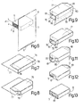
- Ream 2 comprises two opposite parallel base faces 6, each defined by an end sheet 3 in ream 2, and only one of which is shown in Figure 6; two parallel lateral faces 7 facing each other and perpendicular to base faces 6; and two parallel end faces 8 facing each other and perpendicular to base faces 6. Only one of lateral faces 7 and one of end faces 8 are shown in Figure 6.
- the rectangular-prism shape of ream 2 depends on the alignment of sheets 3, which contact one another and are kept aligned by the friction between adjacent sheets 3 in ream 2 when the forces acting on ream 2 are within given values.
- machine 1 comprises a frame 9, which supports a feed unit 10 for feeding reams 2 and packs 5 along a path P, a supply unit 11 for supplying sheets 4 of packing material to a packing station located along path P, and folding members indicated and described in detail later on.
- Feed unit 10 comprises a series of conveyors 12, 13, 14, 15, 16, 17 : conveyor 12 provides for supplying reams 2; conveyor 17 for removing packs 5; and conveyors 13, 14, 15 and 16 for feeding ream 2 and respective sheet 4 of packing material past said folding members. Conveyors 12, 13, 14, 15, 16, 17 are adjacent to one another and aligned in a horizontal direction D1 parallel to path P.
- Supply unit 11 comprises an unwinding device 18 for unwinding two strips 19 off respective reels 20; a cut-off device 21 for cutting sheets 4 off one of strips 19; and a conveying device 22 for conveying sheets 4 and placing each sheet 4 in a given position with respect to feed unit 10 and a respective ream 2.
- conveyor 12 comprises a conveyor 23 with belts looped about pulleys 24 (only one shown in Figures 1 and 2), and has a work branch 25 on which a base face 6 of each ream 2 rests.
- Conveyor 13 comprises a conveyor 26 with belts looped about pulley 24 and a pulley 27 to define a work branch 28 coplanar with work branch 25.
- Conveyor 13 also comprises two belt conveyors 29 located on opposite sides of conveyor 26, and each of which comprises a belt 30 looped about two pulleys 31 rotating about vertical axes, and has a work branch 32 perpendicular to work branch 28.
- Belts 30 of belt conveyors 29 are spaced apart so as to contact the end faces 8 of each ream 2 along respective work branches 32, and comprise projections 33 which, in use, contact lateral faces 7 at the edges formed by lateral faces 7 and end faces 8.
- Conveyor 14 is located downstream from conveyor 13 and conveying device 22 - for conveying sheets 4 of packing material and which extends partly between conveyors 13 and 14 - and comprises two belt conveyors 34 located one over the other to convey reams 2 and respective sheets 4 of packing material folded into a U about reams 2.
- Belt conveyors 34 have respective belts 35 looped about pulleys 36; and respective parallel, facing work branches 37 spaced apart by a distance substantially equal to height H of reams 2.
- Conveyor 15 comprises a drum 38 rotating about a horizontal axis 39 perpendicular to direction D1, and supporting two belt conveyors 40, each comprising a belt 41 looped about pulleys 42.
- Belts 41 have respective projections 43 parallel to axis 39, are operated in time with each other, and define respective facing work branches 44 spaced apart by a distance substantially equal to height H of ream 2.
- Conveyor 16 comprises two belt conveyors 45 located one over the other and having respective belts 46 looped about pulleys 47, and respective parallel, facing work branches 48 spaced apart by a distance substantially equal to height H of reams 2.
- a drum 49 is located at the output of the bottom belt conveyor 45, rotates about an axis 50 parallel to axis 39, has a heating body 51 along its outer surface, and is located between belt conveyor 45 and conveyor 17, which removes packs 5.
- unwinding device 18 comprises two vertical pins 52 (only one shown in Figure 1) supporting respective reels 20 of strips 19; two drive rollers 53; and rollers 54 for guiding the strips 19 unwound off respective reels 20 along respective unwinding paths converging towards rollers 53.
- Strips 19 are unwound alternately off respective reels 20 to change over from one reel 20 to the other. That is, as one strip 19 is unwound off one reel 20, the other reel 20 can be taken off the idle pin 52 and replaced with a new reel 20.
- Cut-off device 21 is adjacent to rollers 53 and comprises a fixed blade 55 located along the path of strip 19; and a vertical-axis drum 56 having a blade 57 located along the periphery of drum 56 and rotated in time with strip 19 to cooperate with blade 55 and cut a sheet 4 of packing material off strip 19.
- Conveying device 22 for conveying sheet 4 of packing material is adjacent to cut-off device 21, and comprises four belt conveyors 58 divided into two pairs 59 of conveyors 58, located one over and the other beneath ream feed unit 10 and conveyors 13 and 14, to grip sheet 4 or strip 19 at opposite ends.
- Each pair 59 of conveyors 58 has two adjacent work branches 60 for gripping and simultaneously feeding forward a sheet 4 of packing material or strip 19. That is, conveyors 58 feed strip 19 forward and support the free end of strip 19 until sheet 4 is cut off strip 19.
- Conveying device 22 also comprises a guide 61 comprising two parallel, facing plates 62 and 63 spaced a small distance apart to form a gap, which is engaged by sheet 4 of packing material or by strip 19 until sheet 4 is cut off strip 19.
- An opening 64 of a length substantially equal to height H of reams 2, is formed in plates 62 and 63 at conveyors 13 and 14; plate 62 is connected to a further two plates 65 and 66 parallel to work branch 28; plate 65 is comb-shaped and inserted between the belts of conveyor 26; and plate 66 is located over plate 65 and separated from plate 65 by a distance substantially equal to height H of reams 2.
- Plate 63 has two free edges 67 defining the top and bottom of opening 64 and, in fact, a folding spindle for folding sheet 4 about ream 2, so that device 22 for conveying sheets 4 of packing material defines one of the folding members referred to previously.
- the folding members also comprise two fixed folding devices 68 located along path P at conveyor 14; a plate 69 between conveyors 15 and 16; and three pairs of fixed folding devices 70, 71, 72 located successively along path P at conveyor 16.
- Feed unit 10 for feeding reams 2 and packs 5 comprises reinforcing plates 73 extending along, and for preventing deformation of, respective work branches 25, 37, 48 of conveyors 12, 14, 16; and bars 74 located at the crossover points between conveyors 14 and 15 and conveyors 15 and 16.
- Bars 74 provide for filling the gaps formed by the curve of pulleys 36, 42, 47 at the crossover points between conveyors 14, 15, 16, and also act partly as folding members. That is, each gap is filled by two adjacent bars 74, each integral with one of two adjacent conveyors 14, 15 and 15, 16, so that bars 74 fold sheet 4 of packing material as ream 2 and sheet 4 of packing material are turned over by conveyor 15. That is, bars 74 act as folding members upon relative displacement, crosswise to direction D1, of adjacent conveyors 14, 15, 16.
- Machine 1 also comprises two gumming devices 75 located along conveyor 16 to apply two bands S of adhesive to sheets 4 of packing material.
- a ream 2 is fed by conveyor 12 along path P, rests on work branch 25 of conveyor 12 along a base face 6 hereinafter referred to as the supporting base face 6, and is positioned with lateral faces 7 perpendicular to feed direction D1. End faces 8 are therefore positioned parallel to feed direction D1, and the base face 6 opposite the supporting base face 6 is hereinafter referred to as the top base face 6.
- reams 2 are fed from left to right, so the two lateral faces 7 of each ream 2 located to the left and right in feed direction D1 in the accompanying drawings are hereinafter referred to as the upstream and downstream lateral face 7 respectively.
- Conveyor 12 transfers ream 2 to conveyor 13, which feeds ream 2, resting on work branch 28 of belt conveyor 26, in direction P, while laterally engaging end faces 8 by means of work branches 32 of belt conveyors 29, and at the same time positioning projections 33 in contact with lateral faces 7 to prevent any disarrangement of ream 2 in direction D1.
- Conveying device 22 feeds a sheet 4 of packing material along guide 61 into the position shown in Figure 6 with respect to ream 2.
- Sheet 4 of packing material has a band A of adhesive, which is inactive and which is activated by heat when the package is completed.
- Conveyor 13 then pushes ream 2 - partly by means of belt conveyor 26 and partly by means of projections 33 on belt conveyors 29 pushing the upstream lateral face 7 - through opening 64 to engage sheet 4 of packing material, which is folded into a U by the free edges 67 of plate 63, i.e. by the folding spindle indicated by the same reference number 67 as the edges of plate 63.
- ream 2 is retained by belts 30 and projections 33.
- the U-folded sheet 4 of packing material adheres to the downstream face 7 in direction D1, and has a portion 76 having a free portion on the top base face 6, and a portion 77 partly contacting the supporting base face 6 and partly projecting with respect to the upstream lateral face 7.
- Sheet 4 of packing material also has two tabs 78 projecting with respect to the downstream lateral face 7, and which are folded on to end faces 8 ( Figure 8) by folding devices 68 located at conveyor 14 ( Figures 2 and 3).
- Conveyor 14 keeps portions 76 and 77 in contact with base faces 6 by means of belts 35 along work branches 37 of belt conveyors 34, and transfers ream 2 and sheet 4 of packing material to conveyor 15 between the two conveyors 40 aligned with conveyors 32. That is, ream 2 and the U-folded sheet 4 of packing material are gripped between the two belt conveyors 34 to hold sheet 4 of packing material in position and increase friction between sheets 3 in ream 2.
- Portion 77 is folded on to lateral face 7 (upstream before rotation, and downstream after rotation, of the drum).
- the bottom bar 74 associated with conveyor 14 makes a fold at the edge formed by the supporting base face 6 and the upstream lateral face 7; and, with reference to Figure 4, as the drum completes its rotation, said fold is gone over again by folding device 69 and the bottom bar 74 associated with conveyor 16.
- the bottom bar 74 associated with conveyor 16 provides for ironing portion 77 so that it adheres partly to the downstream lateral face 7 (as the drum completes its rotation).
- the sheet folded partly about ream 2 has a portion 79 projecting downwards; two lateral tabs 80 projecting on opposite sides with respect to end faces 8 at the downstream lateral face 7; and two pairs of tabs 81 projecting with respect to end faces 8 at respective base faces 6.
- Ream 2 and sheet 4 of packing material are then fed past fixed folding device 71, which a helical folding device for folding the two bottom tabs 81 squarely on to end faces 8 ( Figure 12), while gumming devices 75 apply respective bands S of adhesive to the two top tabs 81, which are folded on to end faces 8 and bottom tabs 81 and sealed to bottom tabs 81 by bands S of adhesive to form the Figure 13 pack 5, which is removed by conveyor 17.
- pack 5 is transferred from conveyor 16 to conveyor 17, roller 49 is brought into contact with pack 5 and brings heating body 51 into contact with portion 79, at the portion of sheet 4 of packing material bearing strip A of adhesive, to activate the adhesive and seal portion 79 to portion 76.
Landscapes
- Engineering & Computer Science (AREA)
- Mechanical Engineering (AREA)
- Basic Packing Technique (AREA)
- Packaging Of Special Articles (AREA)
- Auxiliary Devices For And Details Of Packaging Control (AREA)
- Folding Of Thin Sheet-Like Materials, Special Discharging Devices, And Others (AREA)
- Control And Other Processes For Unpacking Of Materials (AREA)
- Packages (AREA)
- Supplying Of Containers To The Packaging Station (AREA)
- Buffer Packaging (AREA)
- Wrapping Of Specific Fragile Articles (AREA)
- Sheets, Magazines, And Separation Thereof (AREA)
- Containers And Plastic Fillers For Packaging (AREA)
Abstract
Description
Claims (25)
- A method of packing reams of sheets, wherein each ream (2) is defined by sheets (3) stacked to form a rectangular-base prism of a given height (H), and comprises two base faces (6) defined by respective end sheets (3) in said ream (2), two lateral faces (7) perpendicular to the base faces (6), and two end faces (8); the method comprising feeding said ream (2) along a given path (P) by means of a feed unit (10), placing a sheet (4) of packing material along the path (P) of the ream (2) by means of a supply unit for supplying sheets (4) of packing material, and conveying the ream (2) and the sheet (4) of packing material through a folding spindle (67) to form a U-shaped fold; the method being characterized by pushing said ream (2) in a feed direction (D1) parallel to said base faces (6), and placing said sheet (4) of packing material crosswise to said feed direction (D1).
- A method as claimed in Claim 1, characterized by placing said sheet (4) of packing material parallel to said lateral faces (7) of the ream (2).
- A method as claimed in Claim 2, characterized by feeding said ream (2) and said sheet (4) of packing material through said spindle (67) by means of first push members (33) of said feed unit (10), which act on the lateral face (7) located upstream with respect to the feed direction (D1).
- A method as claimed in Claim 3, characterized by feeding said ream (2) and the sheet (4) of packing material through said spindle (67) by means of a first conveyor (13) forming part of said feed unit (10) and comprising two first belt conveyors (29) having respective belts (30) contacting the end faces (8) along respective work branches (32).
- A method as claimed in any one of the foregoing Claims, characterized by conveying said ream (2) and said sheet (4) of packing material, folded partly about the ream (2), by means of adjacent further conveyors (14, 15, 16).
- A method as claimed in Claim 5, characterized by gripping the ream (2) and the partly folded sheet (4) of packing material between opposite parallel further belts (35, 41, 46) of each of the further conveyors (14, 15, 16).
- A method as claimed in Claim 5 or 6, characterized by folding the sheet (4) of packing material about said ream (2) as they are fed between said further conveyors (14, 15, 16).
- A method as claimed in Claim 7, characterized by folding a portion (77) of the sheet (4) of packing material into an L by means of a relative displacement of said further conveyors (14, 15, 16); said relative displacement being crosswise to said feed direction (D1).
- A method as claimed in Claim 8, characterized by turning over one of said further conveyors (14, 15, 16), together with the ream (2) and the sheet (4) of packing material, about an axis (39) perpendicular to said feed direction (D1) to fold said portion (77) of the sheet (4) of packing material into an L.
- A method as claimed in Claim 9, characterized in that said axis (39) is perpendicular to the end faces (8).
- A method as claimed in Claim 10, characterized by turning said ream (2) and the respective sheet (4) of packing material over through 180° about said axis (39) to invert the position of the base faces (6) and of the lateral faces (7) with respect to the feed direction (D1).
- A method as claimed in any one of Claims 8 to 11, characterized in that said further conveyors (14, 15, 16) comprise a second conveyor (15) located between two of said further conveyors (14, 16) and comprising two second belt conveyors (40) to grip the ream (2) and the sheet (4) of packing material between said second belt conveyors (40); the method providing for turning over said ream (2) and said sheet (4) of packing material by rotating the two second belt conveyors (40) about said axis (39).
- A method as claimed in one of Claims 8 to 11, characterized in that said further conveyors (14, 15, 16) comprise bars (74) located at the crossover points between said further conveyors (14, 15, 16); the method providing for positioning the upstream lateral face (7) flush with the bars (74) associated with the turn-over conveyor (15).
- A method as claimed in any one of the foregoing Claims, characterized by folding said sheet (4) of packing material about said ream (2) to form a tubular package about the base faces (6) and the lateral faces (7); and folding tabs (78, 80, 81), projecting with respect to the end faces (8), squarely on to the end faces (8) solely by means of fixed folding devices (67, 68, 69, 70, 71, 72, 74) located along the path (P) of the ream (2).
- A machine for packing reams of sheets, wherein each ream (2) is defined by sheets (3) stacked to form a rectangular-base prism of a given height (H), and comprises two base faces (6) defined by respective end sheets (3) in said ream (2), two lateral faces (7) perpendicular to the base faces (6), and two end faces (8); the machine comprising a feed unit (10) for feeding said ream (2) along a given path (P), a supply unit (11) for supplying sheets (4) of packing material and for placing a sheet (4) of packing material along the path (P) of the ream (2), and a folding spindle (67) located along the path (P) to fold the sheet (4) of packing material into a U about said ream (2); the machine being characterized in that said feed unit (10) comprises a first conveyor (13) for pushing said ream (2), at said folding spindle (67), in a feed direction (D1) parallel to said base faces (6); and said supply unit (11) comprising a conveying device (22) for keeping said sheet (4) of packing material crosswise to the feed direction (D1) at said folding spindle (67).
- A machine as claimed in Claim 15, characterized in that said first conveyor (13) comprises push members (33) acting on the lateral face (7) upstream with respect to the feed direction (D1) of the ream (2); said conveying device (22) keeping said sheet (4) of packing material parallel to and facing the downstream lateral face (7).
- A machine as claimed in Claim 16, characterized in that said conveying device comprises a guide (61) comprising a first and a second plate (62, 63) having an opening (64) permitting passage of said ream (2); said folding spindle (67) being defined by the free edges (67) of said second plate (63) at said opening (64).
- A machine as claimed in Claim 16 or 17, characterized in that said first conveyor (13) comprises two first belt conveyors (29) comprising respective belts (30) extending along respective work branches (32) and which contact the end faces (8) of the ream (2).
- A machine as claimed in Claim 18, characterized in that said push members (33) are projections (33) located along said belts (30).
- A machine as claimed in any one of Claims 15 to 19, characterized by comprising adjacent further conveyors (14, 15, 16) for feeding said ream (2) and said sheet (4) of packing material, folded partly about the ream (2), along said path (P) in said feed direction (D1); each further conveyor (14, 15, 16) comprising two further conveying devices (34, 40, 45) parallel to and facing each other to grip the ream (2) and the sheet (4) of packing material folded partly about the ream (2).
- A machine as claimed in Claim 20, characterized in that said further conveying devices (34, 40, 45) are belt conveyors.
- A machine as claimed in Claim 20 or 21, characterized by comprising folding members (68, 69, 70, 71, 72, 74) located along the path (P), at said further conveyors (14, 15, 16), to fold the sheet (4) of packing material about said ream (2).
- A machine as claimed in Claim 22, characterized in that said further conveyors (14, 15, 16) comprise a second conveyor (15) comprising a drum (38) rotating about an axis (39) perpendicular to said feed direction (D1) to fold the sheet (4) of packing material into an L about the ream (2) by means of fixed folding members (60, 74).
- A machine as claimed in Claim 23, characterized in that the drum (38) supports two second belt conveyors (40) parallel to and facing each other to grip the ream (2) and the sheet (4) of packing material, and to turn said ream (2) and the respective sheet (4) of packing material over through 180° about said axis (39) to invert the position of the base faces (6) and of the lateral faces (7) with respect to the feed direction (D1).
- A machine as claimed in Claim 24, characterized in that said further conveyors (14, 15, 16) comprise a third conveyor (14) located directly upstream from said second conveyor (15), and a fourth conveyor (16) located directly downstream from the second conveyor (15); the feed unit (10) comprising bars (74) extending transversely with respect to the feed direction (D1), associated with each further conveyor (14, 15, 16), and located at the crossover points between said further conveyors (14, 15, 16) to fold a portion (77) of said sheet (4) of packing material into an L as said second belt conveyors (40) are rotated.
Priority Applications (1)
| Application Number | Priority Date | Filing Date | Title |
|---|---|---|---|
| EP04002812A EP1477404B1 (en) | 2001-01-26 | 2002-01-24 | Device for packing a product |
Applications Claiming Priority (2)
| Application Number | Priority Date | Filing Date | Title |
|---|---|---|---|
| ITTO010075 | 2001-01-26 | ||
| IT2001TO000075A ITTO20010075A1 (en) | 2001-01-26 | 2001-01-26 | METHOD AND WRAPPING MACHINE OF SHEETS. |
Related Child Applications (1)
| Application Number | Title | Priority Date | Filing Date |
|---|---|---|---|
| EP04002812A Division EP1477404B1 (en) | 2001-01-26 | 2002-01-24 | Device for packing a product |
Publications (2)
| Publication Number | Publication Date |
|---|---|
| EP1227040A1 true EP1227040A1 (en) | 2002-07-31 |
| EP1227040B1 EP1227040B1 (en) | 2005-12-14 |
Family
ID=11458460
Family Applications (2)
| Application Number | Title | Priority Date | Filing Date |
|---|---|---|---|
| EP02001691A Expired - Lifetime EP1227040B1 (en) | 2001-01-26 | 2002-01-24 | Method and machine for packing reams of sheets |
| EP04002812A Expired - Lifetime EP1477404B1 (en) | 2001-01-26 | 2002-01-24 | Device for packing a product |
Family Applications After (1)
| Application Number | Title | Priority Date | Filing Date |
|---|---|---|---|
| EP04002812A Expired - Lifetime EP1477404B1 (en) | 2001-01-26 | 2002-01-24 | Device for packing a product |
Country Status (10)
| Country | Link |
|---|---|
| US (1) | US6640522B2 (en) |
| EP (2) | EP1227040B1 (en) |
| JP (2) | JP3774152B2 (en) |
| CN (1) | CN1227138C (en) |
| AT (2) | ATE333412T1 (en) |
| BR (1) | BR0200232A (en) |
| DE (2) | DE60207901T2 (en) |
| DK (1) | DK1227040T3 (en) |
| ES (2) | ES2254537T3 (en) |
| IT (1) | ITTO20010075A1 (en) |
Cited By (8)
| Publication number | Priority date | Publication date | Assignee | Title |
|---|---|---|---|---|
| EP1389592A1 (en) * | 2002-08-13 | 2004-02-18 | Innopack S.r.l. | A device for conveying stacks of sheets of paper or the like |
| WO2006041435A1 (en) | 2004-09-21 | 2006-04-20 | C.G. Bretting Manufacturing Company, Inc. | Bander apparatus and method of using same |
| WO2007046126A1 (en) | 2005-10-20 | 2007-04-26 | Kpl Packaging S.P.A. | Method and machine for packing groups of products arranged in one or more layers |
| WO2008074325A1 (en) * | 2006-12-20 | 2008-06-26 | Schur Packaging Systems A/S | Method and apparatus for wrapping a stack with a wrapping sheet |
| WO2008096386A1 (en) * | 2007-02-07 | 2008-08-14 | Kpl Packaging S.P.A. | Machine and method for packaging groups of products with dual heat-sealing system |
| US10717556B2 (en) | 2015-06-24 | 2020-07-21 | Ferag Ag | Method for producing collections of printed products, and device for carrying out said method |
| WO2021018587A1 (en) * | 2019-08-01 | 2021-02-04 | Khs Gmbh | Device and method for forming bundles of individual packages |
| WO2024205473A1 (en) * | 2023-03-31 | 2024-10-03 | Valmet Ab | Folding apparatus |
Families Citing this family (22)
| Publication number | Priority date | Publication date | Assignee | Title |
|---|---|---|---|---|
| US20030190474A1 (en) * | 2002-04-05 | 2003-10-09 | Nowak Michael R. | High strength film ream wrap |
| US20040253469A1 (en) * | 2002-12-30 | 2004-12-16 | Arent Wendy L. | Static of COF differential poly film ream wrap |
| WO2004060777A2 (en) * | 2002-12-31 | 2004-07-22 | Shuttleworth, Inc. | Compression passing roller |
| DE102004046576A1 (en) * | 2004-09-23 | 2006-03-30 | Focke & Co.(Gmbh & Co. Kg) | Device for wrapping groups of packages |
| ITBO20050698A1 (en) * | 2005-11-17 | 2007-05-18 | Kpl Packaging Spa | METHOD AND MACHINE FOR PACKAGING GROUPS OF PRODUCTS ORDERED ON ONE OR MORE LAYERS |
| ATE446905T1 (en) * | 2006-05-26 | 2009-11-15 | Mtc Macchine Trasformazione | PAPER FEEDING DEVICE FOR A STRAPPING MACHINE FOR PRODUCING PAPER ROLLS |
| US9346216B2 (en) * | 2007-06-08 | 2016-05-24 | International Paper Company | Easy-opening ream wrap |
| JP2009083962A (en) * | 2007-09-28 | 2009-04-23 | Canon Inc | Sheet processing apparatus and image forming apparatus |
| CN100493998C (en) * | 2007-11-21 | 2009-06-03 | 林高 | Transfer printing paper packing machine |
| DE102008052633A1 (en) * | 2008-10-22 | 2010-04-29 | Khs Ag | Method and device for producing a packaging unit |
| ES2353173B1 (en) | 2009-04-22 | 2011-11-23 | Dª OKSANA KYFYUK | DISPENSING COVER, SPECIFICALLY APPLICABLE TO CONTAINERS FOR FOOD SUPPLY. |
| DE102009037667B4 (en) * | 2009-08-14 | 2022-02-03 | Alpma Alpenland Maschinenbau Gmbh | Process for packaging products |
| US8568842B2 (en) | 2010-12-28 | 2013-10-29 | International Paper Company | Film for wrapping, methods of making and using |
| US8650843B2 (en) | 2011-02-04 | 2014-02-18 | Alpma Alpenland Maschinenbau Gmbh | Method of packaging products |
| DE102011018839A1 (en) * | 2011-04-27 | 2012-10-31 | Winkler + Dünnebier Gmbh | Process for packaging products and packaging equipment for carrying out the process |
| US20190047731A1 (en) * | 2017-08-12 | 2019-02-14 | Kretchman Holdings, LLC | Utensil Wrapping Apparatus |
| CN109823620B (en) * | 2019-03-20 | 2023-12-15 | 深圳市联欣科技有限公司 | Automatic film folding, winding and buckling equipment |
| CN109896086B (en) * | 2019-03-20 | 2024-01-09 | 深圳市联欣科技有限公司 | Film buckling structure |
| JP7680247B2 (en) * | 2021-04-02 | 2025-05-20 | 日本製紙株式会社 | packaging equipment |
| NL2029342B1 (en) * | 2021-10-07 | 2023-04-19 | Buhrs Packaging Solutions B V | A wrapping module and a method for providing a sleeve around a mail item |
| CN117416569B (en) * | 2023-11-08 | 2025-09-12 | 江苏洁丽莱科技有限公司 | A fully automatic high-speed double-block heat shrink soap packaging machine |
| CN121247143B (en) * | 2025-12-05 | 2026-02-17 | 温州核成科技有限公司 | An automatic strapping device |
Citations (5)
| Publication number | Priority date | Publication date | Assignee | Title |
|---|---|---|---|---|
| DE947538C (en) * | 1948-08-10 | 1956-08-16 | Mach Automatiques Bardet | Machine for packing several similar, stacked bodies |
| DE1101266B (en) * | 1954-09-17 | 1961-03-02 | Nekoosa Edwards Paper Company | Packaging machine, in particular for wrapping stacks of paper |
| US3996728A (en) * | 1974-12-13 | 1976-12-14 | Vittorio Gentili | Apparatus for wrapping paper reams and the like in sheets cut off a continuous packing web and for adjusting the size of such sheets according to the ream size |
| US4517785A (en) * | 1982-02-08 | 1985-05-21 | Shin Nihon Machine Manufacturing Co., Ltd. | Automatic confectionary-and-likes manufacturing equipment |
| EP0515320A1 (en) * | 1991-05-24 | 1992-11-25 | WRAPMATIC S.p.A. | A method of wrapping reams of paper, and equipment for the implementation of such a method |
Family Cites Families (18)
| Publication number | Priority date | Publication date | Assignee | Title |
|---|---|---|---|---|
| US1458977A (en) * | 1920-09-03 | 1923-06-19 | Escobales Co Inc H | Package structure and method of making the same |
| GB227764A (en) * | 1924-09-17 | 1925-01-22 | William Rose | Improvements in, or relating to, apparatus or machines for wrapping, or applying labels to, caramels, blocks, packages, or the like |
| GB341411A (en) * | 1929-08-08 | 1931-01-08 | Package Machinery Co | Improvements in wrapping machines |
| US2192683A (en) * | 1936-07-11 | 1940-03-05 | Wilhelm B Bronander | Wrapping machine |
| US2196910A (en) * | 1938-07-18 | 1940-04-09 | Victor G Williams | Wrapping machine |
| US2182113A (en) * | 1938-12-12 | 1939-12-05 | Wilhelm B Bronander | Method of wrapping articles |
| DE953687C (en) * | 1944-02-26 | 1956-12-06 | Rose Brothers Ltd | Wrapping machine for the production of block-shaped packs |
| US2620964A (en) * | 1946-11-06 | 1952-12-09 | Rose Brothers Ltd | Package |
| US2609646A (en) * | 1948-08-10 | 1952-09-09 | Mach Automatiques Bardet | Machine for making up parcels and packages |
| US2860466A (en) * | 1956-05-08 | 1958-11-18 | Bellingham Steel Products Inc | Wrapping machines |
| GB881160A (en) * | 1958-05-02 | 1961-11-01 | Jagenberg Werke Ag | Machine for applying a strip of wrapping material to a rectangular object |
| DE3612811A1 (en) * | 1985-04-30 | 1986-11-06 | Sig Schweizerische Industrie-Gesellschaft, Neuhausen Am Rheinfall | Folding, sealing and transporting apparatus in a machine for the packaging of slabs |
| FR2615166B1 (en) * | 1987-05-12 | 1989-08-11 | Sapal Plieuses Automatiques | PROCESS FOR PACKAGING A PRODUCT AND DEVICE FOR CARRYING OUT SAID PROCESS |
| DE3719610C1 (en) * | 1987-06-12 | 1988-12-22 | Haensel Otto Gmbh | Single-case packaging for tabular goods, in particular chocolate bars, and methods for their production |
| DD280302A1 (en) * | 1989-03-01 | 1990-07-04 | Rationalisierungsmittel Betrie | DEVICE FOR AUTOMATIC PACKAGING OF OBJECTS |
| IT1280002B1 (en) * | 1995-08-01 | 1997-12-23 | Gd Spa | METHOD AND MACHINE FOR THE REALIZATION OF PRODUCT WRAPS |
| IT1285615B1 (en) * | 1996-03-15 | 1998-06-18 | Gd Spa | MACHINE FOR OVER-WRAPPING OF PRODUCTS |
| IT1290634B1 (en) * | 1997-01-10 | 1998-12-10 | Gd Spa | PACKAGE WRAPPING METHOD AND UNIT. |
-
2001
- 2001-01-26 IT IT2001TO000075A patent/ITTO20010075A1/en unknown
-
2002
- 2002-01-24 EP EP02001691A patent/EP1227040B1/en not_active Expired - Lifetime
- 2002-01-24 AT AT04002812T patent/ATE333412T1/en not_active IP Right Cessation
- 2002-01-24 ES ES02001691T patent/ES2254537T3/en not_active Expired - Lifetime
- 2002-01-24 ES ES04002812T patent/ES2268507T3/en not_active Expired - Lifetime
- 2002-01-24 DE DE60207901T patent/DE60207901T2/en not_active Expired - Fee Related
- 2002-01-24 DK DK02001691T patent/DK1227040T3/en active
- 2002-01-24 EP EP04002812A patent/EP1477404B1/en not_active Expired - Lifetime
- 2002-01-24 DE DE60213284T patent/DE60213284T2/en not_active Expired - Fee Related
- 2002-01-24 AT AT02001691T patent/ATE312759T1/en not_active IP Right Cessation
- 2002-01-25 JP JP2002017091A patent/JP3774152B2/en not_active Expired - Fee Related
- 2002-01-25 US US10/057,382 patent/US6640522B2/en not_active Expired - Fee Related
- 2002-01-28 CN CNB02102877XA patent/CN1227138C/en not_active Expired - Fee Related
- 2002-01-28 BR BR0200232-9A patent/BR0200232A/en not_active IP Right Cessation
-
2005
- 2005-12-15 JP JP2005362055A patent/JP2006117326A/en active Pending
Patent Citations (5)
| Publication number | Priority date | Publication date | Assignee | Title |
|---|---|---|---|---|
| DE947538C (en) * | 1948-08-10 | 1956-08-16 | Mach Automatiques Bardet | Machine for packing several similar, stacked bodies |
| DE1101266B (en) * | 1954-09-17 | 1961-03-02 | Nekoosa Edwards Paper Company | Packaging machine, in particular for wrapping stacks of paper |
| US3996728A (en) * | 1974-12-13 | 1976-12-14 | Vittorio Gentili | Apparatus for wrapping paper reams and the like in sheets cut off a continuous packing web and for adjusting the size of such sheets according to the ream size |
| US4517785A (en) * | 1982-02-08 | 1985-05-21 | Shin Nihon Machine Manufacturing Co., Ltd. | Automatic confectionary-and-likes manufacturing equipment |
| EP0515320A1 (en) * | 1991-05-24 | 1992-11-25 | WRAPMATIC S.p.A. | A method of wrapping reams of paper, and equipment for the implementation of such a method |
Cited By (16)
| Publication number | Priority date | Publication date | Assignee | Title |
|---|---|---|---|---|
| JP2004131287A (en) * | 2002-08-13 | 2004-04-30 | Innopack Srl | Conveying device for stack of sheets such as paper |
| US6945530B2 (en) | 2002-08-13 | 2005-09-20 | Innopack S.R.L. | Device for conveying stacks of sheets of paper |
| EP1389592A1 (en) * | 2002-08-13 | 2004-02-18 | Innopack S.r.l. | A device for conveying stacks of sheets of paper or the like |
| EP1799553A4 (en) * | 2004-09-21 | 2008-06-11 | Bretting C G Mfg Co Inc | BANDING APPARATUS AND METHOD USING THE SAME |
| WO2006041435A1 (en) | 2004-09-21 | 2006-04-20 | C.G. Bretting Manufacturing Company, Inc. | Bander apparatus and method of using same |
| US7797913B2 (en) | 2005-10-20 | 2010-09-21 | Kpl Packaging S.P.A. | Method and machine for packing groups of products arranged in one or more layers |
| WO2007046126A1 (en) | 2005-10-20 | 2007-04-26 | Kpl Packaging S.P.A. | Method and machine for packing groups of products arranged in one or more layers |
| RU2411166C2 (en) * | 2005-10-20 | 2011-02-10 | Кпл Пэкиджинг С.П.А. | Method of packing sets of articles folded in one or several layers and device to this end |
| CN101312882B (en) * | 2005-10-20 | 2011-03-23 | Kpl包装股份公司 | Method and machine for packing groups of products arranged in one or more layers |
| WO2008074325A1 (en) * | 2006-12-20 | 2008-06-26 | Schur Packaging Systems A/S | Method and apparatus for wrapping a stack with a wrapping sheet |
| US8156717B2 (en) | 2006-12-20 | 2012-04-17 | Schur Packaging Systems A/S | Method and apparatus for wrapping a stack with a wrapping sheet |
| WO2008096386A1 (en) * | 2007-02-07 | 2008-08-14 | Kpl Packaging S.P.A. | Machine and method for packaging groups of products with dual heat-sealing system |
| US10717556B2 (en) | 2015-06-24 | 2020-07-21 | Ferag Ag | Method for producing collections of printed products, and device for carrying out said method |
| WO2021018587A1 (en) * | 2019-08-01 | 2021-02-04 | Khs Gmbh | Device and method for forming bundles of individual packages |
| US11905047B2 (en) | 2019-08-01 | 2024-02-20 | Khs Gmbh | Device and method for forming bundles of individual packages |
| WO2024205473A1 (en) * | 2023-03-31 | 2024-10-03 | Valmet Ab | Folding apparatus |
Also Published As
| Publication number | Publication date |
|---|---|
| US6640522B2 (en) | 2003-11-04 |
| EP1227040B1 (en) | 2005-12-14 |
| US20020139090A1 (en) | 2002-10-03 |
| CN1227138C (en) | 2005-11-16 |
| EP1477404A2 (en) | 2004-11-17 |
| DE60207901T2 (en) | 2006-08-10 |
| EP1477404B1 (en) | 2006-07-19 |
| JP2006117326A (en) | 2006-05-11 |
| ITTO20010075A1 (en) | 2002-07-26 |
| DE60207901D1 (en) | 2006-01-19 |
| DE60213284D1 (en) | 2006-08-31 |
| DE60213284T2 (en) | 2007-08-30 |
| BR0200232A (en) | 2002-10-29 |
| ITTO20010075A0 (en) | 2001-01-26 |
| ATE333412T1 (en) | 2006-08-15 |
| ES2268507T3 (en) | 2007-03-16 |
| JP2002321704A (en) | 2002-11-05 |
| ES2254537T3 (en) | 2006-06-16 |
| DK1227040T3 (en) | 2006-04-10 |
| ATE312759T1 (en) | 2005-12-15 |
| EP1477404A3 (en) | 2005-03-09 |
| CN1367121A (en) | 2002-09-04 |
| JP3774152B2 (en) | 2006-05-10 |
Similar Documents
| Publication | Publication Date | Title |
|---|---|---|
| US6640522B2 (en) | Method and machine for packing reams of sheets | |
| CN103517851B (en) | Method and device for packaging stick-shaped objects and device for producing individual stick-shaped objects | |
| JPH06528B2 (en) | Method and apparatus for packaging a pack of cigarettes into a film blank | |
| US3343334A (en) | Method and apparatus fof bundling stacked material | |
| US6223500B1 (en) | Apparatus and method for wrapping compressible articles with a web-like wrapping material | |
| EP0854084B1 (en) | Packet wrapping method and unit | |
| JPH01294406A (en) | Packaging machine | |
| JPS6112566A (en) | Stacking and forwarding device | |
| US4909020A (en) | Process and apparatus for wrapping, especially cigarette packs | |
| US7475525B2 (en) | Method and device for producing packs from at least two partial packs | |
| JPH06298447A (en) | Station for counting number of stock pieces | |
| US6904738B2 (en) | Method and unit for packing groups of products | |
| EP1464583A2 (en) | Method and machine for producing a package of tobacco articles complete with a folded coupon | |
| US5146728A (en) | Apparatus for the packaging of cigarettes | |
| US4655030A (en) | Side-folding packer for soft cigarette packs | |
| JP4571564B2 (en) | Products, specifically box packaging units and packaging methods | |
| JP2005255255A (en) | Method and device for finishing cellophane-wrapped pack | |
| JP2003267328A (en) | Method and device for feeding sheet material element to product packaging line | |
| US3693319A (en) | Wrapping individual slices of food | |
| US4650450A (en) | Apparatus for supplying wrapping material to packaging machines | |
| JPH07121732B2 (en) | Film supply device in packaging machine | |
| US7607277B2 (en) | Work piece wrapping apparatus | |
| CN115003600A (en) | Packaging machine and method for placing articles on preformed cartons | |
| CN219601723U (en) | Full-automatic three-dimensional transparent film packagine machine | |
| HK40077016A (en) | Packaging machine and method for the placement of an article on a preformed carton |
Legal Events
| Date | Code | Title | Description |
|---|---|---|---|
| PUAI | Public reference made under article 153(3) epc to a published international application that has entered the european phase |
Free format text: ORIGINAL CODE: 0009012 |
|
| AK | Designated contracting states |
Kind code of ref document: A1 Designated state(s): AT BE CH CY DE DK ES FI FR GB GR IE IT LI LU MC NL PT SE TR |
|
| AX | Request for extension of the european patent |
Free format text: AL;LT;LV;MK;RO;SI |
|
| 17P | Request for examination filed |
Effective date: 20030130 |
|
| AKX | Designation fees paid |
Designated state(s): AT BE CH CY DE DK ES FI FR GB GR IE IT LI LU MC NL PT SE TR |
|
| 17Q | First examination report despatched |
Effective date: 20050131 |
|
| GRAP | Despatch of communication of intention to grant a patent |
Free format text: ORIGINAL CODE: EPIDOSNIGR1 |
|
| RAP1 | Party data changed (applicant data changed or rights of an application transferred) |
Owner name: PEMCO INC. |
|
| RAP3 | Party data changed (applicant data changed or rights of an application transferred) |
Owner name: PEMCO INC. |
|
| RAP1 | Party data changed (applicant data changed or rights of an application transferred) |
Owner name: KOERBER PAPERLINK GMBH |
|
| GRAS | Grant fee paid |
Free format text: ORIGINAL CODE: EPIDOSNIGR3 |
|
| RAP1 | Party data changed (applicant data changed or rights of an application transferred) |
Owner name: PEMCO INC. |
|
| GRAA | (expected) grant |
Free format text: ORIGINAL CODE: 0009210 |
|
| AK | Designated contracting states |
Kind code of ref document: B1 Designated state(s): AT BE CH CY DE DK ES FI FR GB GR IE IT LI LU MC NL PT SE TR |
|
| REG | Reference to a national code |
Ref country code: GB Ref legal event code: FG4D |
|
| REG | Reference to a national code |
Ref country code: CH Ref legal event code: EP |
|
| PGFP | Annual fee paid to national office [announced via postgrant information from national office to epo] |
Ref country code: SE Payment date: 20060101 Year of fee payment: 5 |
|
| REG | Reference to a national code |
Ref country code: IE Ref legal event code: FG4D |
|
| REF | Corresponds to: |
Ref document number: 60207901 Country of ref document: DE Date of ref document: 20060119 Kind code of ref document: P |
|
| PGFP | Annual fee paid to national office [announced via postgrant information from national office to epo] |
Ref country code: IT Payment date: 20060131 Year of fee payment: 5 Ref country code: NL Payment date: 20060131 Year of fee payment: 5 |
|
| PGFP | Annual fee paid to national office [announced via postgrant information from national office to epo] |
Ref country code: LU Payment date: 20060202 Year of fee payment: 5 |
|
| PGFP | Annual fee paid to national office [announced via postgrant information from national office to epo] |
Ref country code: FR Payment date: 20060203 Year of fee payment: 5 |
|
| PGFP | Annual fee paid to national office [announced via postgrant information from national office to epo] |
Ref country code: ES Payment date: 20060209 Year of fee payment: 5 |
|
| PGFP | Annual fee paid to national office [announced via postgrant information from national office to epo] |
Ref country code: MC Payment date: 20060210 Year of fee payment: 5 |
|
| PGFP | Annual fee paid to national office [announced via postgrant information from national office to epo] |
Ref country code: IE Payment date: 20060213 Year of fee payment: 5 |
|
| PGFP | Annual fee paid to national office [announced via postgrant information from national office to epo] |
Ref country code: CH Payment date: 20060221 Year of fee payment: 5 |
|
| PGFP | Annual fee paid to national office [announced via postgrant information from national office to epo] |
Ref country code: DE Payment date: 20060224 Year of fee payment: 5 Ref country code: GR Payment date: 20060224 Year of fee payment: 5 |
|
| PGFP | Annual fee paid to national office [announced via postgrant information from national office to epo] |
Ref country code: DK Payment date: 20060227 Year of fee payment: 5 |
|
| PGFP | Annual fee paid to national office [announced via postgrant information from national office to epo] |
Ref country code: BE Payment date: 20060228 Year of fee payment: 5 |
|
| PGFP | Annual fee paid to national office [announced via postgrant information from national office to epo] |
Ref country code: TR Payment date: 20060303 Year of fee payment: 5 |
|
| PGFP | Annual fee paid to national office [announced via postgrant information from national office to epo] |
Ref country code: FI Payment date: 20060306 Year of fee payment: 5 |
|
| PGFP | Annual fee paid to national office [announced via postgrant information from national office to epo] |
Ref country code: CY Payment date: 20060307 Year of fee payment: 5 |
|
| REG | Reference to a national code |
Ref country code: CH Ref legal event code: NV Representative=s name: ISLER & PEDRAZZINI AG |
|
| REG | Reference to a national code |
Ref country code: SE Ref legal event code: TRGR |
|
| REG | Reference to a national code |
Ref country code: DK Ref legal event code: T3 |
|
| REG | Reference to a national code |
Ref country code: GR Ref legal event code: EP Ref document number: 20060400741 Country of ref document: GR |
|
| REG | Reference to a national code |
Ref country code: ES Ref legal event code: FG2A Ref document number: 2254537 Country of ref document: ES Kind code of ref document: T3 |
|
| ET | Fr: translation filed | ||
| PLBE | No opposition filed within time limit |
Free format text: ORIGINAL CODE: 0009261 |
|
| STAA | Information on the status of an ep patent application or granted ep patent |
Free format text: STATUS: NO OPPOSITION FILED WITHIN TIME LIMIT |
|
| 26N | No opposition filed |
Effective date: 20060915 |
|
| PG25 | Lapsed in a contracting state [announced via postgrant information from national office to epo] |
Ref country code: FI Free format text: LAPSE BECAUSE OF NON-PAYMENT OF DUE FEES Effective date: 20070124 Ref country code: IE Free format text: LAPSE BECAUSE OF NON-PAYMENT OF DUE FEES Effective date: 20070124 |
|
| PG25 | Lapsed in a contracting state [announced via postgrant information from national office to epo] |
Ref country code: SE Free format text: LAPSE BECAUSE OF NON-PAYMENT OF DUE FEES Effective date: 20070125 |
|
| PG25 | Lapsed in a contracting state [announced via postgrant information from national office to epo] |
Ref country code: CH Free format text: LAPSE BECAUSE OF NON-PAYMENT OF DUE FEES Effective date: 20070131 Ref country code: MC Free format text: LAPSE BECAUSE OF NON-PAYMENT OF DUE FEES Effective date: 20070131 Ref country code: LI Free format text: LAPSE BECAUSE OF NON-PAYMENT OF DUE FEES Effective date: 20070131 |
|
| PG25 | Lapsed in a contracting state [announced via postgrant information from national office to epo] |
Ref country code: DE Free format text: LAPSE BECAUSE OF NON-PAYMENT OF DUE FEES Effective date: 20070801 |
|
| REG | Reference to a national code |
Ref country code: CH Ref legal event code: PL |
|
| EUG | Se: european patent has lapsed | ||
| NLV4 | Nl: lapsed or anulled due to non-payment of the annual fee |
Effective date: 20070801 |
|
| REG | Reference to a national code |
Ref country code: DK Ref legal event code: EBP |
|
| REG | Reference to a national code |
Ref country code: IE Ref legal event code: MM4A |
|
| REG | Reference to a national code |
Ref country code: FR Ref legal event code: ST Effective date: 20070930 |
|
| PG25 | Lapsed in a contracting state [announced via postgrant information from national office to epo] |
Ref country code: CY Free format text: LAPSE BECAUSE OF NON-PAYMENT OF DUE FEES Effective date: 20070124 |
|
| BERE | Be: lapsed |
Owner name: *PEMCO INC. Effective date: 20070131 |
|
| PG25 | Lapsed in a contracting state [announced via postgrant information from national office to epo] |
Ref country code: BE Free format text: LAPSE BECAUSE OF NON-PAYMENT OF DUE FEES Effective date: 20070131 |
|
| PG25 | Lapsed in a contracting state [announced via postgrant information from national office to epo] |
Ref country code: NL Free format text: LAPSE BECAUSE OF NON-PAYMENT OF DUE FEES Effective date: 20070801 Ref country code: DK Free format text: LAPSE BECAUSE OF NON-PAYMENT OF DUE FEES Effective date: 20070131 |
|
| REG | Reference to a national code |
Ref country code: ES Ref legal event code: FD2A Effective date: 20070125 |
|
| PG25 | Lapsed in a contracting state [announced via postgrant information from national office to epo] |
Ref country code: GR Free format text: LAPSE BECAUSE OF NON-PAYMENT OF DUE FEES Effective date: 20060315 Ref country code: FR Free format text: LAPSE BECAUSE OF NON-PAYMENT OF DUE FEES Effective date: 20070131 |
|
| PGFP | Annual fee paid to national office [announced via postgrant information from national office to epo] |
Ref country code: AT Payment date: 20080131 Year of fee payment: 7 |
|
| PG25 | Lapsed in a contracting state [announced via postgrant information from national office to epo] |
Ref country code: ES Free format text: LAPSE BECAUSE OF NON-PAYMENT OF DUE FEES Effective date: 20070125 |
|
| PGFP | Annual fee paid to national office [announced via postgrant information from national office to epo] |
Ref country code: PT Payment date: 20080808 Year of fee payment: 8 |
|
| PGFP | Annual fee paid to national office [announced via postgrant information from national office to epo] |
Ref country code: GB Payment date: 20090121 Year of fee payment: 8 |
|
| PG25 | Lapsed in a contracting state [announced via postgrant information from national office to epo] |
Ref country code: LU Free format text: LAPSE BECAUSE OF NON-PAYMENT OF DUE FEES Effective date: 20070124 |
|
| PG25 | Lapsed in a contracting state [announced via postgrant information from national office to epo] |
Ref country code: IT Free format text: LAPSE BECAUSE OF NON-PAYMENT OF DUE FEES Effective date: 20070124 Ref country code: TR Free format text: LAPSE BECAUSE OF FAILURE TO SUBMIT A TRANSLATION OF THE DESCRIPTION OR TO PAY THE FEE WITHIN THE PRESCRIBED TIME-LIMIT Effective date: 20051214 |
|
| PG25 | Lapsed in a contracting state [announced via postgrant information from national office to epo] |
Ref country code: AT Free format text: LAPSE BECAUSE OF NON-PAYMENT OF DUE FEES Effective date: 20090124 |
|
| REG | Reference to a national code |
Ref country code: PT Ref legal event code: MM4A Free format text: LAPSE DUE TO NON-PAYMENT OF FEES Effective date: 20100726 |
|
| GBPC | Gb: european patent ceased through non-payment of renewal fee |
Effective date: 20100124 |
|
| PG25 | Lapsed in a contracting state [announced via postgrant information from national office to epo] |
Ref country code: GB Free format text: LAPSE BECAUSE OF NON-PAYMENT OF DUE FEES Effective date: 20100124 |
|
| PG25 | Lapsed in a contracting state [announced via postgrant information from national office to epo] |
Ref country code: PT Free format text: LAPSE BECAUSE OF NON-PAYMENT OF DUE FEES Effective date: 20100726 |