EP1226941A1 - Trocknereinrichtung mit Hochspannungselektroden für eine Druckmaschine - Google Patents
Trocknereinrichtung mit Hochspannungselektroden für eine Druckmaschine Download PDFInfo
- Publication number
- EP1226941A1 EP1226941A1 EP02000909A EP02000909A EP1226941A1 EP 1226941 A1 EP1226941 A1 EP 1226941A1 EP 02000909 A EP02000909 A EP 02000909A EP 02000909 A EP02000909 A EP 02000909A EP 1226941 A1 EP1226941 A1 EP 1226941A1
- Authority
- EP
- European Patent Office
- Prior art keywords
- sheet
- voltage electrodes
- drying device
- electrode
- movement
- Prior art date
- Legal status (The legal status is an assumption and is not a legal conclusion. Google has not performed a legal analysis and makes no representation as to the accuracy of the status listed.)
- Granted
Links
- 238000007639 printing Methods 0.000 title claims abstract description 24
- 238000001035 drying Methods 0.000 title claims description 19
- 238000007645 offset printing Methods 0.000 claims abstract description 6
- 230000001419 dependent effect Effects 0.000 claims 1
- 239000003570 air Substances 0.000 description 17
- 239000002904 solvent Substances 0.000 description 9
- 238000009434 installation Methods 0.000 description 7
- 239000000463 material Substances 0.000 description 5
- 239000000976 ink Substances 0.000 description 3
- 239000003973 paint Substances 0.000 description 3
- 239000000758 substrate Substances 0.000 description 3
- 239000002966 varnish Substances 0.000 description 3
- 239000002800 charge carrier Substances 0.000 description 2
- 239000011248 coating agent Substances 0.000 description 2
- 238000000576 coating method Methods 0.000 description 2
- 230000000694 effects Effects 0.000 description 2
- 239000002184 metal Substances 0.000 description 2
- 239000012811 non-conductive material Substances 0.000 description 2
- 238000010422 painting Methods 0.000 description 2
- 230000005855 radiation Effects 0.000 description 2
- 239000000725 suspension Substances 0.000 description 2
- 238000011144 upstream manufacturing Methods 0.000 description 2
- 230000001133 acceleration Effects 0.000 description 1
- 239000012080 ambient air Substances 0.000 description 1
- 239000000919 ceramic Substances 0.000 description 1
- 239000003086 colorant Substances 0.000 description 1
- 238000011161 development Methods 0.000 description 1
- 230000018109 developmental process Effects 0.000 description 1
- 230000005684 electric field Effects 0.000 description 1
- 238000001704 evaporation Methods 0.000 description 1
- 230000008020 evaporation Effects 0.000 description 1
- 238000000605 extraction Methods 0.000 description 1
- 230000002349 favourable effect Effects 0.000 description 1
- 239000004922 lacquer Substances 0.000 description 1
- 229920006395 saturated elastomer Polymers 0.000 description 1
- 239000002699 waste material Substances 0.000 description 1
Images

Classifications
-
- B—PERFORMING OPERATIONS; TRANSPORTING
- B41—PRINTING; LINING MACHINES; TYPEWRITERS; STAMPS
- B41F—PRINTING MACHINES OR PRESSES
- B41F23/00—Devices for treating the surfaces of sheets, webs, or other articles in connection with printing
- B41F23/04—Devices for treating the surfaces of sheets, webs, or other articles in connection with printing by heat drying, by cooling, by applying powders
- B41F23/044—Drying sheets, e.g. between two printing stations
Definitions
- the invention relates to a dryer device for a Printing machine according to the preamble of claim 1.
- the printed sheets are printed in sheetfed offset printing machines via cylinders and drums through the individual printing units and after the last printing unit by one or more painting and other finishing facilities. About chain systems the sheets are transported from a last one Drum to the boom stack.
- Dryer facilities are provided at a variety of locations. Through the dryer facilities should be as possible quick drying / knocking of the paint / varnish can be achieved so that the printed sheet side touches with sheet guide plates or other standing parts no damage to the print side and therefore waste cause.
- Dryer facilities vary depending on the type of colors printed / Paints built up. Solvent based inks and in particular water-soluble paints / varnishes are under Use of suction devices dried. These suction devices have the task of that from the substrate escaping solvents or absorbing moisture. Around to limit the area in which the suction is carried out, air doctor blades are mostly used. Even within that confined spaces will affect the air flow Elements used, through which the flow of through the air moved to achieve a good drying effect can be influenced.
- the object of the present invention is therefore a dryer device according to the preamble of claim 1 expand so that avoiding the above disadvantages mentioned an improved dryer performance is achievable.
- the suction device one with the electrically conductive pad of the Arc interacting and the direction of movement of the arc once in front and once downstream high-voltage electrode assigned.
- these high voltage electrodes which themselves according to a preferred embodiment of the invention as bars extending across the format width of the cylinder are formed, there is an influence on the the arc movement of laminar air masses carried according to Art an air knife.
- the space with the Extraction device largely sealed against the outside atmosphere designed.
- the electrodes provided according to the invention do not work only a seal of the associated with the suction device Room / the chamber but also by the doctor effect of the air masses carried by the bend the dryer performance turbulence positively influencing. That from the Printing material, the ink or lacquer layer, for example Solvent released by heat radiation is thus moved away from the substrate as quickly as possible and can the air flow of the suction device can be detected.
- the preferably designed as rods and the suction device upstream and downstream high voltage electrodes can be used in a dryer that either a cylinder (impression cylinder) or one Sheet guide device are assigned.
- a cylinder impression cylinder
- one Sheet guide device are assigned.
- the dryer device according to the invention would then be, for example directly after the blanket cylinder and preferably integrated in a device for sheet guiding Impression cylinder arranged. Of course you can the dryer device according to the invention also on others Place a sheetfed offset press.
- the dryer device according to the invention can in particular Sheet-guiding drums and cylinders of a sheet-fed offset printing machine be arranged. There is also an arrangement the dryer device according to the invention within a moving cylinder possible. In this case, the two would be Electrodes arranged co-rotating in the cylinder or drum, the counter electrode interacting with the electrodes for example by a bow on the corresponding opposite side supporting sheet guide plate is formed.
- the distance of the electrode to the surface of the bow always takes the required value.
- devices that hold the bow e.g. the gripper fingers of the cylinders guiding the sheet or the Gripper systems of the boom, not with the electrode or the counter electrode collide.
- the electrode or the support of the electrode or the counter electrode assigned to the electrode is movable is suspended and while passing the gripper or of the devices holding the bow evasive movements To run.
- Such a movable and depending on the Arc movement controlled suspension of the electrode or entire dryer device is to be provided in particular if the dryer device according to the invention in the boom the printing press (sheet emergence) of the face printing side of the Bow should be assigned.
- the gripper systems that hold the bow can make the necessary evasive movements of the electrode Control via sensors attached to the intended locations.
- the Evasion of the electrode u./o. Counter electrode opposite the gripper systems is necessary as this is the gripper systems be in the way.
- the electrode according to the invention to support the drying process can continue with at least one Sheet preferably with warm air be provided.
- the caused by this facility Air flow is preferably such that touching it of the bow and in particular of the bow end with the electrode or parts associated with the electrode is not possible.
- the dryer device according to the invention can before the first Offset printing unit can be arranged in the sheet guide.
- a Such installation is particularly preferred when the printing units a primer in the form of a flexographic printing unit is connected upstream.
- the dryer device according to the invention can also between the printing units within the sheet guide, the face side the bow must be assigned.
- the installation is done here directly in the sheet guide plates opposite the impression cylinder.
- the electrodes can be interrupted the sheet metal sheet guide and use of a non-conductive Material made of plastic or ceramic, for example the electrode is embedded, installed.
- the Counter pressure cylinder serves as counter electrode and must accordingly be switched electrically (grounding).
- the dryer device according to the invention can be used between the printing units in the sheet guide on the Perfecting side.
- reverse and reverse pressure operation can in the impression cylinder 180 ° offset two channels inserted in which the electrode is made of non-conductive material surrounded, embedded.
- the counter electrode is located then in a non-conductive embedding in the arch guide.
- the distance between electrode and arc can, depending on the application, can be set precisely.
- the dryer device according to the invention is also possible to use as a fixed device in a boom drum or to arrange a sheet guide drum.
- the one about the Boom or sheet guide drum is conveyed sheet then exposed to the ion radiation from the electrode and, since the electrode is fixed and the arc is moving, from painted over this in strips.
- the drying device according to the invention also between two or several coating units.
- an extension module in which the sheets over a cylinders with grippers can be transported the face of the sheet one or more of the invention trained dryer devices.
- This are preferably designed to be adjustable at a distance from the printing material.
- Conveyor path of the chain system can also be one or more Dryer devices designed according to the invention are arranged his. As mentioned above, one must be on the Fine print side of the sheet acting dryer (Electrode) due to the passage of the gripper systems accordingly the bow movement can be suspended in a controlled manner.
- the counter electrode assigned to the electrode can be the pressure or. Impression cylinder (whose metallic surface) Sheet guide plate or a cylinder guiding on a sheet attached metal surface. It is also possible assign the dryer to a turning drum. The the counter electrode assigned to the stationary electrode is then preferably formed by the surface of the drum.
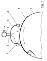
- Figure 1 shows an impression cylinder 1, on the metallic conductive surface by indicated gripper devices held sheet 2 rests.
- the impression cylinder 1 of the printing unit not shown is a chamber extending across the format width of the cylinder 3 assigned.
- the inside of the chamber 3, which is the surface of the arc 2 is assigned, via a feed line 5 with a suction device 4 connected.
- the inside of the Chamber 3 air can thus via the supply line 5 and the suction device 4 are suctioned off.
- Fig. 2 shows the wiring of the two high voltage electrodes 6, 7. These are connected to a high voltage source 8, the impression cylinder 1 or generally the electrically conductive pad of the sheet 2 as a counter electrode (Ground) also connected to the high voltage source 8 is.
- the high voltage source 8 are not signals machine control shown can be fed so that the value for the high voltage application of the printing speed and in particular also the operating mode of the printing press can be selected accordingly.
Landscapes
- Engineering & Computer Science (AREA)
- Mechanical Engineering (AREA)
- Drying Of Solid Materials (AREA)
- Supply, Installation And Extraction Of Printed Sheets Or Plates (AREA)
- Printing Methods (AREA)
Abstract
Description
- Fig. 1
- eine Trocknereinrichtung nach der Erfindung an einen Gegendruckzylinder, und
- Fig. 2
- die Komponenten zur Spannungsbeaufschlagung der Elektroden.
- 1
- Zylinder (Gegendruckzylinder)
- 2
- Bogen
- 3
- Kammer (Absaugkammer-Trockner)
- 4
- Absaugeinrichtung
- 5
- Zuführung / Verbindung
- 6
- Hochspannungselektrode
- 7
- Hochspannungselektrode
- 8
- Hochspannungsquelle
Claims (9)
- Trocknereinrichtung für eine Bogendruckmaschine, insbesondere Bogenoffsetdruckmaschine, mit einer Absaugeinrichtung für oberhalb eines Bogens befindliches Gas,
dadurch gekennzeichnet, dass bezogen auf die Bewegungsrichtung des Bogens (2) der Absaugeinrichtung (4) je eine mit einer elektrisch leitfähigen Unterlage des Bogens (2) (Zylinder 1) zusammenwirkende Hochspannungselektrode (6) vor- und nachgeordnet ist. - Trocknereinrichtung nach Anspruch 1,
dadurch gekennzeichnet, dass die Absaugeinrichtung (4) einer zum Bogen (2) offenen Kammer (3) zugeordnet ist, welche an der jeweils vor- und nachlaufenden Kante eine Hochspannungselektrode (6, 7) aufweist. - Trocknereinrichtung nach Anspruch 1 oder 2,
dadurch gekennzeichnet, dass die Hochspannungselektroden (6, 7) beweglich gegenüber der Oberfläche des Bogens (2) angeordnet sind. - Trocknereinrichtung nach Anspruch 3,
dadurch gekennzeichnet, dass die Hochspannungselektroden (6, 7) nebst der dazwischen befindlichen Absaugeinrichtung (4) beweglich gegenüber der Oberfläche des Bogens (2) angeordnet sind. - Trocknereinrichtung nach einem der Ansprüche 3 oder 4,
dadurch gekennzeichnet, dass die Bewegung der Hochspannungselektroden (6, 7) in Abhängigkeit der Bewegung des Bogens (2) erfolgt. - Trocknereinrichtung nach einem der Ansprüche 3 bis 5,
dadurch gekennzeichnet, dass die Hochspannungselektroden (6, 7) Ausweicheinrichtungen gegenüber den Bogen (2) haltender Greifereinrichtungen ausführen. - Trocknereinrichtung nach einem der vorhergehenden Ansprüche,
dadurch gekennzeichnet, dass die Hochspannungselektroden (6, 7) einem den Bogen (2) tragenden Zylinder (1) zugeordnet sind. - Trocknereinrichtung nach einem der vorhergehenden Ansprüche,
dadurch gekennzeichnet, dass die Hochspannungselektroden (6, 7) einer den Bogen (2) tragenden metallisch leitfähigen Bogenführungsbahn zugeordnet sind. - Trocknereinrichtung nach einem der vorhergehenden Ansprüche,
dadurch gekennzeichnet, dass die Elektroden (6, 7) und/oder die Gegenelektroden im Auslegersystem gegenüber dem Bewegungsweg der die Bogen (2) haltenden Greifereinrichtungen gesteuert bewegbar aufgehängt sind.
Applications Claiming Priority (2)
| Application Number | Priority Date | Filing Date | Title |
|---|---|---|---|
| DE20101511U DE20101511U1 (de) | 2001-01-30 | 2001-01-30 | Trocknereinrichtung für eine Druckmaschine |
| DE20101511U | 2001-01-30 |
Publications (2)
| Publication Number | Publication Date |
|---|---|
| EP1226941A1 true EP1226941A1 (de) | 2002-07-31 |
| EP1226941B1 EP1226941B1 (de) | 2006-05-31 |
Family
ID=7952214
Family Applications (1)
| Application Number | Title | Priority Date | Filing Date |
|---|---|---|---|
| EP02000909A Expired - Lifetime EP1226941B1 (de) | 2001-01-30 | 2002-01-16 | Trocknereinrichtung mit Hochspannungselektroden für eine Druckmaschine |
Country Status (3)
| Country | Link |
|---|---|
| EP (1) | EP1226941B1 (de) |
| AT (1) | ATE327890T1 (de) |
| DE (2) | DE20101511U1 (de) |
Cited By (1)
| Publication number | Priority date | Publication date | Assignee | Title |
|---|---|---|---|---|
| DE102007052573A1 (de) * | 2007-11-03 | 2009-05-14 | Manroland Ag | Feuchtwerk |
Families Citing this family (1)
| Publication number | Priority date | Publication date | Assignee | Title |
|---|---|---|---|---|
| DE102008001103A1 (de) * | 2008-04-10 | 2009-10-15 | Manroland Ag | Umströmtes Bauteil |
Citations (7)
| Publication number | Priority date | Publication date | Assignee | Title |
|---|---|---|---|---|
| GB1237584A (en) * | 1968-09-10 | 1971-06-30 | Sericol Group Ltd | Drying of wet or damp sheets |
| DE2547902A1 (de) * | 1975-10-25 | 1977-05-05 | Frankenthal Ag Albert | Trocknungskasten fuer bedruckte bogen |
| DE2818832A1 (de) * | 1977-06-02 | 1978-12-07 | Polygraph Leipzig | Trockner fuer bedruckte oder beschichtete bahnen fuer druckmaschinen o.dgl. |
| DE2830870A1 (de) * | 1978-07-13 | 1980-01-31 | Screen Printing Supplies | Verfahren und vorrichtung zum trocknen von fotoentwicklungstinten |
| DE19525453A1 (de) | 1995-07-13 | 1997-01-16 | Eltex Elektrostatik Gmbh | Vorrichtung zum Ablösen der gasförmigen laminaren Grenzschicht |
| DE29707190U1 (de) * | 1997-04-22 | 1997-09-25 | Sächsisches Institut für die Druckindustrie GmbH, 04439 Engelsdorf | Einrichtung zur Inertisierung an Druckmaschinen |
| DE19857984A1 (de) * | 1998-12-16 | 2000-06-21 | Koenig & Bauer Ag | Mit Excimer-Strahlern arbeitender Trockner in Bogendruckmaschinen |
-
2001
- 2001-01-30 DE DE20101511U patent/DE20101511U1/de not_active Expired - Lifetime
-
2002
- 2002-01-16 EP EP02000909A patent/EP1226941B1/de not_active Expired - Lifetime
- 2002-01-16 DE DE50206945T patent/DE50206945D1/de not_active Expired - Lifetime
- 2002-01-16 AT AT02000909T patent/ATE327890T1/de active
Patent Citations (7)
| Publication number | Priority date | Publication date | Assignee | Title |
|---|---|---|---|---|
| GB1237584A (en) * | 1968-09-10 | 1971-06-30 | Sericol Group Ltd | Drying of wet or damp sheets |
| DE2547902A1 (de) * | 1975-10-25 | 1977-05-05 | Frankenthal Ag Albert | Trocknungskasten fuer bedruckte bogen |
| DE2818832A1 (de) * | 1977-06-02 | 1978-12-07 | Polygraph Leipzig | Trockner fuer bedruckte oder beschichtete bahnen fuer druckmaschinen o.dgl. |
| DE2830870A1 (de) * | 1978-07-13 | 1980-01-31 | Screen Printing Supplies | Verfahren und vorrichtung zum trocknen von fotoentwicklungstinten |
| DE19525453A1 (de) | 1995-07-13 | 1997-01-16 | Eltex Elektrostatik Gmbh | Vorrichtung zum Ablösen der gasförmigen laminaren Grenzschicht |
| DE29707190U1 (de) * | 1997-04-22 | 1997-09-25 | Sächsisches Institut für die Druckindustrie GmbH, 04439 Engelsdorf | Einrichtung zur Inertisierung an Druckmaschinen |
| DE19857984A1 (de) * | 1998-12-16 | 2000-06-21 | Koenig & Bauer Ag | Mit Excimer-Strahlern arbeitender Trockner in Bogendruckmaschinen |
Cited By (2)
| Publication number | Priority date | Publication date | Assignee | Title |
|---|---|---|---|---|
| DE102007052573A1 (de) * | 2007-11-03 | 2009-05-14 | Manroland Ag | Feuchtwerk |
| DE102007052573B4 (de) * | 2007-11-03 | 2015-04-09 | Manroland Web Systems Gmbh | Feuchtwerk |
Also Published As
| Publication number | Publication date |
|---|---|
| ATE327890T1 (de) | 2006-06-15 |
| EP1226941B1 (de) | 2006-05-31 |
| DE20101511U1 (de) | 2001-03-29 |
| DE50206945D1 (de) | 2006-07-06 |
Similar Documents
| Publication | Publication Date | Title |
|---|---|---|
| EP4209351B1 (de) | Bogenverarbeitende maschine, verwendung der bogenverarbeitenden maschine, verfahren zum fördern von bogen und verwendung von entionisationseinrichtungen enthaltenden bogenleitelementen | |
| EP1303407B1 (de) | Trocknereinrichtung innerhalb einer bogendruckmaschine | |
| DE19857984B4 (de) | Mit Excimer-Strahlern arbeitender Trockner in Bogendruckmaschinen | |
| EP2574463A1 (de) | Bogendruckmaschine | |
| DE102016200544B4 (de) | Vorrichtung zur Behandlung von bogenförmigem Substrat | |
| DE19753089C2 (de) | Bogenführungseinrichtung in einer Druckmaschine | |
| DE102019118565A1 (de) | Bogenverarbeitende Maschine und Verfahren zum Fördern von Bogen | |
| EP0922577B1 (de) | Bogenführungseinrichtung in einer Druckmaschine | |
| DE19829095A1 (de) | Bogenführungseinrichtung in einer Druckmaschine | |
| EP1120250B1 (de) | Transportsystem für eine Druckmaschine | |
| EP1226941B1 (de) | Trocknereinrichtung mit Hochspannungselektroden für eine Druckmaschine | |
| DE10157566B4 (de) | Bogenleiteinrichtung mit einer Führungsfläche in einer Druckmaschine | |
| DE102011005824A1 (de) | Verarbeitungsmaschine mit einem Ausleger für Bogenmaterial | |
| DE10056018A1 (de) | Einrichtung zur Unterstützung der Bogenführung und Bogenablage | |
| EP1285755A1 (de) | Beschichtungsmaschine zum Veredeln von Druckbogen | |
| DE10302367A1 (de) | Vorrichtung zum Ersetzen des Luftsauerstoffs durch ein Inertgas aus einer laminaren Luftgrenzschicht sowie Verwendung derselben | |
| DE4342203C2 (de) | Einrichtung zum Einwirken auf Bogen in einer Bogenrotationsdruckmaschine | |
| EP1199165B1 (de) | Einrichtung zum Einwirken auf Bedruckstoffe innerhalb einer Druckmaschine | |
| DE102013226315A1 (de) | Bogenverarbeitende Maschine mit einem Bearbeitungswerk und einer Auslage und Verfahren zum Betreiben einer bogenverarbeitenden Maschine | |
| EP2524807A1 (de) | Verfahren zum Auslegen von Bogenmaterial in einer Bogenverarbeitungsmaschine und Auslegervorrichtung | |
| DE9310028U1 (de) | Bedruckstoffkühlung in Auslegern von Bogenrotationsdruckmaschinen | |
| DE102019118569B4 (de) | Bogenverarbeitende Maschine und Verfahren zum Fördern von Bogen | |
| DE10158050A1 (de) | Verfahren und Vorrichtung zum Abkühlen eines Bedruckstoffes in einer Rotationsdruckmaschine | |
| DE102016200546B4 (de) | Vorrichtung zur Behandlung von bogenförmigem Substrat | |
| DE102019118566A1 (de) | Bogenverarbeitende Maschine und Verfahren zum Fördern von Bogen |
Legal Events
| Date | Code | Title | Description |
|---|---|---|---|
| PUAI | Public reference made under article 153(3) epc to a published international application that has entered the european phase |
Free format text: ORIGINAL CODE: 0009012 |
|
| AK | Designated contracting states |
Kind code of ref document: A1 Designated state(s): AT BE CH CY DE DK ES FI FR GB GR IE IT LI LU MC NL PT SE TR |
|
| AX | Request for extension of the european patent |
Free format text: AL;LT;LV;MK;RO;SI |
|
| 17P | Request for examination filed |
Effective date: 20020606 |
|
| AKX | Designation fees paid |
Designated state(s): AT BE CH CY DE DK ES FI FR GB GR IE IT LI LU MC NL PT SE TR |
|
| 17Q | First examination report despatched |
Effective date: 20041222 |
|
| GRAP | Despatch of communication of intention to grant a patent |
Free format text: ORIGINAL CODE: EPIDOSNIGR1 |
|
| GRAS | Grant fee paid |
Free format text: ORIGINAL CODE: EPIDOSNIGR3 |
|
| GRAA | (expected) grant |
Free format text: ORIGINAL CODE: 0009210 |
|
| AK | Designated contracting states |
Kind code of ref document: B1 Designated state(s): AT BE CH CY DE DK ES FI FR GB GR IE IT LI LU MC NL PT SE TR |
|
| PG25 | Lapsed in a contracting state [announced via postgrant information from national office to epo] |
Ref country code: FI Free format text: LAPSE BECAUSE OF FAILURE TO SUBMIT A TRANSLATION OF THE DESCRIPTION OR TO PAY THE FEE WITHIN THE PRESCRIBED TIME-LIMIT Effective date: 20060531 Ref country code: IT Free format text: LAPSE BECAUSE OF FAILURE TO SUBMIT A TRANSLATION OF THE DESCRIPTION OR TO PAY THE FEE WITHIN THE PRESCRIBED TIME-LIMIT;WARNING: LAPSES OF ITALIAN PATENTS WITH EFFECTIVE DATE BEFORE 2007 MAY HAVE OCCURRED AT ANY TIME BEFORE 2007. THE CORRECT EFFECTIVE DATE MAY BE DIFFERENT FROM THE ONE RECORDED. Effective date: 20060531 Ref country code: GB Free format text: LAPSE BECAUSE OF FAILURE TO SUBMIT A TRANSLATION OF THE DESCRIPTION OR TO PAY THE FEE WITHIN THE PRESCRIBED TIME-LIMIT Effective date: 20060531 Ref country code: NL Free format text: LAPSE BECAUSE OF FAILURE TO SUBMIT A TRANSLATION OF THE DESCRIPTION OR TO PAY THE FEE WITHIN THE PRESCRIBED TIME-LIMIT Effective date: 20060531 Ref country code: IE Free format text: LAPSE BECAUSE OF FAILURE TO SUBMIT A TRANSLATION OF THE DESCRIPTION OR TO PAY THE FEE WITHIN THE PRESCRIBED TIME-LIMIT Effective date: 20060531 |
|
| REG | Reference to a national code |
Ref country code: CH Ref legal event code: EP Ref country code: GB Ref legal event code: FG4D Free format text: NOT ENGLISH |
|
| REG | Reference to a national code |
Ref country code: IE Ref legal event code: FG4D Free format text: LANGUAGE OF EP DOCUMENT: GERMAN |
|
| REF | Corresponds to: |
Ref document number: 50206945 Country of ref document: DE Date of ref document: 20060706 Kind code of ref document: P |
|
| PG25 | Lapsed in a contracting state [announced via postgrant information from national office to epo] |
Ref country code: DK Free format text: LAPSE BECAUSE OF FAILURE TO SUBMIT A TRANSLATION OF THE DESCRIPTION OR TO PAY THE FEE WITHIN THE PRESCRIBED TIME-LIMIT Effective date: 20060831 Ref country code: SE Free format text: LAPSE BECAUSE OF FAILURE TO SUBMIT A TRANSLATION OF THE DESCRIPTION OR TO PAY THE FEE WITHIN THE PRESCRIBED TIME-LIMIT Effective date: 20060831 |
|
| PG25 | Lapsed in a contracting state [announced via postgrant information from national office to epo] |
Ref country code: ES Free format text: LAPSE BECAUSE OF FAILURE TO SUBMIT A TRANSLATION OF THE DESCRIPTION OR TO PAY THE FEE WITHIN THE PRESCRIBED TIME-LIMIT Effective date: 20060911 |
|
| PG25 | Lapsed in a contracting state [announced via postgrant information from national office to epo] |
Ref country code: PT Free format text: LAPSE BECAUSE OF FAILURE TO SUBMIT A TRANSLATION OF THE DESCRIPTION OR TO PAY THE FEE WITHIN THE PRESCRIBED TIME-LIMIT Effective date: 20061031 |
|
| NLV1 | Nl: lapsed or annulled due to failure to fulfill the requirements of art. 29p and 29m of the patents act | ||
| GBV | Gb: ep patent (uk) treated as always having been void in accordance with gb section 77(7)/1977 [no translation filed] |
Effective date: 20060531 |
|
| PG25 | Lapsed in a contracting state [announced via postgrant information from national office to epo] |
Ref country code: CH Free format text: LAPSE BECAUSE OF NON-PAYMENT OF DUE FEES Effective date: 20070131 Ref country code: LI Free format text: LAPSE BECAUSE OF NON-PAYMENT OF DUE FEES Effective date: 20070131 Ref country code: MC Free format text: LAPSE BECAUSE OF NON-PAYMENT OF DUE FEES Effective date: 20070131 |
|
| REG | Reference to a national code |
Ref country code: IE Ref legal event code: FD4D |
|
| PLBE | No opposition filed within time limit |
Free format text: ORIGINAL CODE: 0009261 |
|
| STAA | Information on the status of an ep patent application or granted ep patent |
Free format text: STATUS: NO OPPOSITION FILED WITHIN TIME LIMIT |
|
| EN | Fr: translation not filed | ||
| 26N | No opposition filed |
Effective date: 20070301 |
|
| REG | Reference to a national code |
Ref country code: CH Ref legal event code: PL |
|
| BERE | Be: lapsed |
Owner name: MAN ROLAND DRUCKMASCHINEN A.G. Effective date: 20070131 |
|
| PG25 | Lapsed in a contracting state [announced via postgrant information from national office to epo] |
Ref country code: BE Free format text: LAPSE BECAUSE OF NON-PAYMENT OF DUE FEES Effective date: 20070131 |
|
| PG25 | Lapsed in a contracting state [announced via postgrant information from national office to epo] |
Ref country code: GR Free format text: LAPSE BECAUSE OF FAILURE TO SUBMIT A TRANSLATION OF THE DESCRIPTION OR TO PAY THE FEE WITHIN THE PRESCRIBED TIME-LIMIT Effective date: 20060901 Ref country code: FR Free format text: LAPSE BECAUSE OF FAILURE TO SUBMIT A TRANSLATION OF THE DESCRIPTION OR TO PAY THE FEE WITHIN THE PRESCRIBED TIME-LIMIT Effective date: 20070309 |
|
| PG25 | Lapsed in a contracting state [announced via postgrant information from national office to epo] |
Ref country code: FR Free format text: LAPSE BECAUSE OF FAILURE TO SUBMIT A TRANSLATION OF THE DESCRIPTION OR TO PAY THE FEE WITHIN THE PRESCRIBED TIME-LIMIT Effective date: 20060531 |
|
| PG25 | Lapsed in a contracting state [announced via postgrant information from national office to epo] |
Ref country code: LU Free format text: LAPSE BECAUSE OF NON-PAYMENT OF DUE FEES Effective date: 20070116 Ref country code: CY Free format text: LAPSE BECAUSE OF FAILURE TO SUBMIT A TRANSLATION OF THE DESCRIPTION OR TO PAY THE FEE WITHIN THE PRESCRIBED TIME-LIMIT Effective date: 20060531 |
|
| PG25 | Lapsed in a contracting state [announced via postgrant information from national office to epo] |
Ref country code: TR Free format text: LAPSE BECAUSE OF FAILURE TO SUBMIT A TRANSLATION OF THE DESCRIPTION OR TO PAY THE FEE WITHIN THE PRESCRIBED TIME-LIMIT Effective date: 20060531 |
|
| PGFP | Annual fee paid to national office [announced via postgrant information from national office to epo] |
Ref country code: DE Payment date: 20120210 Year of fee payment: 11 |
|
| REG | Reference to a national code |
Ref country code: DE Ref legal event code: R081 Ref document number: 50206945 Country of ref document: DE Owner name: MANROLAND SHEETFED GMBH, DE Free format text: FORMER OWNER: MANROLAND AG, 63075 OFFENBACH, DE Effective date: 20120509 |
|
| PGFP | Annual fee paid to national office [announced via postgrant information from national office to epo] |
Ref country code: AT Payment date: 20120120 Year of fee payment: 11 |
|
| REG | Reference to a national code |
Ref country code: AT Ref legal event code: MM01 Ref document number: 327890 Country of ref document: AT Kind code of ref document: T Effective date: 20130131 |
|
| PG25 | Lapsed in a contracting state [announced via postgrant information from national office to epo] |
Ref country code: DE Free format text: LAPSE BECAUSE OF NON-PAYMENT OF DUE FEES Effective date: 20130801 Ref country code: AT Free format text: LAPSE BECAUSE OF NON-PAYMENT OF DUE FEES Effective date: 20130131 |
|
| REG | Reference to a national code |
Ref country code: DE Ref legal event code: R119 Ref document number: 50206945 Country of ref document: DE Effective date: 20130801 |