EP1225303A2 - Blade structure in a gas turbine - Google Patents
Blade structure in a gas turbine Download PDFInfo
- Publication number
- EP1225303A2 EP1225303A2 EP01130467A EP01130467A EP1225303A2 EP 1225303 A2 EP1225303 A2 EP 1225303A2 EP 01130467 A EP01130467 A EP 01130467A EP 01130467 A EP01130467 A EP 01130467A EP 1225303 A2 EP1225303 A2 EP 1225303A2
- Authority
- EP
- European Patent Office
- Prior art keywords
- blade
- chip
- stationary
- moving
- angle
- Prior art date
- Legal status (The legal status is an assumption and is not a legal conclusion. Google has not performed a legal analysis and makes no representation as to the accuracy of the status listed.)
- Withdrawn
Links
Images







Classifications
-
- F—MECHANICAL ENGINEERING; LIGHTING; HEATING; WEAPONS; BLASTING
- F01—MACHINES OR ENGINES IN GENERAL; ENGINE PLANTS IN GENERAL; STEAM ENGINES
- F01D—NON-POSITIVE DISPLACEMENT MACHINES OR ENGINES, e.g. STEAM TURBINES
- F01D5/00—Blades; Blade-carrying members; Heating, heat-insulating, cooling or antivibration means on the blades or the members
- F01D5/12—Blades
- F01D5/14—Form or construction
- F01D5/141—Shape, i.e. outer, aerodynamic form
- F01D5/142—Shape, i.e. outer, aerodynamic form of the blades of successive rotor or stator blade-rows
-
- F—MECHANICAL ENGINEERING; LIGHTING; HEATING; WEAPONS; BLASTING
- F01—MACHINES OR ENGINES IN GENERAL; ENGINE PLANTS IN GENERAL; STEAM ENGINES
- F01D—NON-POSITIVE DISPLACEMENT MACHINES OR ENGINES, e.g. STEAM TURBINES
- F01D5/00—Blades; Blade-carrying members; Heating, heat-insulating, cooling or antivibration means on the blades or the members
- F01D5/12—Blades
- F01D5/14—Form or construction
- F01D5/141—Shape, i.e. outer, aerodynamic form
-
- F—MECHANICAL ENGINEERING; LIGHTING; HEATING; WEAPONS; BLASTING
- F01—MACHINES OR ENGINES IN GENERAL; ENGINE PLANTS IN GENERAL; STEAM ENGINES
- F01D—NON-POSITIVE DISPLACEMENT MACHINES OR ENGINES, e.g. STEAM TURBINES
- F01D5/00—Blades; Blade-carrying members; Heating, heat-insulating, cooling or antivibration means on the blades or the members
- F01D5/12—Blades
- F01D5/14—Form or construction
- F01D5/141—Shape, i.e. outer, aerodynamic form
- F01D5/145—Means for influencing boundary layers or secondary circulations
-
- F—MECHANICAL ENGINEERING; LIGHTING; HEATING; WEAPONS; BLASTING
- F05—INDEXING SCHEMES RELATING TO ENGINES OR PUMPS IN VARIOUS SUBCLASSES OF CLASSES F01-F04
- F05D—INDEXING SCHEME FOR ASPECTS RELATING TO NON-POSITIVE-DISPLACEMENT MACHINES OR ENGINES, GAS-TURBINES OR JET-PROPULSION PLANTS
- F05D2240/00—Components
- F05D2240/10—Stators
- F05D2240/12—Fluid guiding means, e.g. vanes
Definitions
- This invention relates to a blade structure in a gas turbine. More particularly, this invention relates to a blade structure of a gas turbine with improved turbine efficiency by restricting pressure loss to a minimum level.
- a gas turbine will be explained with reference to Fig. 16.
- a gas turbine is equipped with a plurality of stages of stationary blades 2 and 3 arrayed in a circle on a casing (a blade circle or a vehicle chamber) 1, and a plurality of moving blades 5 arrayed in a circle on a rotor (a hub of a base) 4.
- Fig. 16 shows the moving blade 5 at a certain stage, the stationary blade 2 at the same stage (the inlet side of combustion gas 6) as this moving blade 5, and the stationary blade 3 at the next stage (the outlet side of the combustion gas 6) of this moving blade 5.
- a main flow (shown by a solid-line arrow mark in Fig. 17) of combustion gas 6 flows to the next-stage stationary blade 3 side by passing through between the moving blade 5 and the moving blade 5.
- a leakage flow 9 shown by a broken-line arrow mark in Fig. 17
- a mechanism of generating the leakage flow 9 is that as the pressure at a belly surface 10 side of the moving blade 5 is higher than the pressure at a rear surface 11 side of the moving blade 5, the leakage flow 9 is generated from the belly surface 10 side to the rear surface 11 side based on a difference between these pressures.
- the leakage flow 9 flows at an incidence angle ic to the rear surface 13 side at a front edge 12 of the chip of the stationary blade 3 at the next stage.
- This leakage flow 9 becomes a flow opposite to the main flow of the combustion gas 6 that flows to the belly surface 14 side of the stationary blade 3.
- a vortex flow 15 (shown by a solid-line spiral arrow mark in Fig. 17) is generated at the belly surface 14 side of the front edge 12 of the chip of the stationary blade 3.
- pressure loss occurs.
- the main flow of the combustion gas 6 may deviate from the belly surface 14 side of the stationary blade 3.
- a reference symbol ⁇ c denotes an entrance metal angle at the chip portion of the stationary blade 3.
- a reference symbol ⁇ c denotes a front-edge including angle at the chip portion of the stationary blade 3.
- a reference number 22 denotes a camber line for connecting between the front edge 12 of the chip portion of the stationary blade 3 and a rear edge 23 of the chip portion.
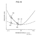
- the incidence angle ic of the leakage flow 9 and the pressure loss have a relative relationship as shown by a solid-line curve in Fig. 18.
- the solid-line curve in Fig. 18 shows a case of the front-edge including angle ⁇ c at the chip portion of the stationary blade 3 shown in Fig. 17.
- the front-edge including angle ⁇ c at the chip portion of the stationary blade 3 has been set such that the pressure loss becomes minimum (refer to a point P1 in Fig. 18).
- the leakage flow 9 is generated, and the pressure loss also becomes large when the incidence angle ic of this leakage flow 9 is large (refer to a point P2 in Fig. 18).
- this pressure loss is large, the turbine efficiency is lowered by that amount.
- seal-air 16 (shown by a two-dot chained line arrow mark in Fig. 16) flows from the rotor 4 side at the upstream of the moving blade 5 at a certain stage.
- this seal-air 16 is flowing, there is the following problem.
- the seal-air 16 simply flows out straight in a direction of the height (a radial direction of the turbine) of the moving blade 5 without being squeezed by a nozzle or the like.
- the movingblade 5 is rotating in a direction of an outline arrow mark together with the rotor 4. Therefore, from the relative relationship between the flow-out of the seal-air 16 and the rotation of the moving blade 5, the seal-air 16 flows at the incidence angle is to the rear-surface side 11 at the front edge 17 of the hub portion of the moving blade 5, as shown in Fig. 17.
- a reference symbol ⁇ s denotes an entrance metal angle at the hub portion of the moving blade 5.
- a reference symbol ⁇ s denotes a front-edge including angle at the hub portion of the moving blade 5.
- a reference number 24 denotes a camber line for connecting between the front edge 17 of the hub portion of the moving blade 5 and a rear edge 25 of the hub portion.
- the leakage flow 9 is generated from the belly surface 10 side of the moving blade 5 to the rear surface 11 side, at the clearance 8 between the chip 7 of the free-standing moving blade 5 and the casing 1.
- a design Mach number distribution shown by a solid-line curve becomes an actual Mach number distribution as shown by a broken-line curve.
- deceleration from an intermediate portion to a rear edge 19 is larger in actual Mach distribution G2 than in design Mach distribution G1.
- a boundary layer (a portion provided with shaded lines) 20 at a portion from the intermediate portion to the rear edge 19 swells on the rear surface 11 of the chip portion 18 of the moving blade 5.
- a reference number 21 in Fig. 19 denotes a front edge of the chip portion 18 of the moving blade 5.
- a front-edge including angle at a chip portion of the stationary blade that is the stationary blade at the rear stage of the moving blade having the chip clearance is larger than a front-edge including angle at other portions than the chip portion of the stationary blade.
- a curve of a relative relationship between the incidence angle and the pressure loss becomes mild by making the front-edge including angle large. It is possible to reduce the pressure loss by that amount, and therefore, it becomes possible to improve the turbine efficiency.
- an entrance metal angle at a chip portion of the stationary blade that is the stationary blade at the rear stage of the moving blade having the chip clearance is made smaller than an entrance metal angle at other portions than the chip portion of the stationary blade.
- a front-edge including angle at a chip portion of the stationary blade that is the stationary blade at the rear stage of the moving blade having the chip clearance is made larger than a front-edge including angle at other portions than the chip portion of the stationary blade, and also an entrance metal angle at a chip portion of the stationary blade is made smaller than an entrance metal angle at other portions than the chip portion of the stationary blade.
- a curve of a relative relationship between the incidence angle and the pressure loss becomes mild by making the front-edge including angle large. It is possible to reduce the pressure loss by that amount, and therefore, it becomes possible to improve the turbine efficiency. Moreover, it is possible to make the incidence angle small by making the entrance metal angle small. Also, it is possible to reduce the pressure loss by that amount, and therefore, it becomes possible to improve the turbine efficiency. Moreover, it is possible to make the pressure loss much smaller based on a synergy effect of the work that a curve of a relative relationship between the incidence angle and the pressure loss becomes mild and the work that the incidence angle can be made small.
- a front-edge including angle at a hub portion of the stationary blade is made larger than a front-edge including angle at other portions than the hub portion of the moving blade.
- a curve of a relative relationship between the incidence angle and the pressure loss becomes mild by making the front-edge including angle large. It is possible to reduce the pressure loss by that amount, and therefore, it becomes possible to improve the turbine efficiency.
- an entrance metal angle at a hub portion of the stationary blade is made smaller than an entrance metal angle at other portions than the hub portion of the moving blade.
- a front-edge including angle at a hub portion of the stationary blade is made larger than a front-edge including angle at other portions than the hub portion of the moving blade, and also an entrance metal angle at a hub portion of the stationary blade is made smaller than an entrance metal angle at other portions than the hub portion of the moving blade.
- a curve of a relative relationship between the incidence angle and the pressure loss becomes mild by making the front-edge including angle large. It is possible to reduce the pressure loss by that amount, and therefore, it becomes possible to improve the turbine efficiency. Moreover, it is possible to make the incidence angle small by making the entrance metal angle small. It is possible to reduce the pressure loss by that amount, and therefore, it becomes possible to improve the turbine efficiency. Furthermore, it is possible to make the pressure loss much smaller based on a synergy effect of the work that a curve of a relative relationship between the incidence angle and the pressure loss becomes mild and the work that the incidence angle can be made small.
- a chord length at a chip portion of the moving blade having the chip clearance is made larger than a minimum chord length at other portions than the chip portion of the moving blade.
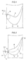
- Fig. 1 is an explanatory diagram showing a first embodiment of a blade structure in a gas turbine relating to this invention.
- reference numbers that are the same as those in Fig. 16 to Fig. 19 show the identical portions.
- a blade structure in a first embodiment relates to a stationary blade 3 at the rear stage of a moving blade having a chip clearance.
- a front-edge including angle ⁇ c1 at a front edge of a chip portion (a cross section of a chip) of the stationary blade 3 is made larger than a front-edge including angle of portions (a cross section of a hub portion to a mean portion) other than the chip portion of this stationary blade 3. For example, this is made larger than about 5°.
- the front-edge including angle ⁇ c1 is taken large at the chip portion of the stationary blade 3 at the rear stage of the moving blade having the chip clearance.
- Fig. 2 is an explanatory diagram showing a second embodiment of a blade structure in a gas turbine relating to this invention.
- reference numbers that are the same as those in Fig. 1 and Fig. 16 to Fig. 19 show the identical portions.
- a blade structure in a second embodiment relates to a stationary blade 3 at the rear stage of a moving blade having a chip clearance.
- An entrance metal angle ⁇ c1 of a chip portion (a cross section of a chip) of this stationary blade 3 is made smaller than an entrance metal angle of portions (a cross section of a hub portion to a mean portion) other than the chip portion of this stationary blade 3.
- the entrance metal angle ⁇ c1 of the cross section of the chip portion of the stationary blade 3 is directed toward a rear surface 13 side by about 10°, for example, as compared with the entrance metal angle of the cross section of the hub portion to the mean portion.
- the entrance metal angle ⁇ c1 is taken small at the chip portion of the stationary blade 3 at the rear stage of the moving blade having the chip clearance.
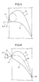
- FIG. 3 and Fig. 4 are explanatory diagrams showing a third embodiment of a blade structure in a gas turbine relating to this invention.
- reference numbers that are the same as those in Fig. 1, Fig. 2 and Fig. 16 to Fig. 19 show the identical portions.
- a blade structure in a third embodiment relates to a stationary blade 3 at the rear stage of a moving blade having a chip clearance.
- a front-edge including angle ⁇ c1 at a front edge of a chip portion (a cross section of a chip) of the stationary blade 3 is made larger than a front-edge including angle of portions (a cross section of a hub portion to a mean portion) other than the chip portion of this stationary blade 3. For example, this is made larger than about 5°.
- an entrance metal angle ⁇ c1 of a chip portion (a cross section of a chip) of this stationary blade 3 is made smaller than an entrance metal angle of portions (a cross section of a hub portion to a mean portion) other than the chip portion of this stationary blade 3.
- the entrance metal angle ⁇ c1 of the cross section of the chip portion of the stationary blade 3 is directed toward a rear surface 13 side by about 10°, for example, as compared with the entrance metal angle of the cross section of the hub portion to the mean portion.
- the front-edge including angle ⁇ c1 is taken large at the chip portion of the stationary blade 3 at the rear stage of the moving blade having the chip clearance.
- the entrance metal angle ⁇ c1 is taken small at the chip portion of the stationary blade 3 at the rear stage of the moving blade having the chip clearance.
- the blade structure of this third embodiment it is possible to make the pressure loss much smaller, based on a synergy effect of the work that a curve of a relative relationship between the incidence angle and the pressure loss becomes mild as shown by the broken-line curve in Fig. 18 and the work that the incidence angle ic1 can be made small as shown by a point P5 in Fig. 18. As a result, it becomes possible to improve the turbine efficiency.
- Fig. 5 is an explanatory diagram showing a first embodiment of a blade structure in a gas turbine relating to this invention.
- reference numbers that are the same as those in Fig. 1 to Fig. 4 and Fig. 16 to Fig. 19 show the identical portions.
- a blade structure in a fourth embodiment relates to a moving blade 5 like a free-standing moving blade and a shrouded moving blade.
- a front-edge including angle ⁇ s1 at a hub portion (a cross section of a hub portion) of this moving blade 5 is made larger than a front-edge including angle of portions (a cross section of a chip portion to a mean portion) other than the hub portion of this moving blade 5. For example, this is made larger than about 5°.
- the front-edge including angle ⁇ s1 is taken large at the hub portion of this moving blade 5.
- a curve of a relative relationship between the incidence angle and the pressure loss becomes mild as shown by the broken-line curve in Fig. 18.
- Fig. 6 is an explanatory diagram showing a fifth embodiment of a blade structure in a gas turbine relating to this invention.
- reference numbers that are the same as those in Fig. 1 to Fig. 5 and Fig. 16 to Fig. 19 show the identical portions.
- a blade structure in a fifth embodiment relates to a moving blade 5 like a free-standing moving blade and a shrouded moving blade.
- An entrance metal angle ⁇ s1 of a hub portion (a cross section of a hub portion) of this moving blade 5 is made smaller than an entrance metal angle of portions (a cross section of a chip portion to a mean portion) other than the hub portion of this moving blade 5.
- the entrance metal angle ⁇ s1 of the cross section of the hub portion of the moving blade 5 is directed toward a rear surface 11 side by about 10°, for example, as compared with the entrance metal angle of the cross section of the chip portion to the mean portion.
- the entrance metal angle ⁇ s1 is taken small at the hub portion of the moving blade 5.
- Fig. 7 and Fig. 8 are explanatory diagrams showing a sixth embodiment of a blade structure in a gas turbine relating to this invention.
- reference numbers that are the same as those in Fig. 1 to Fig. 6 and Fig. 16 to Fig. 19 show the identical portions.
- a blade structure in a sixth embodiment relates to a moving blade 5 like a free-standing moving blade and a shrouded moving blade.
- a front-edge including angle ⁇ s1 at a hub portion (a cross section of a hub portion) of this moving blade 5 is made larger than a front-edge including angle of portions (a cross section of a chip portion to a mean portion) other than the hub portion of this moving blade 5. For example, this is made larger than about 5°.
- an entrance metal angle ⁇ s1 of a hub portion (a cross section of a hub portion) of this moving blade 5 is made smaller than an entrance metal angle of portions (a cross section of a chip portion to a mean portion) other than the hub portion of this moving blade 5.
- the entrance metal angle ⁇ s1 of the cross section of the hub portion of the moving blade 5 is directed toward a rear surface 11 side by about 10°, for example, as compared with the entrance metal angle of the cross section of the chip portion to the mean portion.
- the front-edge including angle ⁇ s1 is taken large at the hub portion of this moving blade 5.
- a curve of a relative relationship between the incidence angle and the pressure loss becomes mild as shown by the broken-line curve in Fig. 18.
- the entrance metal angle ⁇ s1 is taken small at the hub portion of the moving blade 5.
- the blade structure of this sixth embodiment it is possible to make the pressure loss much smaller, based on a synergy effect of the work that a curve of a relative relationship between the incidence angle and the pressure loss becomes mild as shown by the broken-line curve in Fig. 18 and the work that the incidence angle is1 can be made small as shown by the point P5 in Fig. 18. As a result, it becomes possible to improve the turbine efficiency.
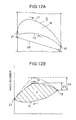
- Fig. 9 and Fig. 12 are explanatory diagrams showing a seventh embodiment of a blade structure in a gas turbine relating to this invention.
- reference numbers that are the same as those in Fig. 1 to Fig. 8 and Fig. 16 to Fig. 19 show the identical portions.
- a blade structure in a seventh embodiment relates to a moving blade 5 like a free-standing moving blade and a shrouded moving blade.
- a chord length 26 at a chip portion 18 (a cross section of the chip portion 18) of this moving blade 5 is made larger than a minimum chord length at other portions (a cross section of a hub portion to a mean section) than the chip portion of the moving blade 5.
- the chord length 26 of the cross section of the chip portion 18 is made equal to or larger than the chord length of the mean cross section (a ratio of pitch to chord is set larger than a conventional ratio).
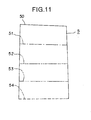
- Fig. 9 is an explanatory diagram of a cross section showing a stacking shape of the moving blade 5.
- a stacking shape shown by a reference number 50 and a solid line show a chip.
- a stacking shape shown by a reference number 51 and a one-dot chained line show a chip at a position of about 75% of the height from a hub.
- a stacking shape shown by a reference number 52 and a two-dot chained line show a mean.
- a stacking shape shown by a reference number 53 and a three-dot chained line show a chip at a position of about 25% of the height from the hub.
- a stacking shape shown by a reference number 54 and a broken line show the hub.
- the blade structure of this sixth embodiment it is possible to make small the deceleration from an intermediate portion to a rear edge 19 on a rear surface 11 of a chip portion 18 of a moving blade 5, as shown by G4 in Fig. 12B, by making large a chord length 26 of the chip portion 18 of the moving blade 5.
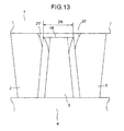
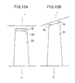
- Fig. 13 to Fig. 15 show modifications of a blade structure in a gas turbine relating to this invention.
- reference numbers that are the same as those in Fig. 1 to Fig. 12 and Fig. 16 to Fig. 19 show the identical portions.
- a modification shown in Fig. 13 is a modification of the seventh embodiment.
- Chip portions of stationary blades 2 and 3 are provided with escape sections 27 for avoiding an interference with a chip portion 18 of a moving blade 5.
- amodification shown in Fig. 14B is amodification of the seventh embodiment.
- the entrance metal angle ⁇ c1 of the chip portion of the stationary blade 3 is made smaller than the entrance metal angle of portions (the hub portion to the mean portion) other than the chip portion of the stationary blade 3.
- the entrance metal angle ⁇ c1 of the chip portion of the stationary blade 3 is directed toward the rear surface 13 side of the stationary blade 3. It is also possible to have a similar structure for the stationary blade 2 at the same stage as that of the moving blade 5.
- the blade structure relating to this invention can also be applied to a cooling moving blade 29 having a hollow portion 28 at the chip portion 18, as shown in Fig. 15A. Further, it is also possible to apply the blade structure relating to this invention to a moving blade 31 of which chip portion 18 has a taper 30 along the taper of the casing 1, as shown in Fig. 15B.
- a front-edge including angle is taken large, at a chip portion of a stationary blade at a rear stage of a moving blade having a chip clearance. Therefore, a curve of a relative relationship between the incidence angle and the pressure loss becomes mild. As it is possible to reduce the pressure loss by that amount, it becomes possible to improve the turbine efficiency.
- the blade structure in a gas turbine relating to another aspect of this invention, it is possible to make an incidence angle small by making an entrance metal angle small, at a chip portion of a stationary blade at a rear stage of a moving blade having a clearance. As it is possible to reduce the pressure loss by that amount, it becomes possible to improve the turbine efficiency.
- a front-edge including angle is taken large at a chip portion of a stationary blade, at a rear stage of a moving blade having a chip clearance. Therefore, a curve of a relative relationship between an incidence angle and a pressure loss becomes mild. As it is possible to reduce the pressure loss by that amount, it becomes possible to improve the turbine efficiency.
- the blade structure in a gas turbine relating to still another aspect of this invention, it is possible to make an incidence angle small by making an entrance metal angle small, at a chip portion of a stationary blade at a rear stage of a moving blade having a clearance. As it is possible to reduce the pressure loss by that amount, it becomes possible to improve the turbine efficiency.
- a curve of a relative relationship between an incidence angle and a pressure loss becomes mild by making a front-edge including angle large at a hub portion of a moving blade. As it is possible to reduce the pressure loss by that amount, it becomes possible to improve the turbine efficiency.
- a curve of a relative relationship between an incidence angle and a pressure loss becomes mild by making a front-edge including angle large at a hub portion of a moving blade. As it is possible to reduce the pressure loss by that amount, it becomes possible to improve the turbine efficiency.
- the blade structure in a gas turbine relating to still another aspect of this invention, it is possible to make small the deceleration from an intermediate portion to a rear edge on a rear surface of a chip portion of a moving blade by making a chord length of the moving blade large. Then, it is possible to minimize the swelling of the boundary layer. As a result, it is possible to make the pressure loss small, and it becomes possible to improve the turbine efficiency by that amount.
- a chip portion of a stationary blade is provided with an escape section for avoiding an interference with a chip portion of a moving blade.
- an entrance metal angle at a chip portion of a stationary blade is smaller than an entrance metal angle at other portions than the chip portion of the stationary blade, it is possible to make an incidence angle small. As it is possible to reduce the pressure loss by that amount, it becomes possible to improve the turbine efficiency.
Landscapes
- Engineering & Computer Science (AREA)
- Physics & Mathematics (AREA)
- Fluid Mechanics (AREA)
- Mechanical Engineering (AREA)
- General Engineering & Computer Science (AREA)
- Turbine Rotor Nozzle Sealing (AREA)
Abstract
Description
Claims (9)
- A blade structure in a gas turbine, comprising:stationary blades arrayed in a circle on a casing;moving blades arrayed in a circle on a rotor, wherein a clearance is provided between chips of the moving blades and the casing, whereina front-edge including angle at a chip portion of the stationary blade that is the stationary blade at the rear stage of the moving blade having the chip clearance is larger than a front-edge including angle at other portions than the chip portion of the stationary blade.
- A blade structure in a gas turbine, comprising:stationary blades arrayed in a circle on a casing;moving blades arrayed in a circle on a rotor, wherein a clearance is provided between chips of the moving blades and the casing, whereinan entrance metal angle at a chip portion of the stationary blade that is the stationary blade at the rear stage of the moving blade having the chip clearance is smaller than an entrance metal angle at other portions than the chip portion of the stationary blade.
- A blade structure in a gas turbine, comprising:stationary blades arrayed in a circle on a casing;moving blades arrayed in a circle on a rotor, wherein a clearance is provided between chips of the moving blades and the casing, whereina front-edge including angle at a chip portion of the stationary blade that is the stationary blade at the rear stage of the moving blade having the chip clearance is larger than a front-edge including angle at other portions than the chip portion of the stationary blade, and also an entrance metal angle at a chip portion of the stationary blade is smaller than an entrance metal angle at other portions than the chip portion of the stationary blade.
- A blade structure in a gas turbine, comprising:stationary blades arrayed in a circle on a casing;moving blades arrayed in a circle on a rotor, wherein seal-air flows from the rotor side at the upstream of the moving blades, whereina front-edge including angle at a hub portion of the stationary blade is larger than a front-edge including angle at other portions than the hub portion of the moving blade.
- A blade structure in a gas turbine, comprising:stationary blades arrayed in a circle on a casing;moving blades arrayed in a circle on a rotor, wherein seal-air flows from the rotor side at the upstream of the moving blades, whereinan entrance metal angle at a hub portion of the stationary blade is smaller than an entrance metal angle at other portions than the hub portion of the moving blade.
- A blade structure in a gas turbine , comprising:stationary blades arrayed in a circle on a casing;moving blades arrayed in a circle on a rotor, wherein seal-air flows from the rotor side at the upstream of the moving blades, whereina front-edge including angle at a hub portion of the stationary blade is larger than a front-edge including angle at other portions than the hub portion of the moving blade, and also an entrance metal angle at a hub portion of the stationary blade is smaller than an entrance metal angle at other portions than the hub portion of the moving blade.
- A blade structure in a gas turbine , comprising:stationary blades arrayed in a circle on a casing;moving blades arrayed in a circle on a rotor, wherein a clearance is provided between chips of the moving blades and the casing, whereina chord length at a chip portion of the moving blade having the chip clearance is larger than a minimum chord length at other portions than the chip portion of the moving blade.
- The blade structure in a gas turbine according to claim 7, wherein the chip portion of the stationary blade is provided with an escape section for avoiding an interference with the chip portion of the moving blade.
- The blade structure in a gas turbine according to claim 8, wherein the escape section of the chip portion of the stationary blade is arranged such that an entrance metal angle at a chip portion of the stationary blade is smaller than an entrance metal angle at other portions than the chip portion of the stationary blade, and that the entrance metal angle at the chip portion of the stationary blade is directed toward the rear surface side of the stationary blade.
Applications Claiming Priority (2)
| Application Number | Priority Date | Filing Date | Title |
|---|---|---|---|
| JP2001005724A JP2002213206A (en) | 2001-01-12 | 2001-01-12 | Blade structure of gas turbine |
| JP2001005724 | 2001-01-12 |
Publications (2)
| Publication Number | Publication Date |
|---|---|
| EP1225303A2 true EP1225303A2 (en) | 2002-07-24 |
| EP1225303A3 EP1225303A3 (en) | 2004-07-28 |
Family
ID=18873732
Family Applications (1)
| Application Number | Title | Priority Date | Filing Date |
|---|---|---|---|
| EP01130467A Withdrawn EP1225303A3 (en) | 2001-01-12 | 2001-12-20 | Blade structure in a gas turbine |
Country Status (4)
| Country | Link |
|---|---|
| US (3) | US6887042B2 (en) |
| EP (1) | EP1225303A3 (en) |
| JP (1) | JP2002213206A (en) |
| CA (1) | CA2367711C (en) |
Cited By (7)
| Publication number | Priority date | Publication date | Assignee | Title |
|---|---|---|---|---|
| EP1582695A1 (en) * | 2004-03-26 | 2005-10-05 | Siemens Aktiengesellschaft | Turbomachine blade |
| EP1591624A1 (en) * | 2004-04-27 | 2005-11-02 | Siemens Aktiengesellschaft | Compressor blade and compressor. |
| WO2010000229A3 (en) * | 2008-07-04 | 2010-08-19 | Man Diesel & Turbo Se | Blade cascade for a flow engine and flow engine comprising said blade cascade |
| CN104948236A (en) * | 2014-03-27 | 2015-09-30 | 通用电气公司 | Bucket airfoil for a turbomachine |
| EP2977551A3 (en) * | 2014-07-24 | 2016-05-11 | United Technologies Corporation | Gas turbine engine blade with variable density and wide chord tip |
| US20160146038A1 (en) * | 2014-11-21 | 2016-05-26 | General Electric Company | Turbomachine including a vane and method of assembling such turbomachine |
| US20200123966A1 (en) * | 2016-03-30 | 2020-04-23 | Mitsubishi Heavy Industries Engine & Turbocharger, Ltd. | Variable geometry turbocharger |
Families Citing this family (28)
| Publication number | Priority date | Publication date | Assignee | Title |
|---|---|---|---|---|
| US7249184B1 (en) * | 2003-03-31 | 2007-07-24 | Emc Corporation | System and method for generating a world wide name for use with host for enabling communication with a data storage system |
| US7565808B2 (en) | 2005-01-13 | 2009-07-28 | Greencentaire, Llc | Refrigerator |
| US8403622B2 (en) * | 2005-02-09 | 2013-03-26 | Prime Energy Corporation | Radial-flow, horizontal-axis fluid turbine |
| CN101326342B (en) * | 2005-10-11 | 2012-06-13 | 阿尔斯通技术有限公司 | Turbo-machine blade |
| US7300242B2 (en) * | 2005-12-02 | 2007-11-27 | Siemens Power Generation, Inc. | Turbine airfoil with integral cooling system |
| JP4782625B2 (en) * | 2006-07-07 | 2011-09-28 | 株式会社東芝 | Axial flow turbine |
| WO2008013537A1 (en) * | 2006-07-27 | 2008-01-31 | Prime Energy Corporation | Radial-flow, horizontal-axis fluid turbine |
| JP4838733B2 (en) | 2007-01-12 | 2011-12-14 | 三菱重工業株式会社 | Gas turbine blade structure |
| WO2008109037A1 (en) * | 2007-03-05 | 2008-09-12 | Xcelaero Corporation | Low camber microfan |
| WO2008109036A1 (en) * | 2007-03-05 | 2008-09-12 | Xcelaero Corporation | High efficiency cooling fan |
| US7726135B2 (en) | 2007-06-06 | 2010-06-01 | Greencentaire, Llc | Energy transfer apparatus and methods |
| US20090200005A1 (en) * | 2008-02-09 | 2009-08-13 | Sullivan Shaun E | Energy transfer tube apparatus, systems, and methods |
| FR2971539B1 (en) * | 2011-02-10 | 2013-03-08 | Snecma | PLATFORM BLADE ASSEMBLY FOR SUBSONIC FLOW |
| US8864457B2 (en) | 2011-10-06 | 2014-10-21 | Siemens Energy, Inc. | Gas turbine with optimized airfoil element angles |
| US20140072433A1 (en) * | 2012-09-10 | 2014-03-13 | General Electric Company | Method of clocking a turbine by reshaping the turbine's downstream airfoils |
| JP6012519B2 (en) * | 2013-03-21 | 2016-10-25 | 三菱重工業株式会社 | Turbine and rotating machine equipped with the same |
| US9435221B2 (en) | 2013-08-09 | 2016-09-06 | General Electric Company | Turbomachine airfoil positioning |
| US20150110617A1 (en) * | 2013-10-23 | 2015-04-23 | General Electric Company | Turbine airfoil including tip fillet |
| US9551226B2 (en) | 2013-10-23 | 2017-01-24 | General Electric Company | Turbine bucket with endwall contour and airfoil profile |
| US9670784B2 (en) | 2013-10-23 | 2017-06-06 | General Electric Company | Turbine bucket base having serpentine cooling passage with leading edge cooling |
| US9528379B2 (en) | 2013-10-23 | 2016-12-27 | General Electric Company | Turbine bucket having serpentine core |
| US9797258B2 (en) | 2013-10-23 | 2017-10-24 | General Electric Company | Turbine bucket including cooling passage with turn |
| US9638041B2 (en) | 2013-10-23 | 2017-05-02 | General Electric Company | Turbine bucket having non-axisymmetric base contour |
| US10107108B2 (en) | 2015-04-29 | 2018-10-23 | General Electric Company | Rotor blade having a flared tip |
| US11428241B2 (en) * | 2016-04-22 | 2022-08-30 | Raytheon Technologies Corporation | System for an improved stator assembly |
| WO2017195782A1 (en) * | 2016-05-09 | 2017-11-16 | 三菱重工業株式会社 | Turbine stator blade and turbine comprising same |
| JP7264685B2 (en) * | 2019-03-26 | 2023-04-25 | 三菱重工航空エンジン株式会社 | Turbine vanes and turbines |
| US11999466B2 (en) | 2019-11-14 | 2024-06-04 | Skydio, Inc. | Ultra-wide-chord propeller |
Family Cites Families (51)
| Publication number | Priority date | Publication date | Assignee | Title |
|---|---|---|---|---|
| FR584884A (en) * | 1923-08-29 | 1925-02-17 | Improvements to turbine blades | |
| DE433183C (en) * | 1924-05-16 | 1926-08-24 | Erste Bruenner Maschinen Fab | Blades for axial steam or gas turbines |
| US1541657A (en) * | 1924-05-24 | 1925-06-09 | Parsons | Turbine blading |
| US1771023A (en) * | 1924-12-03 | 1930-07-22 | Westinghouse Electric & Mfg Co | Turbine blade and method of producing same |
| US2415847A (en) * | 1943-05-08 | 1947-02-18 | Westinghouse Electric Corp | Compressor apparatus |
| US2392673A (en) * | 1943-08-27 | 1946-01-08 | Gen Electric | Elastic fluid turbine |
| US2660401A (en) * | 1951-08-07 | 1953-11-24 | Gen Electric | Turbine bucket |
| GB868100A (en) | 1957-09-12 | 1961-05-17 | Bbc Brown Boveri & Cie | Blading for axial flow turbines |
| CH379837A (en) * | 1959-09-16 | 1964-07-15 | Maschf Augsburg Nuernberg Ag | Blading for turbines with axial flow, in particular gas turbines |
| GB908478A (en) | 1961-02-09 | 1962-10-17 | Life And Beauty Ltd | An improved juice extractor |
| US3135496A (en) * | 1962-03-02 | 1964-06-02 | Gen Electric | Axial flow turbine with radial temperature gradient |
| SU411214A1 (en) * | 1968-05-12 | 1974-01-15 | ||
| US3577735A (en) * | 1969-11-05 | 1971-05-04 | Bolkow Ges Mit Beschrankter | Liquid fuel rocket engine construction |
| FR2083742A5 (en) * | 1970-03-23 | 1971-12-17 | Cit Alcatel | |
| US3652182A (en) * | 1970-04-01 | 1972-03-28 | Mikhail Efimovich Deich | Turboseparator for polyphase fluids and turbine incorporating said turboseparator |
| DE2144600A1 (en) * | 1971-09-07 | 1973-03-15 | Maschf Augsburg Nuernberg Ag | TWISTED AND TAPERED BLADE FOR AXIAL TURBO MACHINERY |
| JPS5343924Y2 (en) * | 1972-06-09 | 1978-10-21 | ||
| PL111037B1 (en) * | 1975-11-03 | 1980-08-30 | Working blade,especially long one,for steam and gas turbines and axial compressors | |
| US4063852A (en) * | 1976-01-28 | 1977-12-20 | Torin Corporation | Axial flow impeller with improved blade shape |
| JPS5447907A (en) * | 1977-09-26 | 1979-04-16 | Hitachi Ltd | Blading structure for axial-flow fluid machine |
| JPS5820903A (en) * | 1981-07-29 | 1983-02-07 | Hitachi Ltd | Stationary blade of turbine |
| GB2164098B (en) | 1984-09-07 | 1988-12-07 | Rolls Royce | Improvements in or relating to aerofoil section members for turbine engines |
| US4968216A (en) * | 1984-10-12 | 1990-11-06 | The Boeing Company | Two-stage fluid driven turbine |
| GB2207191B (en) * | 1987-07-06 | 1992-03-04 | Gen Electric | Gas turbine engine |
| SU1605002A1 (en) * | 1989-01-02 | 1990-11-07 | Производственное Объединение Атомного Турбостроения "Харьковский Турбинный Завод" Им.С.М.Кирова | Compartment of axial-flow turbomachine |
| JP2665005B2 (en) * | 1989-10-24 | 1997-10-22 | 三菱重工業株式会社 | Blades of axial flow machines |
| US5221181A (en) * | 1990-10-24 | 1993-06-22 | Westinghouse Electric Corp. | Stationary turbine blade having diaphragm construction |
| US5192190A (en) * | 1990-12-06 | 1993-03-09 | Westinghouse Electric Corp. | Envelope forged stationary blade for L-2C row |
| JPH05222901A (en) | 1992-02-10 | 1993-08-31 | Hitachi Ltd | Turbine vane structure |
| US5203676A (en) * | 1992-03-05 | 1993-04-20 | Westinghouse Electric Corp. | Ruggedized tapered twisted integral shroud blade |
| JP2710729B2 (en) | 1992-06-16 | 1998-02-10 | 株式会社日立製作所 | Axial turbine blades |
| US5313786A (en) * | 1992-11-24 | 1994-05-24 | United Technologies Corporation | Gas turbine blade damper |
| US5480285A (en) * | 1993-08-23 | 1996-01-02 | Westinghouse Electric Corporation | Steam turbine blade |
| US5352092A (en) | 1993-11-24 | 1994-10-04 | Westinghouse Electric Corporation | Light weight steam turbine blade |
| US6375419B1 (en) * | 1995-06-02 | 2002-04-23 | United Technologies Corporation | Flow directing element for a turbine engine |
| DE19612394C2 (en) * | 1996-03-28 | 1999-03-11 | Mtu Muenchen Gmbh | Airfoil blade |
| JP3621216B2 (en) * | 1996-12-05 | 2005-02-16 | 株式会社東芝 | Turbine nozzle |
| JPH10184304A (en) * | 1996-12-27 | 1998-07-14 | Toshiba Corp | Axial turbine turbine nozzles and turbine blades |
| JPH10196303A (en) | 1997-01-16 | 1998-07-28 | Mitsubishi Heavy Ind Ltd | High performance blade |
| JPH10252412A (en) * | 1997-03-12 | 1998-09-22 | Mitsubishi Heavy Ind Ltd | Gas turbine sealing device |
| JPH10259703A (en) * | 1997-03-18 | 1998-09-29 | Mitsubishi Heavy Ind Ltd | Shroud for gas turbine and platform seal system |
| JPH10274003A (en) | 1997-03-31 | 1998-10-13 | Mitsubishi Heavy Ind Ltd | Seal device for gas turbine |
| US6219916B1 (en) | 1997-12-19 | 2001-04-24 | United Technologies Corporation | Method for linear friction welding and product made by such method |
| JP3977921B2 (en) | 1998-05-21 | 2007-09-19 | 三菱重工業株式会社 | Gas turbine seal split surface joint structure |
| JPH11343807A (en) * | 1998-06-01 | 1999-12-14 | Mitsubishi Heavy Ind Ltd | Connecting stator blade for steam turbine |
| JP3943738B2 (en) | 1998-12-14 | 2007-07-11 | 株式会社東芝 | Axial turbine nozzle and axial turbine |
| JP3999395B2 (en) | 1999-03-03 | 2007-10-31 | 三菱重工業株式会社 | Gas turbine split ring |
| GB9920564D0 (en) * | 1999-08-31 | 1999-11-03 | Rolls Royce Plc | Axial flow turbines |
| DE10008537A1 (en) * | 2000-02-24 | 2001-09-06 | Bosch Gmbh Robert | Measuring device for contactless detection of an angle of rotation |
| US6508630B2 (en) * | 2001-03-30 | 2003-01-21 | General Electric Company | Twisted stator vane |
| US6503054B1 (en) * | 2001-07-13 | 2003-01-07 | General Electric Company | Second-stage turbine nozzle airfoil |
-
2001
- 2001-01-12 JP JP2001005724A patent/JP2002213206A/en active Pending
- 2001-12-20 US US10/022,770 patent/US6887042B2/en not_active Expired - Lifetime
- 2001-12-20 EP EP01130467A patent/EP1225303A3/en not_active Withdrawn
-
2002
- 2002-01-11 CA CA002367711A patent/CA2367711C/en not_active Expired - Lifetime
-
2004
- 2004-08-09 US US10/913,366 patent/US7229248B2/en not_active Expired - Lifetime
- 2004-08-09 US US10/913,524 patent/US20050089403A1/en not_active Abandoned
Cited By (13)
| Publication number | Priority date | Publication date | Assignee | Title |
|---|---|---|---|---|
| EP1582695A1 (en) * | 2004-03-26 | 2005-10-05 | Siemens Aktiengesellschaft | Turbomachine blade |
| EP1591624A1 (en) * | 2004-04-27 | 2005-11-02 | Siemens Aktiengesellschaft | Compressor blade and compressor. |
| WO2010000229A3 (en) * | 2008-07-04 | 2010-08-19 | Man Diesel & Turbo Se | Blade cascade for a flow engine and flow engine comprising said blade cascade |
| CN102084089A (en) * | 2008-07-04 | 2011-06-01 | 曼柴油机和涡轮机欧洲股份公司 | Blade cascade for a flow engine and flow engine comprising said blade cascade |
| CN102084089B (en) * | 2008-07-04 | 2015-01-14 | 曼柴油机和涡轮机欧洲股份公司 | Blade cascade for a flow engine and flow engine comprising said blade cascade |
| CN104948236A (en) * | 2014-03-27 | 2015-09-30 | 通用电气公司 | Bucket airfoil for a turbomachine |
| EP2977551A3 (en) * | 2014-07-24 | 2016-05-11 | United Technologies Corporation | Gas turbine engine blade with variable density and wide chord tip |
| US10316671B2 (en) | 2014-07-24 | 2019-06-11 | United Technologies Corporation | Gas turbine engine blade with variable density and wide chord tip |
| US10954799B2 (en) | 2014-07-24 | 2021-03-23 | Raytheon Technologies Corporation | Gas turbine engine blade with variable density and wide chord tip |
| US20160146038A1 (en) * | 2014-11-21 | 2016-05-26 | General Electric Company | Turbomachine including a vane and method of assembling such turbomachine |
| US9995166B2 (en) * | 2014-11-21 | 2018-06-12 | General Electric Company | Turbomachine including a vane and method of assembling such turbomachine |
| US20200123966A1 (en) * | 2016-03-30 | 2020-04-23 | Mitsubishi Heavy Industries Engine & Turbocharger, Ltd. | Variable geometry turbocharger |
| US11092068B2 (en) * | 2016-03-30 | 2021-08-17 | Mitsubishi Heavy Industries Engine & Turbocharger, Ltd. | Variable geometry turbocharger |
Also Published As
| Publication number | Publication date |
|---|---|
| JP2002213206A (en) | 2002-07-31 |
| CA2367711C (en) | 2006-05-09 |
| US20050013693A1 (en) | 2005-01-20 |
| US20020094270A1 (en) | 2002-07-18 |
| US20050089403A1 (en) | 2005-04-28 |
| US6887042B2 (en) | 2005-05-03 |
| US7229248B2 (en) | 2007-06-12 |
| CA2367711A1 (en) | 2002-07-12 |
| EP1225303A3 (en) | 2004-07-28 |
Similar Documents
| Publication | Publication Date | Title |
|---|---|---|
| US7229248B2 (en) | Blade structure in a gas turbine | |
| KR100248129B1 (en) | Wings for Axial Fluid Machinery | |
| EP1152122B1 (en) | Turbomachinery blade array | |
| CN100472033C (en) | Turbine rotor blades for gas turbine engines | |
| CA2656291C (en) | Turbofan engine | |
| US6126394A (en) | Turbine nozzle and moving blade of axial-flow turbine | |
| CN101372895B (en) | Turbine bucket tip shroud edge profile | |
| CN104005991B (en) | Impeller | |
| EP2582918B1 (en) | Gas turbine annular diffusor | |
| JP4665916B2 (en) | First stage rotor blade of gas turbine | |
| JP2003065299A (en) | Compressor assembly of gas turbine engine | |
| CA2746415A1 (en) | Curved platform turbine blade | |
| CN1547642A (en) | Axial flow turbomachine | |
| US20240254882A1 (en) | Turbine engine with reduced cross flow airfoils | |
| WO2020161943A1 (en) | Method for designing blade for axial flow type fan, compressor and turbine, and blade obtained by means of said design | |
| CN110295955A (en) | End the cover fillet for turbine rotor blade | |
| JP3883245B2 (en) | Axial flow turbine | |
| JP2002349201A (en) | Turbin rotor blade | |
| CA2506206C (en) | Blade structure in a gas turbine | |
| WO1999061801A1 (en) | Turbomachinery | |
| JP3423850B2 (en) | Axial turbine | |
| JP2001221005A (en) | 3D axial flow turbine stage | |
| JPH06212902A (en) | Turbine moving blade | |
| JPH11241601A (en) | Axial turbine | |
| CA1122904A (en) | Reduced drag airfoil platforms |
Legal Events
| Date | Code | Title | Description |
|---|---|---|---|
| PUAI | Public reference made under article 153(3) epc to a published international application that has entered the european phase |
Free format text: ORIGINAL CODE: 0009012 |
|
| 17P | Request for examination filed |
Effective date: 20011220 |
|
| AK | Designated contracting states |
Kind code of ref document: A2 Designated state(s): AT BE CH CY DE DK ES FI FR GB GR IE IT LI LU MC NL PT SE TR |
|
| AX | Request for extension of the european patent |
Free format text: AL;LT;LV;MK;RO;SI |
|
| PUAL | Search report despatched |
Free format text: ORIGINAL CODE: 0009013 |
|
| AK | Designated contracting states |
Kind code of ref document: A3 Designated state(s): AT BE CH CY DE DK ES FI FR GB GR IE IT LI LU MC NL PT SE TR |
|
| AX | Request for extension of the european patent |
Extension state: AL LT LV MK RO SI |
|
| AKX | Designation fees paid |
Designated state(s): CH DE FR GB IT LI |
|
| 17Q | First examination report despatched |
Effective date: 20071129 |
|
| STAA | Information on the status of an ep patent application or granted ep patent |
Free format text: STATUS: THE APPLICATION IS DEEMED TO BE WITHDRAWN |
|
| 18D | Application deemed to be withdrawn |
Effective date: 20080410 |