EP1223484A2 - Installationsgerät für den Anschluss an EIB-Busleitungen - Google Patents
Installationsgerät für den Anschluss an EIB-Busleitungen Download PDFInfo
- Publication number
- EP1223484A2 EP1223484A2 EP01129612A EP01129612A EP1223484A2 EP 1223484 A2 EP1223484 A2 EP 1223484A2 EP 01129612 A EP01129612 A EP 01129612A EP 01129612 A EP01129612 A EP 01129612A EP 1223484 A2 EP1223484 A2 EP 1223484A2
- Authority
- EP
- European Patent Office
- Prior art keywords
- control signal
- microprocessor
- eib
- activate
- programming mode
- Prior art date
- Legal status (The legal status is an assumption and is not a legal conclusion. Google has not performed a legal analysis and makes no representation as to the accuracy of the status listed.)
- Granted
Links
Images


Classifications
-
- G—PHYSICS
- G05—CONTROLLING; REGULATING
- G05B—CONTROL OR REGULATING SYSTEMS IN GENERAL; FUNCTIONAL ELEMENTS OF SUCH SYSTEMS; MONITORING OR TESTING ARRANGEMENTS FOR SUCH SYSTEMS OR ELEMENTS
- G05B19/00—Program-control systems
- G05B19/02—Program-control systems electric
- G05B19/04—Program control other than numerical control, i.e. in sequence controllers or logic controllers
- G05B19/042—Program control other than numerical control, i.e. in sequence controllers or logic controllers using digital processors
- G05B19/0423—Input/output
-
- G—PHYSICS
- G05—CONTROLLING; REGULATING
- G05B—CONTROL OR REGULATING SYSTEMS IN GENERAL; FUNCTIONAL ELEMENTS OF SUCH SYSTEMS; MONITORING OR TESTING ARRANGEMENTS FOR SUCH SYSTEMS OR ELEMENTS
- G05B2219/00—Program-control systems
- G05B2219/20—Pc systems
- G05B2219/21—Pc I-O input output
- G05B2219/21006—Detect position switches, connect resistances, analog value gives position
-
- G—PHYSICS
- G05—CONTROLLING; REGULATING
- G05B—CONTROL OR REGULATING SYSTEMS IN GENERAL; FUNCTIONAL ELEMENTS OF SUCH SYSTEMS; MONITORING OR TESTING ARRANGEMENTS FOR SUCH SYSTEMS OR ELEMENTS
- G05B2219/00—Program-control systems
- G05B2219/20—Pc systems
- G05B2219/23—Pc programming
- G05B2219/23314—Switch between initialisation, program, test, end of programming, erase mode
-
- G—PHYSICS
- G05—CONTROLLING; REGULATING
- G05B—CONTROL OR REGULATING SYSTEMS IN GENERAL; FUNCTIONAL ELEMENTS OF SUCH SYSTEMS; MONITORING OR TESTING ARRANGEMENTS FOR SUCH SYSTEMS OR ELEMENTS
- G05B2219/00—Program-control systems
- G05B2219/20—Pc systems
- G05B2219/25—Pc structure of the system
- G05B2219/25016—Eiba bus, european installation bus association, ib installation bus
Definitions
- the invention relates to an installation device connected to European bus lines Installation bus EIB can be connected, and that a microprocessor and means for activating its programming mode.
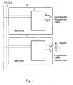
- Fig. 1 shows two known versions of EIB installation devices 20, 21.
- EIB bus lines 3 with installation devices connected to them as participants 20, 21, the bus according to the specifications of the European Installation Bus Association (EIBA) is a twisted pair, via which both information, as well as energy for the on-board power supply of the subscriber devices are.
- the installation devices 20, 21 are not shown in detail by means of a Bus coupling as well as other hardware and software as EIB subscriber devices executed.
- the hardware and software contain a microprocessor 2 including EIB software.
- the microprocessor 2 gives a control signal 9, which by means of a contact 5 or 6 on a signal input 4 of the microprocessor 2 is conductive to activate or deactivate its programming mode.
- the installation device 20 shown in the upper part of FIG. 1 is on the microprocessor 2 a mechanical programming button 5 is connected, with which the control signal 9 can be entered.
- a reed contact to be actuated by means of a magnet 7 6 connected as a programming button with which the control signal 9 can be entered is.
- the disadvantage of these arrangements is that 20 or 21 to certain operating modes or functions, as well as for parameter input - not shown - additional actuating means are required.
- the invention is therefore based on the object of specifying an installation device, allows for the required settings with a single actuator are.
- the proposed installation device is either a mechanical rotary switch or a potentiometer is used to select the mode.
- Fig. 2 shows EIB bus lines 3 to which an installation device 1 and an installation device 10 are connected.
- the installation device 1 contains a microprocessor 2 and peripheral means 13.
- the Microprocessor 2 is part of EIB hardware and software means not shown in detail.
- the peripheral means 13 enable certain operating modes and additional functions.
- Other functions can be activated by means of further rotary switch positions are set, or operating modes or parameters, or combinations thereof become.
- the installation device 10 also contains a microprocessor 2 with signal input 4 to activate the programming mode.
- a coprocessor 11 is available, to which a potentiometer 12 for mode selection is connected.
- the coprocessor 11 is set up for this, depending on a potentiometer position selected in each case N, P, S, T, either the control signal 9 to activate the programming mode to form, so to emulate the usual button signal, and via a To line 14 to the signal input 4 of the microprocessor 2, or a corresponding to form another control signal to one of several defined operating modes, or at least one specific parameter or at least one Activate function of the installation device 10.
- Fig. 3 shows a plan view of a Rotary knob 15 for actuating the potentiometer 12 (FIG. 2) and for setting of the potentiometer on exemplary markings N, P, S, and T on the installation device 10 (Fig. 2).
- P programming mode
- S standard operation
- N normal operation
- T test operation.
Landscapes
- Physics & Mathematics (AREA)
- General Physics & Mathematics (AREA)
- Engineering & Computer Science (AREA)
- Automation & Control Theory (AREA)
- Control By Computers (AREA)
- Information Transfer Systems (AREA)
- Installation Of Indoor Wiring (AREA)
Abstract
Description
- Fig. 1
- bekannte Ausführungen von Installationsgeräten mit Programmiertaster,
- Fig. 2
- erfindungsgemäße Ausführungen des Installationsgeräts, und
- Fig. 3
- eine Draufsicht auf einen Drehknopf zur Betätigung eines Potentiometers und beispielhafte Markierungen am Installationsgerät.
Claims (2)
- Installationsgerät (1), das Hard- und Softwaremittel aufweist, die mindestens einen Mikroprozessor (2) einschließlich einer EIB-Software entsprechend dem EIB(Europäischer Installationsbus)-Standard enthalten, und das für den Anschluß an EIB-Busleitungen (3) eingerichtet ist, wobei der Mikroprozessor (2) einen Signaleingang (4) für die Eingabe eines Steuersignals (9) zur Aktivierung bzw. Deaktivierung seines Programmiermodus hat, und Mittel (8) zur Eingabe des Steuersignals (9) vorhanden sind, dadurch gekennzeichnet, daß als Mittel (8) zur Eingabe des Steuersignals (9) ein Drehschalter (8) angeordnet ist, mit dessen Hilfe durch entsprechende Umschaltung zwischen mehreren wählbaren Schalterstellungen ein vom Mikroprozessor (2) gebildetes Steuersignal (9) entweder zum Signaleingang (4) zur Aktivierung des Programmiermodus leitbar ist, oder auf entsprechende Eingänge peripherer Mittel (13) leitbar ist, um eine von mehreren definierten Betriebsarten, mindestens einen bestimmten Parameter oder mindestens eine Funktion zu aktivieren.
- Installationsgerät (10), das Hard- und Softwaremittel aufweist, die mindestens einen Mikroprozessor (2) einschließlich einer EIB-Software entsprechend dem EIB(Europäischer Installationsbus)-Standard enthalten, und das für den Anschluß an EIB-Busleitungen (3) eingerichtet ist, wobei der Mikroprozessor (2) einen Signaleingang (4) für die Eingabe eines Steuersignals (9) zur Aktivierung bzw. Deaktivierung seines Programmiermodus hat, und Mittel (11, 12) zur Eingabe des Steuersignals (9) vorhanden sind, dadurch gekennzeichnet, daß als Mittel (11, 12) zur Eingabe des Steuersignals (9) ein Coprozessor (11) und ein damit verbundenes Potentiometer (12) vorhanden sind, wobei der Coprozessor (11) dafür eingerichtet ist, abhängig von einer jeweils gewählten Potentiometerstellung (N, P, S, T), entweder das Steuersignal (9) zu bilden und über eine Leitung (14) zum Signaleingang (4) des Mikroprozessors (2) zur Aktivierung seines Programmiermodus zu leiten, oder ein entsprechendes anderes Steuersignal zu bilden, um eine von mehreren definierten Betriebsarten, oder mindestens einen bestimmten Parameter oder mindestens eine Funktion des Installationsgeräts (10) zu aktivieren.
Applications Claiming Priority (2)
| Application Number | Priority Date | Filing Date | Title |
|---|---|---|---|
| DE10100856 | 2001-01-11 | ||
| DE10100856A DE10100856A1 (de) | 2001-01-11 | 2001-01-11 | Installationgsgerät für den Anschluss an EIB-Busleitungen |
Publications (3)
| Publication Number | Publication Date |
|---|---|
| EP1223484A2 true EP1223484A2 (de) | 2002-07-17 |
| EP1223484A3 EP1223484A3 (de) | 2006-06-28 |
| EP1223484B1 EP1223484B1 (de) | 2008-11-05 |
Family
ID=7670152
Family Applications (1)
| Application Number | Title | Priority Date | Filing Date |
|---|---|---|---|
| EP01129612A Expired - Lifetime EP1223484B1 (de) | 2001-01-11 | 2001-12-12 | Installationsgerät für den Anschluss an EIB-Busleitungen |
Country Status (3)
| Country | Link |
|---|---|
| EP (1) | EP1223484B1 (de) |
| AT (1) | ATE413634T1 (de) |
| DE (2) | DE10100856A1 (de) |
Cited By (2)
| Publication number | Priority date | Publication date | Assignee | Title |
|---|---|---|---|---|
| EP2073082A1 (de) | 2007-12-17 | 2009-06-24 | Siemens Aktiengesellschaft | Verfahren zum Initialisieren eines Datenspeichers und Automatisierungskomponente |
| AT12863U1 (de) * | 2006-09-29 | 2013-01-15 | Tridonic Gmbh & Co Kg | Betriebsgerät und verfahren zum betreiben von leuchtmitteln |
Family Cites Families (8)
| Publication number | Priority date | Publication date | Assignee | Title |
|---|---|---|---|---|
| DE3312153A1 (de) * | 1983-04-02 | 1984-10-04 | Grundig E.M.V. Elektro-Mechanische Versuchsanstalt Max Grundig & Co KG, 8510 Fürth | Verfahren und schaltungsanordnung zur tastenabfrage |
| DE3907432C2 (de) * | 1989-03-08 | 1995-03-09 | Miele & Cie | Steuerungsanordnung mit einem Mikrocomputer für Haushaltsgeräte |
| DE4328663C1 (de) * | 1993-08-26 | 1994-06-09 | Grundig Emv | Einrichtung zur Abfrage von Bedienelementen |
| US5619196A (en) * | 1995-12-28 | 1997-04-08 | Universal Electronics Inc. | Single wire keyboard encode and decode circuit |
| DE19605698C1 (de) * | 1996-02-16 | 1997-04-24 | Wieland Elektrische Industrie | Anschlußeinrichtung für ein elektrisches Installationssystem |
| DE29609803U1 (de) * | 1996-06-03 | 1997-10-09 | Zumtobel Licht Gmbh, Dornbirn | Bediengerät zum Steuern mehrerer Verbraucher |
| DE19706957C2 (de) * | 1997-02-21 | 2003-07-03 | Abb Patent Gmbh | Elektronisches Gerät der Gebäudeinstallations- oder -systemtechnik |
| KR20000046877A (ko) * | 1998-12-31 | 2000-07-25 | 구자홍 | 냉장실 과냉/약냉 보상회로 |
-
2001
- 2001-01-11 DE DE10100856A patent/DE10100856A1/de not_active Withdrawn
- 2001-12-12 AT AT01129612T patent/ATE413634T1/de not_active IP Right Cessation
- 2001-12-12 DE DE50114467T patent/DE50114467D1/de not_active Expired - Lifetime
- 2001-12-12 EP EP01129612A patent/EP1223484B1/de not_active Expired - Lifetime
Cited By (2)
| Publication number | Priority date | Publication date | Assignee | Title |
|---|---|---|---|---|
| AT12863U1 (de) * | 2006-09-29 | 2013-01-15 | Tridonic Gmbh & Co Kg | Betriebsgerät und verfahren zum betreiben von leuchtmitteln |
| EP2073082A1 (de) | 2007-12-17 | 2009-06-24 | Siemens Aktiengesellschaft | Verfahren zum Initialisieren eines Datenspeichers und Automatisierungskomponente |
Also Published As
| Publication number | Publication date |
|---|---|
| DE50114467D1 (de) | 2008-12-18 |
| EP1223484A3 (de) | 2006-06-28 |
| ATE413634T1 (de) | 2008-11-15 |
| DE10100856A1 (de) | 2002-07-18 |
| EP1223484B1 (de) | 2008-11-05 |
Similar Documents
| Publication | Publication Date | Title |
|---|---|---|
| DE2824973A1 (de) | Verfahren und vorrichtung zur steuerung der programmwahl bei elektrischen haushaltgeraeten | |
| EP1288763A2 (de) | Vorrichtung zum Steuern eines landwirtschaftlichen Fahrzeugs | |
| DE2834351B2 (de) | Programmwahleinrichtung | |
| DE2809596C2 (de) | ||
| DE69007511T2 (de) | Vorrichtung in einem Kochherd oder in einer Wärmeplatte für Kochzwecke. | |
| DE4220522C2 (de) | Schlauchkennung | |
| EP0718994A2 (de) | Vorrichtung zur Verarbeitung von Tonsignalen | |
| EP1223484A2 (de) | Installationsgerät für den Anschluss an EIB-Busleitungen | |
| CH692317A5 (de) | Hörgerät. | |
| EP2196277A1 (de) | Schweiß- oder Lötvorrichtung mit Bedieneinheit | |
| DE102020128240A1 (de) | Verfahren zur Inbetriebnahme eines Stellantriebs | |
| EP1026041A2 (de) | Bedieneinheit, insbesondere multifunktionale Bedieneinheit | |
| DE69604123T2 (de) | Einrichtung zur Einstellung der Priorität einer elektrischen Steckdose | |
| EP1147895B1 (de) | Bedieneinheit zur Ansteuerung einer Druckmaschine | |
| EP0818945A2 (de) | Elektronisches Stellgerät zum Steuern eines Laststromes | |
| DE102005029180B4 (de) | Elektrische Schaltung zur Beschaltung eines Heizelements | |
| DE202015006817U1 (de) | Elektronisch steuerbare oder regelbare Wasserarmatur oder Wasseraufbereitungsvorrichtung und Bedieninterface | |
| DE9306654U1 (de) | Elektronische Steuervorrichtung zum Steuern der Drehzahl einer landwirtschaftlichen Zugmaschine | |
| DE2412532C2 (de) | Schaltungsanordnung für Fernmeldeanlagen, insbesondere Fernsprechvermittlungsanlagen, in welchen eine durch zwei Steuereinrichtungen fallweise zu belegende Einrichtung vorhanden ist | |
| DE3338350A1 (de) | Hilfseinrichtung zur erzielung optimaler fahrwerte bei mit arbeitsgeraeten zusammenwirkenden ackerschleppern od. dgl. | |
| DE9003169U1 (de) | Infrarot-Fernbedienungsgeber | |
| DE2711246C3 (de) | Einstellbarer Zeitschalter | |
| DE10346161B4 (de) | Programmwahlschalter | |
| DE3930404C2 (de) | Verfahren zum Betrieb einer numerischen Steuerung | |
| DE102007015887A1 (de) | Scheibenwischanlage für ein Kraftfahrzeug |
Legal Events
| Date | Code | Title | Description |
|---|---|---|---|
| PUAI | Public reference made under article 153(3) epc to a published international application that has entered the european phase |
Free format text: ORIGINAL CODE: 0009012 |
|
| AK | Designated contracting states |
Kind code of ref document: A2 Designated state(s): AT BE CH CY DE DK ES FI FR GB GR IE IT LI LU MC NL PT SE TR |
|
| AX | Request for extension of the european patent |
Free format text: AL;LT;LV;MK;RO;SI |
|
| PUAL | Search report despatched |
Free format text: ORIGINAL CODE: 0009013 |
|
| AK | Designated contracting states |
Kind code of ref document: A3 Designated state(s): AT BE CH CY DE DK ES FI FR GB GR IE IT LI LU MC NL PT SE TR |
|
| AX | Request for extension of the european patent |
Extension state: AL LT LV MK RO SI |
|
| 17P | Request for examination filed |
Effective date: 20060805 |
|
| AKX | Designation fees paid |
Designated state(s): AT BE CH DE LI NL |
|
| 17Q | First examination report despatched |
Effective date: 20070809 |
|
| GRAP | Despatch of communication of intention to grant a patent |
Free format text: ORIGINAL CODE: EPIDOSNIGR1 |
|
| GRAS | Grant fee paid |
Free format text: ORIGINAL CODE: EPIDOSNIGR3 |
|
| GRAA | (expected) grant |
Free format text: ORIGINAL CODE: 0009210 |
|
| RAP1 | Party data changed (applicant data changed or rights of an application transferred) |
Owner name: ABB AG |
|
| AK | Designated contracting states |
Kind code of ref document: B1 Designated state(s): AT BE CH DE LI NL |
|
| REG | Reference to a national code |
Ref country code: CH Ref legal event code: EP |
|
| REF | Corresponds to: |
Ref document number: 50114467 Country of ref document: DE Date of ref document: 20081218 Kind code of ref document: P |
|
| NLV1 | Nl: lapsed or annulled due to failure to fulfill the requirements of art. 29p and 29m of the patents act | ||
| PG25 | Lapsed in a contracting state [announced via postgrant information from national office to epo] |
Ref country code: NL Free format text: LAPSE BECAUSE OF FAILURE TO SUBMIT A TRANSLATION OF THE DESCRIPTION OR TO PAY THE FEE WITHIN THE PRESCRIBED TIME-LIMIT Effective date: 20081105 |
|
| BERE | Be: lapsed |
Owner name: ABB A.G. Effective date: 20081231 |
|
| REG | Reference to a national code |
Ref country code: CH Ref legal event code: PL |
|
| PLBE | No opposition filed within time limit |
Free format text: ORIGINAL CODE: 0009261 |
|
| STAA | Information on the status of an ep patent application or granted ep patent |
Free format text: STATUS: NO OPPOSITION FILED WITHIN TIME LIMIT |
|
| PG25 | Lapsed in a contracting state [announced via postgrant information from national office to epo] |
Ref country code: BE Free format text: LAPSE BECAUSE OF NON-PAYMENT OF DUE FEES Effective date: 20081231 |
|
| 26N | No opposition filed |
Effective date: 20090806 |
|
| PG25 | Lapsed in a contracting state [announced via postgrant information from national office to epo] |
Ref country code: CH Free format text: LAPSE BECAUSE OF NON-PAYMENT OF DUE FEES Effective date: 20081231 Ref country code: LI Free format text: LAPSE BECAUSE OF NON-PAYMENT OF DUE FEES Effective date: 20081231 |
|
| PG25 | Lapsed in a contracting state [announced via postgrant information from national office to epo] |
Ref country code: AT Free format text: LAPSE BECAUSE OF NON-PAYMENT OF DUE FEES Effective date: 20081212 |
|
| REG | Reference to a national code |
Ref country code: DE Ref legal event code: R084 Ref document number: 50114467 Country of ref document: DE |
|
| REG | Reference to a national code |
Ref country code: DE Ref legal event code: R081 Ref document number: 50114467 Country of ref document: DE Owner name: ABB SCHWEIZ AG, CH Free format text: FORMER OWNER: ABB AG, 68309 MANNHEIM, DE |
|
| PGFP | Annual fee paid to national office [announced via postgrant information from national office to epo] |
Ref country code: DE Payment date: 20201211 Year of fee payment: 20 |
|
| REG | Reference to a national code |
Ref country code: DE Ref legal event code: R071 Ref document number: 50114467 Country of ref document: DE |