EP1223389A1 - Refrigerating device - Google Patents
Refrigerating device Download PDFInfo
- Publication number
- EP1223389A1 EP1223389A1 EP00966427A EP00966427A EP1223389A1 EP 1223389 A1 EP1223389 A1 EP 1223389A1 EP 00966427 A EP00966427 A EP 00966427A EP 00966427 A EP00966427 A EP 00966427A EP 1223389 A1 EP1223389 A1 EP 1223389A1
- Authority
- EP
- European Patent Office
- Prior art keywords
- refrigerant
- amount
- cop
- capacity
- refrigerant circuit
- Prior art date
- Legal status (The legal status is an assumption and is not a legal conclusion. Google has not performed a legal analysis and makes no representation as to the accuracy of the status listed.)
- Granted
Links
Images




Classifications
-
- C—CHEMISTRY; METALLURGY
- C09—DYES; PAINTS; POLISHES; NATURAL RESINS; ADHESIVES; COMPOSITIONS NOT OTHERWISE PROVIDED FOR; APPLICATIONS OF MATERIALS NOT OTHERWISE PROVIDED FOR
- C09K—MATERIALS FOR MISCELLANEOUS APPLICATIONS, NOT PROVIDED FOR ELSEWHERE
- C09K5/00—Heat-transfer, heat-exchange or heat-storage materials, e.g. refrigerants; Materials for the production of heat or cold by chemical reactions other than by combustion
- C09K5/02—Materials undergoing a change of physical state when used
- C09K5/04—Materials undergoing a change of physical state when used the change of state being from liquid to vapour or vice versa
- C09K5/041—Materials undergoing a change of physical state when used the change of state being from liquid to vapour or vice versa for compression-type refrigeration systems
- C09K5/044—Materials undergoing a change of physical state when used the change of state being from liquid to vapour or vice versa for compression-type refrigeration systems comprising halogenated compounds
- C09K5/045—Materials undergoing a change of physical state when used the change of state being from liquid to vapour or vice versa for compression-type refrigeration systems comprising halogenated compounds containing only fluorine as halogen
-
- F—MECHANICAL ENGINEERING; LIGHTING; HEATING; WEAPONS; BLASTING
- F25—REFRIGERATION OR COOLING; COMBINED HEATING AND REFRIGERATION SYSTEMS; HEAT PUMP SYSTEMS; MANUFACTURE OR STORAGE OF ICE; LIQUEFACTION SOLIDIFICATION OF GASES
- F25B—REFRIGERATION MACHINES, PLANTS OR SYSTEMS; COMBINED HEATING AND REFRIGERATION SYSTEMS; HEAT PUMP SYSTEMS
- F25B39/00—Evaporators; Condensers
- F25B39/04—Condensers
-
- F—MECHANICAL ENGINEERING; LIGHTING; HEATING; WEAPONS; BLASTING
- F25—REFRIGERATION OR COOLING; COMBINED HEATING AND REFRIGERATION SYSTEMS; HEAT PUMP SYSTEMS; MANUFACTURE OR STORAGE OF ICE; LIQUEFACTION SOLIDIFICATION OF GASES
- F25B—REFRIGERATION MACHINES, PLANTS OR SYSTEMS; COMBINED HEATING AND REFRIGERATION SYSTEMS; HEAT PUMP SYSTEMS
- F25B9/00—Compression machines, plants or systems, in which the refrigerant is air or other gas of low boiling point
- F25B9/002—Compression machines, plants or systems, in which the refrigerant is air or other gas of low boiling point characterised by the refrigerant
-
- F—MECHANICAL ENGINEERING; LIGHTING; HEATING; WEAPONS; BLASTING
- F25—REFRIGERATION OR COOLING; COMBINED HEATING AND REFRIGERATION SYSTEMS; HEAT PUMP SYSTEMS; MANUFACTURE OR STORAGE OF ICE; LIQUEFACTION SOLIDIFICATION OF GASES
- F25B—REFRIGERATION MACHINES, PLANTS OR SYSTEMS; COMBINED HEATING AND REFRIGERATION SYSTEMS; HEAT PUMP SYSTEMS
- F25B9/00—Compression machines, plants or systems, in which the refrigerant is air or other gas of low boiling point
- F25B9/002—Compression machines, plants or systems, in which the refrigerant is air or other gas of low boiling point characterised by the refrigerant
- F25B9/006—Compression machines, plants or systems, in which the refrigerant is air or other gas of low boiling point characterised by the refrigerant the refrigerant containing more than one component
-
- C—CHEMISTRY; METALLURGY
- C09—DYES; PAINTS; POLISHES; NATURAL RESINS; ADHESIVES; COMPOSITIONS NOT OTHERWISE PROVIDED FOR; APPLICATIONS OF MATERIALS NOT OTHERWISE PROVIDED FOR
- C09K—MATERIALS FOR MISCELLANEOUS APPLICATIONS, NOT PROVIDED FOR ELSEWHERE
- C09K2205/00—Aspects relating to compounds used in compression type refrigeration systems
- C09K2205/24—Only one single fluoro component present
-
- F—MECHANICAL ENGINEERING; LIGHTING; HEATING; WEAPONS; BLASTING
- F25—REFRIGERATION OR COOLING; COMBINED HEATING AND REFRIGERATION SYSTEMS; HEAT PUMP SYSTEMS; MANUFACTURE OR STORAGE OF ICE; LIQUEFACTION SOLIDIFICATION OF GASES
- F25B—REFRIGERATION MACHINES, PLANTS OR SYSTEMS; COMBINED HEATING AND REFRIGERATION SYSTEMS; HEAT PUMP SYSTEMS
- F25B13/00—Compression machines, plants or systems, with reversible cycle
-
- F—MECHANICAL ENGINEERING; LIGHTING; HEATING; WEAPONS; BLASTING
- F25—REFRIGERATION OR COOLING; COMBINED HEATING AND REFRIGERATION SYSTEMS; HEAT PUMP SYSTEMS; MANUFACTURE OR STORAGE OF ICE; LIQUEFACTION SOLIDIFICATION OF GASES
- F25B—REFRIGERATION MACHINES, PLANTS OR SYSTEMS; COMBINED HEATING AND REFRIGERATION SYSTEMS; HEAT PUMP SYSTEMS
- F25B2400/00—Component parts or details not otherwise provided for in this subclass
- F25B2400/12—Inflammable refrigerants
-
- F—MECHANICAL ENGINEERING; LIGHTING; HEATING; WEAPONS; BLASTING
- F25—REFRIGERATION OR COOLING; COMBINED HEATING AND REFRIGERATION SYSTEMS; HEAT PUMP SYSTEMS; MANUFACTURE OR STORAGE OF ICE; LIQUEFACTION SOLIDIFICATION OF GASES
- F25B—REFRIGERATION MACHINES, PLANTS OR SYSTEMS; COMBINED HEATING AND REFRIGERATION SYSTEMS; HEAT PUMP SYSTEMS
- F25B2500/00—Problems to be solved
- F25B2500/01—Geometry problems, e.g. for reducing size
-
- Y—GENERAL TAGGING OF NEW TECHNOLOGICAL DEVELOPMENTS; GENERAL TAGGING OF CROSS-SECTIONAL TECHNOLOGIES SPANNING OVER SEVERAL SECTIONS OF THE IPC; TECHNICAL SUBJECTS COVERED BY FORMER USPC CROSS-REFERENCE ART COLLECTIONS [XRACs] AND DIGESTS
- Y02—TECHNOLOGIES OR APPLICATIONS FOR MITIGATION OR ADAPTATION AGAINST CLIMATE CHANGE
- Y02P—CLIMATE CHANGE MITIGATION TECHNOLOGIES IN THE PRODUCTION OR PROCESSING OF GOODS
- Y02P20/00—Technologies relating to chemical industry
- Y02P20/10—Process efficiency
Definitions
- the present invention relates to a refrigeration unit, and more particularly relates to a refrigeration unit with use of R32 (chemical formula: CH 2 F 2 ) as a refrigerant alternative to R22 (chemical formula:CHCIF 2 ) or with use of mixed refrigerants containing at least 70 weight percent R32.
- R32 chemical formula: CH 2 F 2
- CHCIF 2 chemical formula:CHCIF 2
- Global environmental challenges relating to refrigeration units or air conditioners that perform a refrigerating -cycle with use of refrigerants include (1) ozonosphere protection, (2) energy conservation, (3) measures against global warming (emission control of CO 2 ant the like), and (4) recycling of resources.
- R22 HFC22
- ODP Ozone Depletion Potential
- Some refrigeration units for performing a refrigerating cycle with use of R410A or R407C have achieved the same COP (Coefficient of Performance) as R22, and have already been manufactured as products.
- TEWI Total Equivalent Warming Impact
- the TEWI is expressed as the sum of an impact of refrigerants released to the air (direct impact) and energy consumption of a unit (indirect impact).
- the direct impact includes GWP (Global Warming Potential), while the indirect impact includes a reciprocal of COP. Consequently, in order to prevent global warming, or equivalently, to decrease the value of TEWI, it is necessary to select refrigerants having a small GWP value and a large COP value.
- the GWP values of R407C and R410A are 1980 and 2340, respectively, which are slightly larger than the GWP value 1900 of R22. Accordingly, R32 (HFC32) is expected as a prospective refrigerant having a small GWP value for prevention of global warming. R32 has the GWP value of 650, which is about one third of the GWP values 1900, 1980 and 2340 of R22, R407C and R410A, and therefore considered to be an extremely small value.
- the COP values of R407C and R410A are approximately equal to the COP value of R22, whereas the COP value of R32 is not larger than that of R22. More particularly, although the refrigeration unit for performing a refrigerating cycle with use of R32 is theoretically expected a high COP value because of the characteristics of R32, any actual ' result that significantly exceeds the COP of R22 is not provided so far. Also, use of R32 brings about a phenomenon of higher pressure and higher discharge temperature compared to use of R22. In addition to that, there is a problem of difficulty in reaching a safety consensus because R32 has slight flammability. Because of this reason, the industrial society has not adopted R32 as an alternative refrigerant product.
- COP Coefficient of Performance
- GWP Global Warming Potential
- the present invention is invented based on finding by an inventor of the present invention that a tendency for the COP of a refrigeration unit to change in response to an amount of a refrigerant (the total amount for filling a refrigerant circuit) is considerably different in types of refrigerants, especially between R32 and other refrigerants including R410A. More particularly, as shown in Fig. 1a, in the case of using, for example, R410A, there is a tendency that the COP gradually rises and saturates with increase of an amount of the refrigerant within the range shown in the drawing.
- R32 has GWP much lower than that of conventional R22 and R410A (about one third). Further, adequate selection of an amount of the refrigerant enables R32 to obtain COP higher than that of R410A and R22. This makes TEWI (Total Equivalent Warming Impact) of R32 smaller than the TEWI of R22 and R410A, thereby proving superiority of R32 in global warming characteristics compared to R22 and R410A.
- TEWI Total Equivalent Warming Impact
- the present invention provides a refrigeration unit for performing a refrigerating cycle by circulating R32 as a refrigerant through a refrigerant circuit comprising a compressor, a condenser, expansion means, and an evaporator, wherein an amount of R32 for filling the refrigerant circuit is in a range of 120g to 450g per kW of refrigerating capacity.
- an amount of R32 for filling the refrigerant circuit being in the range of 120g to 450g per kW of refrigerating capacity implements high COP.
- measuring method of refrigerating capacity shall conform to the regulations of Japan Industrial Standard (JIS) C9612.
- an amount of R32 for filling is "in the range of 120g to 450g per kW of refrigerating capacity"
- the total amount of R32 for filling the refrigerant circuit is, for example, 600g to 2250g if the refrigerating capacity is 5kW.
- the present invention also provides a refrigeration unit for performing a refrigerating cycle by circulating R32 as a refrigerant through a refrigerant circuit comprising a compressor, a condenser, expansion means, and an evaporator, wherein an amount of R32 for filling the refrigerant circuit is in a range of 400g to 750g per liter of unobstructed capacity of the condenser.
- an amount of R32 for filling the refrigerant circuit being in the range of 400g to 750g per liter unobstructed capacity of the condenser implements high COP.
- an amount of R32 for filling is "in a range of 400g to 750g per liter of unobstructed capacity of the condenser"
- the total amount of R32 for filling the refrigerant circuit is, for example, in the range of 600g to 1125g if the unobstructed capacity of the condenser is 1.5 liter.
- the principles of the invention are not only applicable to a single refrigerant of R32, but also applicable to mixed refrigerants containing at least 70 weight percent R32.
- the present invention also provides a refrigeration unit for performing a refrigerating cycle by circulating mixed refrigerants containing at least 70 weight percent R32 through a refrigerant circuit comprising a compressor, a condenser, expansion means, and an evaporator, wherein an amount of the R32 for filling the refrigerant circuit is in a range of 84g to 450g per kW of refrigerating capacity.
- an amount of R32 for filling the refrigerant circuit being in the range of 84g to 450g per kW of refrigerating capacity implements high COP.
- the present invention also provides a refrigeration unit for performing a refrigerating cycle by circulating mixed refrigerants containing at least 70 weight percent R32 through a refrigerant circuit comprising a compressor, a condenser, expansion means, and an evaporator, wherein an amount of the R32 for filling the refrigerant circuit is in a range of 280g to 750g per liter of unobstructed capacity of the condenser.
- an amount of R32 for filling the refrigerant circuit being in the range of 280g to 750g per liter of unobstructed capacity of the condenser implements high COP.
- Fig. 2 shows outline structure of a heat pump type air conditioner in one embodiment of the present invention.
- an outdoor unit 20 and an indoor unit 1 are connected by refrigerant pipes 41 and 42 to constitute a refrigerant circuit, through which R32 is circulated as a refrigerant.
- the indoor unit 1 accommodates an indoor heat exchanger 2.
- the outdoor unit 20 accommodates a compressor 23 for compressing and discharging a refrigerant (R32), a four-pass diverter valve 25 for diverting refrigerant passes, an outdoor heat exchanger 22, a motor-driven expansion valve 26, and an accumulator 24 for vapor-liquid separation of the circulated refrigerant.
- a refrigerant discharged by the compressor 23 is sent, as shown with a solid line in Fig. 2, through a pipe 31, the four-pass diverter valve 25 and a pipe 33, to the outdoor heat exchanger 22 functioning as a condenser.
- the refrigerant condensed in the outdoor heat exchanger 22 is sent through a pipe 36, an expansion valve 26 for tightening the pass to expand the refrigerant and a pipe 42, to the indoor heat exchanger 2 functioning as an evaporator.
- the refrigerant evaporated in the indoor heat exchanger 2 is returned through a pipe 41, a pipe 34, the four-pass diverter valve 25, a pipe 32, an accumulator 24 and a pipe 35, to the compressor 23.
- the four-pass diverter valve 25 is switched to send a refrigerant discharged by the compressor 23 to the indoor heat exchanger 2 functioning as a condenser through the pipe 31, the four-pass diverter valve 25, the pipe 34 and the pipe 41, as shown with a dotted line in Fig. 2.
- the refrigerant condensed in the indoor heat exchanger 2 is sent to the pipe 42, the expansion valve 26 in a full-open state, the pipe 36, and the outdoor heat exchanger 22 functioning as an evaporator.
- the refrigerant evaporated in the outdoor heat exchanger 22 is returned through the pipe 33, the four-pass diverter valve 25, the pipe 32, the accumulator 24 and the pipe 35, to the compressor 23.
- COP Coefficient of Performance
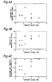
- the inventor of the present invention prepared air conditioners different in capacity class from 2.2kW to 5.0kW with unobstructed capacity of the indoor heat exchanger 2 and unobstructed capacity of the outdoor heat exchanger 22 changed in variations as shown in Figs. 4A and 4B.
- Fig. 4C shows comparison of the unobstructed capacity of the outdoor heat exchanger 22 and the unobstructed capacity of the indoor heat exchanger 2.
- Unobstructed capacity of the entire refrigerant circuit is changed according to setting of the unobstructed capacity of the indoor heat exchanger 2 and the unobstructed capacity of the outdoor heat exchanger 22.
- unobstructed capacity of the outdoor heat exchanger 22 is set to 1.45 liter and unobstructed capacity of the indoor heat exchanger 2 is set to 0.47 liter.
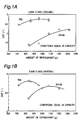
- COP was measured with an amount of a refrigerant (the total amount for filling the refrigerant circuit) changed. The result thereof is shown in Figs. 1A and 1B, where Fig. 1A shows COP in cooling operation and Fig. 1B shows COP in heating operation. As shown in Fig.
- COP with use of R32 and COP with use of R410A were compared, and the result as shown in Figs. 3A and 3B were obtained.
- An amount of the refrigerant in the case of using R32 was optimized in the range of 60wt.% to 80wt.% against an amount of the refrigerant in the case of using R410A.
- Fig. 3A shows that the COP with use of R32 was 108.1% when using the COP value with use of R410A as a reference (100%).
- Fig. 3B shows that the COP with use of R410A was 4.00 whereas the COP with use of R32 was 4.33.
- Figs. 1A and 1B also indicate that an optimum amount of the refrigerant that gives a COP peak in the case of using R32 was 960g in cooling operation and 840g in heating operation, whereas an optimum amount of the refrigerant in the case of using R410A was 1300g in cooling operation and 11008 in heating operation.
- a cooling/heating ratio of an optimum amount of the refrigerant in the case of using R32 is closer to 1 compared to the case of using R410A. This saves a cooling/heating refrigerant adjusting container and implements decrease of accumulator capacity.
- the present invention is naturally not limited thereto.
- the present invention is broadly applicable to the units for performing a refrigerating cycle with use of R32 as a refrigerant.
- the principles of the present invention are not only applicable to a single refrigerant of R32, but also applicable to mixed refrigerants containing at least 70 weight percent R32.
- a compound of R32 and R125 is regarded as a mixed refrigerant.
- the range having 70 weight percent R32 or less is an azeotropic range where the liquid composition and the generated vapor composition are identical, while other ranges are categorized as a nonazeotropic range.
- properties of R32 are clarified, and in the nonazeotropic range, the properties of R32 become remarkable.
- Fig. 5 shows relationship between a content of R32 in mixed refrigerants containing R125 and energy efficiency.
- a content of R32 equal to 70 weight percent or more
- rise of the energy efficiency is remarkable.
- a content of R32 beyond approx. 80 weight percent the energy efficiency exceeds the energy efficiency of R22. Therefore, with a content of R32 equal to 70 weight percent or more, high COP is obtained.
- a single refrigerant of R32 or mixed refrigerants containing at least 70 weight percent R32 are, as shown in Figs. 1 and 5, have the COP equal to or higher than that of conventional refrigerants such as R22.
- the GWP (Global Warming Potential) of R32 is as low as approx. one third of the GWP of conventional refrigerants such as R22 as stated before. Consequently, the TEWI (Total Equivalent Warming Impact) of R32 is lower than the TEWI of R22 and R410A (lowering rate of 10 to 20%), thereby proving superiority of R32 in global warming characteristics compared to R22 and R410A.
- R32 refrigerant and mixed refrigerants containing at least 70 weight percent R32 are not only free from depleting ozonosphere but also small in GWP (Global Warming Potential) and TEWI (Total Equivalent Warming Impact) and large in COP (Coefficient of Performance), which makes them energy-saving refrigerants against global warming.
- GWP Global Warming Potential
- TEWI Total Equivalent Warming Impact
- COP Coefficient of Performance
- a refrigeration unit with use of R32 refrigerant is, as shown in Fig. 6, capable of obtaining high COP with an amount of the filling refrigerant smaller than that of R410 refrigerant, and small in difference between an optimum amount of the refrigerant in cooling and an optimum amount of the refrigerant in heating.
- R32 refrigerant is high in heat transfer capacity compared to R410A refrigerant, capable of implementing sufficient capacity with a small amount of the filling refrigerant, and small in difference between an optimum amount of the refrigerant in cooling and an optimum amount of the refrigerant in heating compared to R410 refrigerant, which enables reduction of an amount of the refrigerant for use in the refrigeration unit.
- Fig. 7 shows capacity of an accumulator and a receiver against the refrigerating capacity of each of the refrigerants R32, R410A and R22.
- the refrigeration unit with refrigerating capacity of 4kW or less needs neither an accumulator nor a receiver. Therefore, the refrigeration unit with use of R32 saves an accumulator and a receiver, which enables reduction of production costs of the refrigeration unit as well as downsizing of the refrigeration unit.
Landscapes
- Engineering & Computer Science (AREA)
- Physics & Mathematics (AREA)
- Thermal Sciences (AREA)
- Mechanical Engineering (AREA)
- Chemical & Material Sciences (AREA)
- General Engineering & Computer Science (AREA)
- Chemical Kinetics & Catalysis (AREA)
- Organic Chemistry (AREA)
- Materials Engineering (AREA)
- Combustion & Propulsion (AREA)
- Compression-Type Refrigeration Machines With Reversible Cycles (AREA)
- Air Conditioning Control Device (AREA)
- Devices That Are Associated With Refrigeration Equipment (AREA)
Abstract
Description
- The present invention relates to a refrigeration unit, and more particularly relates to a refrigeration unit with use of R32 (chemical formula: CH2F2) as a refrigerant alternative to R22 (chemical formula:CHCIF2) or with use of mixed refrigerants containing at least 70 weight percent R32.
- Global environmental challenges relating to refrigeration units or air conditioners that perform a refrigerating -cycle with use of refrigerants include (1) ozonosphere protection, (2) energy conservation, (3) measures against global warming (emission control of CO2 ant the like), and (4) recycling of resources.
- In the global environmental challenges, particularly in view of the ozonosphere protection, R22 (HFC22) is high in ODP (Ozone Depletion Potential) so that it is not regarded as a preferable refrigerant. Accordingly, as prospective refrigerants alternative to R22, there are R410A (HFC32:HFC125 =50:50 (weight ratio)) and R407C (HFC32:HFC125:HFC134a =23:25:52 (weight ratio)). Some refrigeration units for performing a refrigerating cycle with use of R410A or R407C have achieved the same COP (Coefficient of Performance) as R22, and have already been manufactured as products.
- As for energy conservation, there has already been notified that designated air conditioners are required to improve COP by approx. 4% by the end of September, 2004 (Notification No. 190 of the Ministry of International Trade and Industry based on "Law concerning the Rational Use of Energy"). Therefore, in view of energy conservation, it is necessary to use refrigerants having a large COP value.
- In addition, demands for prevention of global warming is becoming harder. In the field of refrigeration units or air conditioners, an index to global warming called TEWI (Total Equivalent Warming Impact) is used to evaluate the refrigeration units and air conditioners. The TEWI is expressed as the sum of an impact of refrigerants released to the air (direct impact) and energy consumption of a unit (indirect impact). The direct impact includes GWP (Global Warming Potential), while the indirect impact includes a reciprocal of COP. Consequently, in order to prevent global warming, or equivalently, to decrease the value of TEWI, it is necessary to select refrigerants having a small GWP value and a large COP value.
- The GWP values of R407C and R410A are 1980 and 2340, respectively, which are slightly larger than the GWP value 1900 of R22. Accordingly, R32 (HFC32) is expected as a prospective refrigerant having a small GWP value for prevention of global warming. R32 has the GWP value of 650, which is about one third of the GWP values 1900, 1980 and 2340 of R22, R407C and R410A, and therefore considered to be an extremely small value.
- The COP values of R407C and R410A are approximately equal to the COP value of R22, whereas the COP value of R32 is not larger than that of R22. More particularly, although the refrigeration unit for performing a refrigerating cycle with use of R32 is theoretically expected a high COP value because of the characteristics of R32, any actual ' result that significantly exceeds the COP of R22 is not provided so far. Also, use of R32 brings about a phenomenon of higher pressure and higher discharge temperature compared to use of R22. In addition to that, there is a problem of difficulty in reaching a safety consensus because R32 has slight flammability. Because of this reason, the industrial society has not adopted R32 as an alternative refrigerant product.
- Accordingly, it is an object of the present invention to provide an energy-saving refrigeration unit against global warming that is capable of achieving high COP (Coefficient of Performance) with use of R32 having a small GWP (Global Warming Potential) as a refrigerant.
- The present invention is invented based on finding by an inventor of the present invention that a tendency for the COP of a refrigeration unit to change in response to an amount of a refrigerant (the total amount for filling a refrigerant circuit) is considerably different in types of refrigerants, especially between R32 and other refrigerants including R410A. More particularly, as shown in Fig. 1a, in the case of using, for example, R410A, there is a tendency that the COP gradually rises and saturates with increase of an amount of the refrigerant within the range shown in the drawing. On the contrary, in the case of using R32, there is a tendency that the COP marks a peak with change of an amount of the refrigerant, and then shows a sharp drop once an amount of the refrigerant is out of the range that gives the peak. Conventionally, the reason why use of R32 fails to provide high COP compared to use of R410A is because the refrigerants are used in the range that is relatively large in amount of the refrigerant (1200g to 1300g in the case shown in Fig. 1a). The notable point here is that a peak value of the COP in the case of using R32 with change in amount of the refrigerant is much higher than the COP in the case of using R410A with an optimum amount of the refrigerant (1300g in the case of Fig. 1a). This indicates that use of R32 with an amount of the refrigerant set in an appropriate range enables achievement of high COP.
- As described above, R32 has GWP much lower than that of conventional R22 and R410A (about one third). Further, adequate selection of an amount of the refrigerant enables R32 to obtain COP higher than that of R410A and R22. This makes TEWI (Total Equivalent Warming Impact) of R32 smaller than the TEWI of R22 and R410A, thereby proving superiority of R32 in global warming characteristics compared to R22 and R410A.
- The present invention provides a refrigeration unit for performing a refrigerating cycle by circulating R32 as a refrigerant through a refrigerant circuit comprising a compressor, a condenser, expansion means, and an evaporator, wherein an amount of R32 for filling the refrigerant circuit is in a range of 120g to 450g per kW of refrigerating capacity.
- As shown above, an amount of R32 for filling the refrigerant circuit being in the range of 120g to 450g per kW of refrigerating capacity implements high COP.
- Herein, measuring method of refrigerating capacity (kW) shall conform to the regulations of Japan Industrial Standard (JIS) C9612.
- It is noted that since an amount of R32 for filling is "in the range of 120g to 450g per kW of refrigerating capacity", the total amount of R32 for filling the refrigerant circuit is, for example, 600g to 2250g if the refrigerating capacity is 5kW.
- The present invention also provides a refrigeration unit for performing a refrigerating cycle by circulating R32 as a refrigerant through a refrigerant circuit comprising a compressor, a condenser, expansion means, and an evaporator, wherein an amount of R32 for filling the refrigerant circuit is in a range of 400g to 750g per liter of unobstructed capacity of the condenser.
- As shown above, an amount of R32 for filling the refrigerant circuit being in the range of 400g to 750g per liter unobstructed capacity of the condenser implements high COP.
- It is noted that the reason why an amount of R32 for filling the refrigerant circuit is prescribed as "per liter unobstructed capacity of the condenser" is because the unobstructed capacity of the condenser is dominant over an amount of the filling refrigerant.
- Also, since an amount of R32 for filling is "in a range of 400g to 750g per liter of unobstructed capacity of the condenser", the total amount of R32 for filling the refrigerant circuit is, for example, in the range of 600g to 1125g if the unobstructed capacity of the condenser is 1.5 liter.
- The principles of the invention are not only applicable to a single refrigerant of R32, but also applicable to mixed refrigerants containing at least 70 weight percent R32.
- The present invention also provides a refrigeration unit for performing a refrigerating cycle by circulating mixed refrigerants containing at least 70 weight percent R32 through a refrigerant circuit comprising a compressor, a condenser, expansion means, and an evaporator, wherein an amount of the R32 for filling the refrigerant circuit is in a range of 84g to 450g per kW of refrigerating capacity.
- In the case of using mixed refrigerants containing at least 70 weight percent R32 as shown above, an amount of R32 for filling the refrigerant circuit being in the range of 84g to 450g per kW of refrigerating capacity implements high COP.
- The present invention also provides a refrigeration unit for performing a refrigerating cycle by circulating mixed refrigerants containing at least 70 weight percent R32 through a refrigerant circuit comprising a compressor, a condenser, expansion means, and an evaporator, wherein an amount of the R32 for filling the refrigerant circuit is in a range of 280g to 750g per liter of unobstructed capacity of the condenser.
- In the case of using mixed refrigerants containing at least 70 weight percent R32 as shown above, an amount of R32 for filling the refrigerant circuit being in the range of 280g to 750g per liter of unobstructed capacity of the condenser implements high COP.
-
- Figs. 1A and 1B are views showing the results of measuring COP in the case of using R32 as a refrigerant and COP in the case of using R410A as a refrigerant, each with an amount of the refrigerant (the total amount for filling the refrigerant circuit) changed in cooling operation, where Fig. 1A shows the result in cooling operation and Fig. 1B shows the result in heating operation;
- Fig. 2 is a view showing outline structure of a heat pump type air conditioner in one embodiment of the present invention;
- Figs. 3A and 3B are views showing comparison of COP in the case of using R32 and COP in the case of using R410A under conditions of equal capacity (equal in compressor capacity), where Fig. 3A is a view showing comparison of COP of R32 and R410A in percentage, and Fig. 3B is a view showing the comparison in measured values;
- Figs. 4A, 4B and 4C are views each showing setting values of unobstructed capacity of an indoor heat exchanger and unobstructed capacity of an outdoor heat exchanger of the air conditioner:
- Fig. 5 is a view showing a content and energy efficiency of R32 in mixed refrigerants of R32 and R125;
- Fig. 6 is a view showing COP against an amount of refrigerants R32 and R410A in cooling and heating; and
- Fig. 7 is a view showing capacity of an accumulator and a receiver against the refrigerating capacity of each of refrigerants R32, R410A and R22.
-
- Detailed description will now be given of a refrigeration unit in embodiments of the present invention with reference to drawings.
- Fig. 2 shows outline structure of a heat pump type air conditioner in one embodiment of the present invention. In the air conditioner, an
outdoor unit 20 and anindoor unit 1 are connected byrefrigerant pipes indoor unit 1 accommodates anindoor heat exchanger 2. Theoutdoor unit 20 accommodates acompressor 23 for compressing and discharging a refrigerant (R32), a four-pass diverter valve 25 for diverting refrigerant passes, anoutdoor heat exchanger 22, a motor-drivenexpansion valve 26, and anaccumulator 24 for vapor-liquid separation of the circulated refrigerant. - In cooling operation for performing the refrigerating cycle, by switching setting of the four-
pass diverter valve 25, a refrigerant discharged by thecompressor 23 is sent, as shown with a solid line in Fig. 2, through apipe 31, the four-pass diverter valve 25 and apipe 33, to theoutdoor heat exchanger 22 functioning as a condenser. The refrigerant condensed in theoutdoor heat exchanger 22 is sent through apipe 36, anexpansion valve 26 for tightening the pass to expand the refrigerant and apipe 42, to theindoor heat exchanger 2 functioning as an evaporator. Further, the refrigerant evaporated in theindoor heat exchanger 2 is returned through apipe 41, apipe 34, the four-pass diverter valve 25, apipe 32, anaccumulator 24 and apipe 35, to thecompressor 23. In heating operation, the four-pass diverter valve 25 is switched to send a refrigerant discharged by thecompressor 23 to theindoor heat exchanger 2 functioning as a condenser through thepipe 31, the four-pass diverter valve 25, thepipe 34 and thepipe 41, as shown with a dotted line in Fig. 2. The refrigerant condensed in theindoor heat exchanger 2 is sent to thepipe 42, theexpansion valve 26 in a full-open state, thepipe 36, and theoutdoor heat exchanger 22 functioning as an evaporator. Further, the refrigerant evaporated in theoutdoor heat exchanger 22 is returned through thepipe 33, the four-pass diverter valve 25, thepipe 32, theaccumulator 24 and thepipe 35, to thecompressor 23. - For evaluating COP (Coefficient of Performance) of the air conditioner, the inventor of the present invention prepared air conditioners different in capacity class from 2.2kW to 5.0kW with unobstructed capacity of the
indoor heat exchanger 2 and unobstructed capacity of theoutdoor heat exchanger 22 changed in variations as shown in Figs. 4A and 4B. Fig. 4C shows comparison of the unobstructed capacity of theoutdoor heat exchanger 22 and the unobstructed capacity of theindoor heat exchanger 2. Unobstructed capacity of the entire refrigerant circuit is changed according to setting of the unobstructed capacity of theindoor heat exchanger 2 and the unobstructed capacity of theoutdoor heat exchanger 22. - For example, for the 5.0kW class air conditioner, unobstructed capacity of the
outdoor heat exchanger 22 is set to 1.45 liter and unobstructed capacity of theindoor heat exchanger 2 is set to 0.47 liter. In the 5.0kW class air conditioner, COP was measured with an amount of a refrigerant (the total amount for filling the refrigerant circuit) changed. The result thereof is shown in Figs. 1A and 1B, where Fig. 1A shows COP in cooling operation and Fig. 1B shows COP in heating operation. As shown in Fig. 1A, in cooling operation, relatively high peak COP values of 2.7 to 2.8 were obtained when an amount of the refrigerant was 960g, whereas the air conditioner with the same capacity of 5.0kW and use of R410A showed COP of 2.2 at most (when an amount of the refrigerant was 1300g). - Thus, it was attempted to find the range of an amount of the refrigerant that gives a COP peak under each condition in the case of using R32. As a result, it was found that the COP peak is given when an amount of R32 for filling the refrigerant circuit is in the range of 120g to 450g per kW of refrigerating capacity, or an amount of R32 for filling the refrigerant circuit is in the range of 400g to 750g per liter of unobstructed capacity of the
outdoor heat exchanger 22. - Also, in the case of the same capacity (equal in compressor capacity) in the range from 2.2kW to 5.0kW, COP with use of R32 and COP with use of R410A were compared, and the result as shown in Figs. 3A and 3B were obtained. An amount of the refrigerant in the case of using R32 was optimized in the range of 60wt.% to 80wt.% against an amount of the refrigerant in the case of using R410A. Fig. 3A shows that the COP with use of R32 was 108.1% when using the COP value with use of R410A as a reference (100%). Fig. 3B shows that the COP with use of R410A was 4.00 whereas the COP with use of R32 was 4.33. This implies that use of R32 with an amount of the refrigerant set in an appropriate range enables achievement of the COP much higher than that in the case of using R410A. The improvement of the COP may be attributed to small pressure loss and improved heat transfer of the refrigerant in addition to improved physical properties of the refrigerant.
- Figs. 1A and 1B also indicate that an optimum amount of the refrigerant that gives a COP peak in the case of using R32 was 960g in cooling operation and 840g in heating operation, whereas an optimum amount of the refrigerant in the case of using R410A was 1300g in cooling operation and 11008 in heating operation. As this result implies, a cooling/heating ratio of an optimum amount of the refrigerant in the case of using R32 is closer to 1 compared to the case of using R410A. This saves a cooling/heating refrigerant adjusting container and implements decrease of accumulator capacity.
- Although in the embodiment, description was made of the heat pump type air conditioner, the present invention is naturally not limited thereto. The present invention is broadly applicable to the units for performing a refrigerating cycle with use of R32 as a refrigerant.
- Also the principles of the present invention are not only applicable to a single refrigerant of R32, but also applicable to mixed refrigerants containing at least 70 weight percent R32. For example, a compound of R32 and R125 is regarded as a mixed refrigerant. In the mixed refrigerants of R32 and R125, the range having 70 weight percent R32 or less is an azeotropic range where the liquid composition and the generated vapor composition are identical, while other ranges are categorized as a nonazeotropic range. With increase of a content of R32, properties of R32 are clarified, and in the nonazeotropic range, the properties of R32 become remarkable.
- Experiments performed by the present inventor confirmed that in the case of using mixed refrigerants containing at least 70 weight percent R32, high COP is obtained if an amount of R32 for filling the refrigerant circuit is in the range of 84g to 450g per kW of refrigerating capacity, or an amount of R32 for filling the refrigerant circuit is in the range of 280g to 750g per liter of unobstructed capacity of the condenser.
- Fig. 5 shows relationship between a content of R32 in mixed refrigerants containing R125 and energy efficiency. With a content of R32 equal to 70 weight percent or more, rise of the energy efficiency is remarkable. With a content of R32 beyond approx. 80 weight percent, the energy efficiency exceeds the energy efficiency of R22. Therefore, with a content of R32 equal to 70 weight percent or more, high COP is obtained.
- Thus, a single refrigerant of R32 or mixed refrigerants containing at least 70 weight percent R32 are, as shown in Figs. 1 and 5, have the COP equal to or higher than that of conventional refrigerants such as R22. Further, the GWP (Global Warming Potential) of R32 is as low as approx. one third of the GWP of conventional refrigerants such as R22 as stated before. Consequently, the TEWI (Total Equivalent Warming Impact) of R32 is lower than the TEWI of R22 and R410A (lowering rate of 10 to 20%), thereby proving superiority of R32 in global warming characteristics compared to R22 and R410A.
- In view of the forgings, R32 refrigerant and mixed refrigerants containing at least 70 weight percent R32 are not only free from depleting ozonosphere but also small in GWP (Global Warming Potential) and TEWI (Total Equivalent Warming Impact) and large in COP (Coefficient of Performance), which makes them energy-saving refrigerants against global warming.
- Also, a refrigeration unit with use of R32 refrigerant is, as shown in Fig. 6, capable of obtaining high COP with an amount of the filling refrigerant smaller than that of R410 refrigerant, and small in difference between an optimum amount of the refrigerant in cooling and an optimum amount of the refrigerant in heating. More particularly, R32 refrigerant is high in heat transfer capacity compared to R410A refrigerant, capable of implementing sufficient capacity with a small amount of the filling refrigerant, and small in difference between an optimum amount of the refrigerant in cooling and an optimum amount of the refrigerant in heating compared to R410 refrigerant, which enables reduction of an amount of the refrigerant for use in the refrigeration unit.
- Fig. 7 shows capacity of an accumulator and a receiver against the refrigerating capacity of each of the refrigerants R32, R410A and R22. As shown in Fig. 7, the refrigeration unit with refrigerating capacity of 4kW or less needs neither an accumulator nor a receiver. Therefore, the refrigeration unit with use of R32 saves an accumulator and a receiver, which enables reduction of production costs of the refrigeration unit as well as downsizing of the refrigeration unit.
Claims (4)
- A refrigeration unit for performing a refrigerating cycle by circulating R32 as a refrigerant through a refrigerant circuit comprising a compressor (23), a condenser (22), expansion means (26), and an evaporator (2),
wherein an amount of R32 for filling the refrigerant circuit is in a range of 120g to 450g per kW of refrigerating capacity. - A refrigeration unit for performing a refrigerating cycle by circulating R32 as a refrigerant through a refrigerant circuit comprising a compressor (23), a condenser (22), expansion means (26), and an evaporator (2),
wherein an amount of R32 for filling the refrigerant circuit is in a range of 400g to 750g per liter of unobstructed capacity of the condenser. - A refrigeration unit for performing a refrigerating cycle by circulating mixed refrigerants containing at least 70 weight percent R32 through a refrigerant circuit comprising a compressor (23), a condenser (22), expansion means (26), and an evaporator (2),
wherein an amount of the R32 for filling the refrigerant circuit is in a range of 84g to 450g per kW of refrigerating capacity. - A refrigeration unit for performing a refrigerating cycle by circulating mixed refrigerants containing at least 70 weight percent R32 through a refrigerant circuit comprising a compressor (23), a condenser (22), expansion means (26), and an evaporator (2),
wherein an amount of the R32 for filling the refrigerant circuit is in a range of 280g to 750g per liter of unobstructed capacity of the condenser.
Applications Claiming Priority (5)
| Application Number | Priority Date | Filing Date | Title |
|---|---|---|---|
| JP29524399 | 1999-10-18 | ||
| JP29524399 | 1999-10-18 | ||
| JP2000230932A JP2001194016A (en) | 1999-10-18 | 2000-07-31 | Refrigeration equipment |
| JP2000230932 | 2000-07-31 | ||
| PCT/JP2000/007068 WO2001029490A1 (en) | 1999-10-18 | 2000-10-12 | Refrigerating device |
Publications (3)
| Publication Number | Publication Date |
|---|---|
| EP1223389A1 true EP1223389A1 (en) | 2002-07-17 |
| EP1223389A4 EP1223389A4 (en) | 2005-05-25 |
| EP1223389B1 EP1223389B1 (en) | 2016-12-07 |
Family
ID=26560179
Family Applications (1)
| Application Number | Title | Priority Date | Filing Date |
|---|---|---|---|
| EP00966427.7A Expired - Lifetime EP1223389B1 (en) | 1999-10-18 | 2000-10-12 | Refrigerating device |
Country Status (8)
| Country | Link |
|---|---|
| US (1) | US6591631B1 (en) |
| EP (1) | EP1223389B1 (en) |
| JP (1) | JP2001194016A (en) |
| KR (1) | KR100498073B1 (en) |
| CN (1) | CN1161572C (en) |
| AU (1) | AU7684200A (en) |
| ES (1) | ES2607777T3 (en) |
| WO (1) | WO2001029490A1 (en) |
Cited By (2)
| Publication number | Priority date | Publication date | Assignee | Title |
|---|---|---|---|---|
| EP1326057A4 (en) * | 2000-09-11 | 2005-06-08 | Daikin Ind Ltd | MULTIPLE REFRIGERATION DEVICE |
| EP2123998B1 (en) * | 2008-05-21 | 2018-07-25 | STIEBEL ELTRON GmbH & Co. KG | Heat pump device with a lamella tube heat exchanger as evaporator |
Families Citing this family (19)
| Publication number | Priority date | Publication date | Assignee | Title |
|---|---|---|---|---|
| JP4668021B2 (en) * | 2005-09-14 | 2011-04-13 | 三菱電機株式会社 | Air conditioner |
| JP5536817B2 (en) | 2012-03-26 | 2014-07-02 | 日立アプライアンス株式会社 | Refrigeration cycle equipment |
| JP2016044856A (en) * | 2014-08-21 | 2016-04-04 | パナソニックIpマネジメント株式会社 | Air conditioner |
| KR102147693B1 (en) * | 2016-10-28 | 2020-08-25 | 미쓰비시덴키 가부시키가이샤 | Air conditioner |
| KR102364389B1 (en) * | 2017-09-27 | 2022-02-17 | 엘지전자 주식회사 | Air conditioner |
| US11906207B2 (en) | 2017-12-18 | 2024-02-20 | Daikin Industries, Ltd. | Refrigeration apparatus |
| US11441802B2 (en) | 2017-12-18 | 2022-09-13 | Daikin Industries, Ltd. | Air conditioning apparatus |
| US11435118B2 (en) | 2017-12-18 | 2022-09-06 | Daikin Industries, Ltd. | Heat source unit and refrigeration cycle apparatus |
| US11549041B2 (en) | 2017-12-18 | 2023-01-10 | Daikin Industries, Ltd. | Composition containing refrigerant, use of said composition, refrigerator having said composition, and method for operating said refrigerator |
| US12270575B2 (en) | 2017-12-18 | 2025-04-08 | Daikin Industries, Ltd. | Warm-water generating apparatus |
| US11506425B2 (en) | 2017-12-18 | 2022-11-22 | Daikin Industries, Ltd. | Refrigeration cycle apparatus |
| KR20200098565A (en) | 2017-12-18 | 2020-08-20 | 다이킨 고교 가부시키가이샤 | Composition containing a refrigerant, its use, a refrigerator having the same, and a method of operating the refrigerator |
| US11493244B2 (en) | 2017-12-18 | 2022-11-08 | Daikin Industries, Ltd. | Air-conditioning unit |
| US12379140B2 (en) | 2017-12-18 | 2025-08-05 | Daikin Industries., Ltd. | Air conditioner |
| US11549695B2 (en) | 2017-12-18 | 2023-01-10 | Daikin Industries, Ltd. | Heat exchange unit |
| US11820933B2 (en) | 2017-12-18 | 2023-11-21 | Daikin Industries, Ltd. | Refrigeration cycle apparatus |
| US11441819B2 (en) | 2017-12-18 | 2022-09-13 | Daikin Industries, Ltd. | Refrigeration cycle apparatus |
| JP7269499B2 (en) | 2017-12-18 | 2023-05-09 | ダイキン工業株式会社 | refrigeration cycle equipment |
| FR3091336B1 (en) * | 2018-12-31 | 2021-01-29 | Faiveley Transp Tours | Method for determining the level of refrigerant charge in a cooling circuit for an air conditioning system |
Family Cites Families (10)
| Publication number | Priority date | Publication date | Assignee | Title |
|---|---|---|---|---|
| US3336763A (en) * | 1965-06-30 | 1967-08-22 | Carrier Corp | Refrigeration systems |
| JPS5571781A (en) * | 1978-11-22 | 1980-05-30 | Daikin Ind Ltd | Mixed refrigerant |
| JPH06101940A (en) * | 1992-09-22 | 1994-04-12 | Nippondenso Co Ltd | Sealing of refrigerant |
| JPH06117736A (en) * | 1992-09-30 | 1994-04-28 | Nippondenso Co Ltd | Detecting device for sealed refrigerant quantity |
| JPH06256757A (en) * | 1993-03-04 | 1994-09-13 | Daikin Ind Ltd | Cooling medium for air conditioner |
| JPH08285437A (en) * | 1995-04-13 | 1996-11-01 | Matsushita Refrig Co Ltd | Compact cooling apparatus |
| JP3612805B2 (en) * | 1995-07-18 | 2005-01-19 | ダイキン工業株式会社 | refrigerator |
| JPH10170081A (en) * | 1996-12-11 | 1998-06-26 | Toshiba Corp | Air conditioner |
| JPH11270918A (en) | 1998-03-24 | 1999-10-05 | Daikin Ind Ltd | Refrigeration equipment |
| JP2000257974A (en) * | 1999-03-02 | 2000-09-22 | Daikin Ind Ltd | Refrigeration equipment |
-
2000
- 2000-07-31 JP JP2000230932A patent/JP2001194016A/en active Pending
- 2000-10-12 WO PCT/JP2000/007068 patent/WO2001029490A1/en not_active Ceased
- 2000-10-12 EP EP00966427.7A patent/EP1223389B1/en not_active Expired - Lifetime
- 2000-10-12 CN CNB008145016A patent/CN1161572C/en not_active Expired - Lifetime
- 2000-10-12 ES ES00966427.7T patent/ES2607777T3/en not_active Expired - Lifetime
- 2000-10-12 US US10/110,935 patent/US6591631B1/en not_active Expired - Lifetime
- 2000-10-12 AU AU76842/00A patent/AU7684200A/en not_active Abandoned
- 2000-10-12 KR KR10-2002-7004835A patent/KR100498073B1/en not_active Expired - Lifetime
Non-Patent Citations (2)
| Title |
|---|
| KITA K. ET AL: "Performance evaluations of low-GWP HFC refrigerants", PROCEEDINGS OF THE INTERNATIONAL SYMPOSIUM ON HCFC ALTERNATIVE REFRIGERANTS, 26 November 1998 (1998-11-26), pages 155 - 158, XP008091454 |
| See also references of WO0129490A1 |
Cited By (3)
| Publication number | Priority date | Publication date | Assignee | Title |
|---|---|---|---|---|
| EP1326057A4 (en) * | 2000-09-11 | 2005-06-08 | Daikin Ind Ltd | MULTIPLE REFRIGERATION DEVICE |
| US7021069B2 (en) | 2000-09-11 | 2006-04-04 | Daikin Industries, Ltd. | Multiple refrigerating device |
| EP2123998B1 (en) * | 2008-05-21 | 2018-07-25 | STIEBEL ELTRON GmbH & Co. KG | Heat pump device with a lamella tube heat exchanger as evaporator |
Also Published As
| Publication number | Publication date |
|---|---|
| EP1223389A4 (en) | 2005-05-25 |
| AU7684200A (en) | 2001-04-30 |
| WO2001029490A1 (en) | 2001-04-26 |
| EP1223389B1 (en) | 2016-12-07 |
| KR20020070969A (en) | 2002-09-11 |
| CN1379853A (en) | 2002-11-13 |
| ES2607777T3 (en) | 2017-04-04 |
| JP2001194016A (en) | 2001-07-17 |
| CN1161572C (en) | 2004-08-11 |
| KR100498073B1 (en) | 2005-07-01 |
| US6591631B1 (en) | 2003-07-15 |
Similar Documents
| Publication | Publication Date | Title |
|---|---|---|
| EP1223389B1 (en) | Refrigerating device | |
| US7021069B2 (en) | Multiple refrigerating device | |
| CN100419344C (en) | air conditioner | |
| US8168077B2 (en) | Refrigerant compositions and use thereof in low temperature refrigeration systems | |
| KR100629971B1 (en) | Freezer | |
| JP7216151B2 (en) | refrigeration equipment | |
| KR100445810B1 (en) | Refrigerating device | |
| EP2847291B1 (en) | Refrigerant gas composition | |
| US20190031933A1 (en) | Refrigeration cycle apparatus | |
| JPH1163735A (en) | Refrigeration cycle device |
Legal Events
| Date | Code | Title | Description |
|---|---|---|---|
| PUAI | Public reference made under article 153(3) epc to a published international application that has entered the european phase |
Free format text: ORIGINAL CODE: 0009012 |
|
| 17P | Request for examination filed |
Effective date: 20020415 |
|
| AK | Designated contracting states |
Kind code of ref document: A1 Designated state(s): AT BE CH CY DE DK ES FI FR GB GR IE IT LI LU MC NL PT SE |
|
| A4 | Supplementary search report drawn up and despatched |
Effective date: 20050413 |
|
| 17Q | First examination report despatched |
Effective date: 20080523 |
|
| TPAC | Observations filed by third parties |
Free format text: ORIGINAL CODE: EPIDOSNTIPA |
|
| REG | Reference to a national code |
Ref country code: DE Ref legal event code: R079 Ref document number: 60049510 Country of ref document: DE Free format text: PREVIOUS MAIN CLASS: F25B0001000000 Ipc: F25B0009000000 |
|
| RIC1 | Information provided on ipc code assigned before grant |
Ipc: F25B 9/00 20060101AFI20160616BHEP |
|
| GRAP | Despatch of communication of intention to grant a patent |
Free format text: ORIGINAL CODE: EPIDOSNIGR1 |
|
| INTG | Intention to grant announced |
Effective date: 20160726 |
|
| GRAS | Grant fee paid |
Free format text: ORIGINAL CODE: EPIDOSNIGR3 |
|
| GRAA | (expected) grant |
Free format text: ORIGINAL CODE: 0009210 |
|
| AK | Designated contracting states |
Kind code of ref document: B1 Designated state(s): AT BE CH CY DE DK ES FI FR GB GR IE IT LI LU MC NL PT SE |
|
| REG | Reference to a national code |
Ref country code: GB Ref legal event code: FG4D |
|
| REG | Reference to a national code |
Ref country code: CH Ref legal event code: EP Ref country code: AT Ref legal event code: REF Ref document number: 852100 Country of ref document: AT Kind code of ref document: T Effective date: 20161215 |
|
| REG | Reference to a national code |
Ref country code: IE Ref legal event code: FG4D |
|
| REG | Reference to a national code |
Ref country code: DE Ref legal event code: R096 Ref document number: 60049510 Country of ref document: DE |
|
| REG | Reference to a national code |
Ref country code: NL Ref legal event code: MP Effective date: 20161207 |
|
| PG25 | Lapsed in a contracting state [announced via postgrant information from national office to epo] |
Ref country code: GR Free format text: LAPSE BECAUSE OF FAILURE TO SUBMIT A TRANSLATION OF THE DESCRIPTION OR TO PAY THE FEE WITHIN THE PRESCRIBED TIME-LIMIT Effective date: 20170308 Ref country code: SE Free format text: LAPSE BECAUSE OF FAILURE TO SUBMIT A TRANSLATION OF THE DESCRIPTION OR TO PAY THE FEE WITHIN THE PRESCRIBED TIME-LIMIT Effective date: 20161207 |
|
| REG | Reference to a national code |
Ref country code: AT Ref legal event code: MK05 Ref document number: 852100 Country of ref document: AT Kind code of ref document: T Effective date: 20161207 |
|
| PG25 | Lapsed in a contracting state [announced via postgrant information from national office to epo] |
Ref country code: FI Free format text: LAPSE BECAUSE OF FAILURE TO SUBMIT A TRANSLATION OF THE DESCRIPTION OR TO PAY THE FEE WITHIN THE PRESCRIBED TIME-LIMIT Effective date: 20161207 |
|
| PG25 | Lapsed in a contracting state [announced via postgrant information from national office to epo] |
Ref country code: NL Free format text: LAPSE BECAUSE OF FAILURE TO SUBMIT A TRANSLATION OF THE DESCRIPTION OR TO PAY THE FEE WITHIN THE PRESCRIBED TIME-LIMIT Effective date: 20161207 |
|
| PG25 | Lapsed in a contracting state [announced via postgrant information from national office to epo] |
Ref country code: BE Free format text: LAPSE BECAUSE OF FAILURE TO SUBMIT A TRANSLATION OF THE DESCRIPTION OR TO PAY THE FEE WITHIN THE PRESCRIBED TIME-LIMIT Effective date: 20161207 Ref country code: AT Free format text: LAPSE BECAUSE OF FAILURE TO SUBMIT A TRANSLATION OF THE DESCRIPTION OR TO PAY THE FEE WITHIN THE PRESCRIBED TIME-LIMIT Effective date: 20161207 Ref country code: PT Free format text: LAPSE BECAUSE OF FAILURE TO SUBMIT A TRANSLATION OF THE DESCRIPTION OR TO PAY THE FEE WITHIN THE PRESCRIBED TIME-LIMIT Effective date: 20170407 |
|
| REG | Reference to a national code |
Ref country code: DE Ref legal event code: R097 Ref document number: 60049510 Country of ref document: DE |
|
| REG | Reference to a national code |
Ref country code: FR Ref legal event code: PLFP Year of fee payment: 18 |
|
| PLBE | No opposition filed within time limit |
Free format text: ORIGINAL CODE: 0009261 |
|
| STAA | Information on the status of an ep patent application or granted ep patent |
Free format text: STATUS: NO OPPOSITION FILED WITHIN TIME LIMIT |
|
| 26N | No opposition filed |
Effective date: 20170908 |
|
| PG25 | Lapsed in a contracting state [announced via postgrant information from national office to epo] |
Ref country code: DK Free format text: LAPSE BECAUSE OF FAILURE TO SUBMIT A TRANSLATION OF THE DESCRIPTION OR TO PAY THE FEE WITHIN THE PRESCRIBED TIME-LIMIT Effective date: 20161207 |
|
| PG25 | Lapsed in a contracting state [announced via postgrant information from national office to epo] |
Ref country code: MC Free format text: LAPSE BECAUSE OF FAILURE TO SUBMIT A TRANSLATION OF THE DESCRIPTION OR TO PAY THE FEE WITHIN THE PRESCRIBED TIME-LIMIT Effective date: 20161207 |
|
| REG | Reference to a national code |
Ref country code: CH Ref legal event code: PL |
|
| REG | Reference to a national code |
Ref country code: IE Ref legal event code: MM4A |
|
| PG25 | Lapsed in a contracting state [announced via postgrant information from national office to epo] |
Ref country code: LI Free format text: LAPSE BECAUSE OF NON-PAYMENT OF DUE FEES Effective date: 20171031 Ref country code: CH Free format text: LAPSE BECAUSE OF NON-PAYMENT OF DUE FEES Effective date: 20171031 Ref country code: LU Free format text: LAPSE BECAUSE OF NON-PAYMENT OF DUE FEES Effective date: 20171012 |
|
| REG | Reference to a national code |
Ref country code: FR Ref legal event code: PLFP Year of fee payment: 19 |
|
| PG25 | Lapsed in a contracting state [announced via postgrant information from national office to epo] |
Ref country code: IE Free format text: LAPSE BECAUSE OF NON-PAYMENT OF DUE FEES Effective date: 20171012 |
|
| PG25 | Lapsed in a contracting state [announced via postgrant information from national office to epo] |
Ref country code: CY Free format text: LAPSE BECAUSE OF NON-PAYMENT OF DUE FEES Effective date: 20161207 |
|
| PGFP | Annual fee paid to national office [announced via postgrant information from national office to epo] |
Ref country code: FR Payment date: 20190913 Year of fee payment: 20 |
|
| PGFP | Annual fee paid to national office [announced via postgrant information from national office to epo] |
Ref country code: DE Payment date: 20191001 Year of fee payment: 20 |
|
| PGFP | Annual fee paid to national office [announced via postgrant information from national office to epo] |
Ref country code: ES Payment date: 20191104 Year of fee payment: 20 Ref country code: IT Payment date: 20191009 Year of fee payment: 20 |
|
| PGFP | Annual fee paid to national office [announced via postgrant information from national office to epo] |
Ref country code: GB Payment date: 20191011 Year of fee payment: 20 |
|
| REG | Reference to a national code |
Ref country code: DE Ref legal event code: R071 Ref document number: 60049510 Country of ref document: DE |
|
| REG | Reference to a national code |
Ref country code: GB Ref legal event code: PE20 Expiry date: 20201011 |
|
| PG25 | Lapsed in a contracting state [announced via postgrant information from national office to epo] |
Ref country code: GB Free format text: LAPSE BECAUSE OF EXPIRATION OF PROTECTION Effective date: 20201011 |
|
| REG | Reference to a national code |
Ref country code: ES Ref legal event code: FD2A Effective date: 20210129 |
|
| PG25 | Lapsed in a contracting state [announced via postgrant information from national office to epo] |
Ref country code: ES Free format text: LAPSE BECAUSE OF EXPIRATION OF PROTECTION Effective date: 20201013 |