EP1222680B1 - Methods and apparatus for driving a quadrupole ion trap device - Google Patents
Methods and apparatus for driving a quadrupole ion trap device Download PDFInfo
- Publication number
- EP1222680B1 EP1222680B1 EP00968112A EP00968112A EP1222680B1 EP 1222680 B1 EP1222680 B1 EP 1222680B1 EP 00968112 A EP00968112 A EP 00968112A EP 00968112 A EP00968112 A EP 00968112A EP 1222680 B1 EP1222680 B1 EP 1222680B1
- Authority
- EP
- European Patent Office
- Prior art keywords
- ion trap
- varying
- trap device
- time
- quadrupole ion
- Prior art date
- Legal status (The legal status is an assumption and is not a legal conclusion. Google has not performed a legal analysis and makes no representation as to the accuracy of the status listed.)
- Expired - Lifetime
Links
- 238000005040 ion trap Methods 0.000 title claims description 62
- 238000000034 method Methods 0.000 title claims description 32
- 150000002500 ions Chemical class 0.000 claims description 64
- 230000005284 excitation Effects 0.000 claims description 36
- 230000033001 locomotion Effects 0.000 claims description 35
- 230000005684 electric field Effects 0.000 claims description 12
- 230000003534 oscillatory effect Effects 0.000 claims description 12
- 238000001514 detection method Methods 0.000 claims description 6
- 230000001939 inductive effect Effects 0.000 claims 1
- 238000005173 quadrupole mass spectroscopy Methods 0.000 description 6
- 238000004458 analytical method Methods 0.000 description 5
- 230000010355 oscillation Effects 0.000 description 4
- 238000011161 development Methods 0.000 description 3
- 230000018109 developmental process Effects 0.000 description 3
- 238000010586 diagram Methods 0.000 description 3
- 238000004949 mass spectrometry Methods 0.000 description 3
- 230000000737 periodic effect Effects 0.000 description 3
- 238000009795 derivation Methods 0.000 description 2
- 230000000694 effects Effects 0.000 description 2
- 239000011159 matrix material Substances 0.000 description 2
- 238000013459 approach Methods 0.000 description 1
- 238000004364 calculation method Methods 0.000 description 1
- 230000008859 change Effects 0.000 description 1
- 238000006243 chemical reaction Methods 0.000 description 1
- 230000008878 coupling Effects 0.000 description 1
- 238000010168 coupling process Methods 0.000 description 1
- 238000005859 coupling reaction Methods 0.000 description 1
- 230000003247 decreasing effect Effects 0.000 description 1
- 238000003795 desorption Methods 0.000 description 1
- 238000005516 engineering process Methods 0.000 description 1
- 230000002349 favourable effect Effects 0.000 description 1
- 238000000534 ion trap mass spectrometry Methods 0.000 description 1
- 238000004519 manufacturing process Methods 0.000 description 1
- 238000000816 matrix-assisted laser desorption--ionisation Methods 0.000 description 1
- 230000003287 optical effect Effects 0.000 description 1
- 238000005036 potential barrier Methods 0.000 description 1
- 230000009467 reduction Effects 0.000 description 1
- 238000000926 separation method Methods 0.000 description 1
- 230000001360 synchronised effect Effects 0.000 description 1
- 230000007704 transition Effects 0.000 description 1
Images


Classifications
-
- H—ELECTRICITY
- H01—ELECTRIC ELEMENTS
- H01J—ELECTRIC DISCHARGE TUBES OR DISCHARGE LAMPS
- H01J49/00—Particle spectrometers or separator tubes
- H01J49/26—Mass spectrometers or separator tubes
- H01J49/34—Dynamic spectrometers
- H01J49/42—Stability-of-path spectrometers, e.g. monopole, quadrupole, multipole, farvitrons
- H01J49/426—Methods for controlling ions
- H01J49/427—Ejection and selection methods
-
- H—ELECTRICITY
- H01—ELECTRIC ELEMENTS
- H01J—ELECTRIC DISCHARGE TUBES OR DISCHARGE LAMPS
- H01J49/00—Particle spectrometers or separator tubes
- H01J49/02—Details
- H01J49/022—Circuit arrangements, e.g. for generating deviation currents or voltages ; Components associated with high voltage supply
-
- H—ELECTRICITY
- H01—ELECTRIC ELEMENTS
- H01J—ELECTRIC DISCHARGE TUBES OR DISCHARGE LAMPS
- H01J49/00—Particle spectrometers or separator tubes
- H01J49/26—Mass spectrometers or separator tubes
- H01J49/34—Dynamic spectrometers
- H01J49/42—Stability-of-path spectrometers, e.g. monopole, quadrupole, multipole, farvitrons
- H01J49/426—Methods for controlling ions
- H01J49/4295—Storage methods
Definitions
- This invention relates to quadrupole mass spectrometry,
- the invention relates to methods and apparatus for driving a quadrupole ion trap device, such as a linear or 3D rotationally symmetric quadrupole ion trap device.
- the invention also relates to quadrupole devices using and incorporating said methods and apparatus.
- the linear quadrupole ion trap structure includes a pair of x-electrodes 1, a pair of y-electrodes 2, an ion entrance plate 3 and an ion exit plate 4.
- the quadrupole ion trap structure includes a ring electrode 1, and end cap electrodes 2,3, there being a central hole in end cap electrode 2.
- a voltage having a periodic variation as a function of time needs to be applied across the electrodes.
- US Patent No. 2,939,952 teaches a method of generating a sinusoidal high frequency voltage combined with a DC voltage to achieve this periodic voltage. Upon application of such a voltage a quadruple electric field that drives the ions' motion is set up. The theory of ion motion based on the solution of Mathieu's equation was established.
- a RF power supply comprises a driving electric circuit and a resonating network which includes the quadrupole ion optical device as a load.
- the resonant frequency of the network is normally fixed or has a small number of fixed values.
- the output voltage of the RF power supply must be able to ramp up and down precisely according to the desired scheme, the amplitude of the RF voltage being proportion to mass-to-charge ratio when the RF frequency is fixed.
- a high RF voltage is necessary for high mass analysis.
- an undesirable shift in the resonance position of the network caused by a change in output voltage needs to be corrected.
- a paper entitled " Frequency Scan for the Analysis of High Mass Ions Generated by Matrix-assisted Laser Desorption/Ionization in a Paul Trap" by U.P. Schlunegger et al, Rapid. Commun. Mass. Spectrom. 13, 1792-1796 (1999 ) discloses use of a frequency scanning technique instead of a voltage scanning technique to improve the mass scanning range of a quadrupole ion trap of a MALDI ion trap spectrometer.
- the described technique is particularly suitable for trapping and analysing biomolecular ions which have high mass-to-charge ratio.
- a waveform generator and a power amplifier were used to provide the frequency-variable sine wave voltage.
- This voltage output is limited by the power consumption of the amplifier which is basically an analogue circuit and has to work in a linear state. Therefore, when a higher trapping RF voltage is needed, it is difficult to reduce the power consumption, and so the machine size and production cost with this configuration.
- the method of this invention utilizes a time-varying rectangular wave voltage applied to a quadrupole ion trap device for ion trapping, selection, and/or mass analysing.
- a method for driving a quadrupole ion trap device including creating a digital signal, using the digital signal to control a set of switches to cause the switches alternately to switch between a high voltage level and a low voltage level to generate a time-varying rectangular wave voltage, supplying the time-varying rectangular wave voltage to the quadrupole ion trap device to trap ions in a predetermined range of mass-to-charge ratio and, varying the digital signal to vary the predetermined range of mass-to-charge ratio of ions that can be trapped by the quadrupole ion trap device characterized by further supplying to the quadrupole ion trap device a time-varying dipole excitation voltage to cause mass-selective resonant oscillatory motion of ions in the device,
- an apparatus for driving a quadrupole ion trap device comprising, means for creating a digital signal, a set of switches arranged to be controlled by said digital signal causing the switches alternately to switch between a high voltage level and a low voltage level to generate a time-varying rectangular wave voltage which is supplied, in use, to said quadrupole ion trap device for trapping ions in a predetermined range of mass-to-charge ratio and, means for varying said digital signal to vary the predetermined range of mass-to-charge ratio of ions that can be trapped by the quadrupole ion trap device characterized in that the apparatus comprises means for supplying to the quadrupole ion trap device a time-varying dipole excitation voltage to cause mass-selective resonant oscillatory motion of ions in the device.
- the said quadrupole ion trap device may be an ion trapping system in a form of linear quadruople mass analyzer or a 3D rotationally symmetric quadrupole ion trap or any other ion trap structure that can be used to generate a quadruople electric field for storing and/or mass analyzing ions.
- the rectangular wave voltage shown in Figure 2 has a width w 1 at a high voltage level V 1 and a width w 2 at a low voltage level V 2 .
- Figure 3a shows an example of a drive apparatus for generating the rectangular wave voltage of Figure 2 .
- the drive apparatus includes a clock 11 for generating a high frequency, high precision clock signal 12.
- a count unit 13 has a number of counters and an output gate which is set or reset according to a preset number of counts in each counter. The number of counters will depend on the complexity of the requierd rectangular wave pattern. In the illustrated example there are two counters which set or reset the output gate according to a preset number of counts N w1 ,N w2 which determine the widths w 1 ,w 2 of the rectangular wave pattern.
- a mass scan control unit 14 which sets the counts N w1 ,N w2 is programmed to control the output digital pattern and its variation during mass scanning i.e. scanning of the ions' mass-to-charge ratio.
- the digital signal 15 having the required pulse pattern is then supplied to a switch circuit including switch 16 and switch 17.
- Switches 16 and 17 are typically bipolar or FET transistors. An adaption circuit between the count unit 13 and the switches 16,17 may be needed to overcome possible potential differences between the switches and to ensure that the switches operate at the required speed.
- Switch 16 is connected to a low level DC power supply 19 (V 2 ) and switch 17 is connected to a high level DC power supply 18 (V 1 ).
- V 2 low level DC power supply 19
- V 1 high level DC power supply
- Figure 3b shows yet another example of driving apparatus for generating the rectangular wave voltage.
- This configuration differs from that of Figure 3a by using a Direct Digital Synthesiser (DDS) 25 and fast comparator 26 to generate the digital control signal.
- the DDS 25 produces a periodic waveform of a certain frequency preset by the mass control unit 24, with considerably high accuracy.
- the fast comparator 26 the thresholds of which are set by the mass control unit in order to control duty cycle, the digital signal 15 is precisely generated and then used to control the switch circuit in the manner already described.
- the dipole excitation voltage may have a range of different AC waveforms, such as harmonic sinusoidal waveform, a broad-band multi frequency waveform or a rectangular waveform.
- the rectangular drive voltage is supplied to the ring electrode 20, and the end cap electrodes may be connected to the excitation voltage source 22 which may also provide a common DC bias for both end cap electrodes relative to the ring electrode.
- the excitation voltage source may be also in the form of switch circuits, which are controlled by digital signals which have a predetermined relationship to the main digital signal 15.
- the DC power supply 19 may be set at a voltage having the same voltage as, but opposite polarity to, that of DC power supply 18.
- the resultant DC voltage offset can be cancelled out by applying a DC bias voltage V 1 /2 to both end caps or by capacitively coupling the output voltage to the ring electrode 20 to isolate the DC offset.
- the rectangular drive voltage is supplied to first pair of diagonally opposed electrodes and each of another pair of diagonally opposed electrodes is driven by a similar switch circuit of itself.
- the switchings for the second pair of diagonally opposed electrodes are normally synchronised and in anti-phase to the switching of the first pair to form a symmetric quadrupole field.
- a dipole excitation electric field is created and superimposed with the driving quadrupole field.
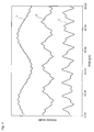
- ion motion in a quadrupole field generated by a time-varying rectangular wave voltage can be defined by applying Newton's equation in different time segments. Within each segment the electric field is constant and so the equation can be easily solved.
- the curves shown in Figure 4 represent ion position as a function of time for motion in the z-direction obtained by numerical calculation based on the above matrix calculus.
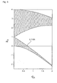
- GB 1346393 and a paper by the same inventor have disclosed the method of choosing band-width of the stability region by varying the duty cycle of the rectangular wave and carrying out mass scanning by scanning the amplitude of the rectangular wave voltage.
- an alternative, more favourable method for mass selective scan does exist.
- This frequency will be referred to as the intrinsic frequency of the ion motion.
- the oscillation at this frequency is caused by the integrated effect of the rectangular wave electric field, and its frequency is a function of mass-to-charge ratio and of the repetition rate of the driving rectangular wave voltage. Therefore, in the present invention an additional dipolar excitation voltage is used to cause ions having a selected mass-to-charge ratio to resonant at the intrinsic frequency ⁇ z .
- these ions can be selectively excited and even ejected from an ion trap so that they can be detected by an external detector.
- the resonant excitation also increases the kinetic energy of the selected ions and may promote certain chemical reactions or induce image current for Fourier transform detection.
- the excitation AC voltage can be a single frequency, sinusoidal voltage or a rectangular wave voltage or a waveform composed of multi-frequency components.
- ⁇ 0 ion motion in the z direction will be resonantly excited.
- the oscillation amplitude of the resonant ions will increase until the ions reach the end-cap electrodes or are ejected through the end-cap holes.
- repetition rate f and the voltages defining the rectangular wave voltage mass scanning using the desired resonance technique can be implemented in a variety of different ways:
- the rectangular wave voltage driven quadrupole mass spectrometry has the following merits compared with the current RF driven quadrupole mass spectrometry.
- the rectangular wave voltage may be generated using a switching circuit which does not employ a LC resonator and so the frequency or the wave repetition rate can be easily changed.
- a practical range may be from 10kHz to 10MHz. It is known from the characteristics of ion motion in the quadrupole electric field that the range of mass scanning is made wider by varying frequency than by varying voltage within certain practical limits (for example discharge at high voltage).
- a rectangular waveform can be defined using more parameters than is the case for a sinusoidal waveform e.g. amplitude, repetition rate, number of transitions within each cycle and their separations. These parameters provide more options for storing and manipulating ions. For example, the rectangular waveform pattern can easily be changed intermittently or temporarily during which time the ions from an external ion source can be introduced into the quadrupole device.
- a switching circuit used to generate a rectangular wave voltage consumes less power than an untuned analogue circuit used to generate an RF drive voltage. This leads to a reduction in the power specification of the associated electronics.
Landscapes
- Chemical & Material Sciences (AREA)
- Analytical Chemistry (AREA)
- Electron Tubes For Measurement (AREA)
- Other Investigation Or Analysis Of Materials By Electrical Means (AREA)
Applications Claiming Priority (3)
| Application Number | Priority Date | Filing Date | Title |
|---|---|---|---|
| GB9924722 | 1999-10-19 | ||
| GBGB9924722.3A GB9924722D0 (en) | 1999-10-19 | 1999-10-19 | Methods and apparatus for driving a quadrupole device |
| PCT/GB2000/003964 WO2001029875A2 (en) | 1999-10-19 | 2000-10-16 | Methods and apparatus for driving a quadrupole ion trap device |
Publications (2)
| Publication Number | Publication Date |
|---|---|
| EP1222680A2 EP1222680A2 (en) | 2002-07-17 |
| EP1222680B1 true EP1222680B1 (en) | 2009-09-30 |
Family
ID=10863000
Family Applications (1)
| Application Number | Title | Priority Date | Filing Date |
|---|---|---|---|
| EP00968112A Expired - Lifetime EP1222680B1 (en) | 1999-10-19 | 2000-10-16 | Methods and apparatus for driving a quadrupole ion trap device |
Country Status (7)
| Country | Link |
|---|---|
| US (1) | US7193207B1 (enExample) |
| EP (1) | EP1222680B1 (enExample) |
| JP (1) | JP4668496B2 (enExample) |
| DE (1) | DE60043067D1 (enExample) |
| GB (1) | GB9924722D0 (enExample) |
| RU (1) | RU2249275C2 (enExample) |
| WO (1) | WO2001029875A2 (enExample) |
Families Citing this family (46)
| Publication number | Priority date | Publication date | Assignee | Title |
|---|---|---|---|---|
| GB0031342D0 (en) | 2000-12-21 | 2001-02-07 | Shimadzu Res Lab Europe Ltd | Method and apparatus for ejecting ions from a quadrupole ion trap |
| GB0121172D0 (en) | 2001-08-31 | 2001-10-24 | Shimadzu Res Lab Europe Ltd | A method for dissociating ions using a quadrupole ion trap device |
| GB2381653A (en) | 2001-11-05 | 2003-05-07 | Shimadzu Res Lab Europe Ltd | A quadrupole ion trap device and methods of operating a quadrupole ion trap device |
| DE10325581B4 (de) | 2003-06-05 | 2008-11-27 | Bruker Daltonik Gmbh | Verfahren und Vorrichtung für das Einspeichern von Ionen in Quadrupol-Ionenfallen |
| GB0312940D0 (en) | 2003-06-05 | 2003-07-09 | Shimadzu Res Lab Europe Ltd | A method for obtaining high accuracy mass spectra using an ion trap mass analyser and a method for determining and/or reducing chemical shift in mass analysis |
| GB0404106D0 (en) | 2004-02-24 | 2004-03-31 | Shimadzu Res Lab Europe Ltd | An ion trap and a method for dissociating ions in an ion trap |
| GB0404285D0 (en) * | 2004-02-26 | 2004-03-31 | Shimadzu Res Lab Europe Ltd | A tandem ion-trap time-of flight mass spectrometer |
| US7034293B2 (en) * | 2004-05-26 | 2006-04-25 | Varian, Inc. | Linear ion trap apparatus and method utilizing an asymmetrical trapping field |
| CN1326191C (zh) | 2004-06-04 | 2007-07-11 | 复旦大学 | 用印刷电路板构建的离子阱质量分析仪 |
| GB2415541B (en) * | 2004-06-21 | 2009-09-23 | Thermo Finnigan Llc | RF power supply for a mass spectrometer |
| US20060118716A1 (en) * | 2004-11-08 | 2006-06-08 | The University Of British Columbia | Ion excitation in a linear ion trap with a substantially quadrupole field having an added hexapole or higher order field |
| JP4806214B2 (ja) * | 2005-01-28 | 2011-11-02 | 株式会社日立ハイテクノロジーズ | 電子捕獲解離反応装置 |
| JP4766549B2 (ja) | 2005-08-29 | 2011-09-07 | 株式会社島津製作所 | レーザー照射質量分析装置 |
| RU2368980C1 (ru) * | 2005-08-30 | 2009-09-27 | Сян ФАН | Ионная ловушка, мультипольная электродная система и электрод для масс-спектрометрического анализа |
| WO2007057623A1 (en) * | 2005-11-16 | 2007-05-24 | Shimadzu Corporation | Mass spectrometer |
| GB0526245D0 (en) * | 2005-12-22 | 2006-02-01 | Shimadzu Res Lab Europe Ltd | A mass spectrometer using a dynamic pressure ion source |
| GB0624679D0 (en) | 2006-12-11 | 2007-01-17 | Shimadzu Corp | A time-of-flight mass spectrometer and a method of analysing ions in a time-of-flight mass spectrometer |
| WO2008072326A1 (ja) * | 2006-12-14 | 2008-06-19 | Shimadzu Corporation | イオントラップ飛行時間型質量分析装置 |
| JP2008282594A (ja) | 2007-05-09 | 2008-11-20 | Shimadzu Corp | イオントラップ型質量分析装置 |
| CN101075546B (zh) * | 2007-05-17 | 2011-01-12 | 上海华质生物技术有限公司 | 离子质量过滤器及过滤方法 |
| US7863562B2 (en) * | 2007-06-22 | 2011-01-04 | Shimadzu Corporation | Method and apparatus for digital differential ion mobility separation |
| GB0712252D0 (en) * | 2007-06-22 | 2007-08-01 | Shimadzu Corp | A multi-reflecting ion optical device |
| JP4941402B2 (ja) * | 2008-05-12 | 2012-05-30 | 株式会社島津製作所 | 質量分析装置 |
| GB0809950D0 (en) * | 2008-05-30 | 2008-07-09 | Thermo Fisher Scient Bremen | Mass spectrometer |
| DE102010018340A1 (de) | 2009-05-26 | 2010-12-02 | Karlsruher Institut für Technologie | Verfahren für eine durchstimmbare Radiofrequenz-Hochspannungsversorgung für Multipol-Ionenspeicher als Nanopartikelführung und -speicher |
| JP5146411B2 (ja) * | 2009-06-22 | 2013-02-20 | 株式会社島津製作所 | イオントラップ質量分析装置 |
| JP5407616B2 (ja) * | 2009-07-14 | 2014-02-05 | 株式会社島津製作所 | イオントラップ装置 |
| US20110139972A1 (en) * | 2009-12-11 | 2011-06-16 | Mark Hardman | Methods and Apparatus for Providing FAIMS Waveforms Using Solid-State Switching Devices |
| JP5440449B2 (ja) * | 2010-08-30 | 2014-03-12 | 株式会社島津製作所 | イオントラップ質量分析装置 |
| JP5533612B2 (ja) | 2010-12-07 | 2014-06-25 | 株式会社島津製作所 | イオントラップ飛行時間型質量分析装置 |
| CN102683153A (zh) * | 2011-03-07 | 2012-09-19 | 北京普析通用仪器有限责任公司 | 质量分析器和具有该质量分析器的质谱仪 |
| CN107658203B (zh) | 2011-05-05 | 2020-04-14 | 岛津研究实验室(欧洲)有限公司 | 操纵带电粒子的装置 |
| JP5712886B2 (ja) * | 2011-09-29 | 2015-05-07 | 株式会社島津製作所 | イオントラップ質量分析装置 |
| US8669520B2 (en) | 2012-07-26 | 2014-03-11 | Hamilton Sundstrand Corporation | Waveform generation for ion trap |
| GB201309282D0 (en) | 2013-05-23 | 2013-07-10 | Shimadzu Corp | Circuit for generating a voltage waveform |
| US9490115B2 (en) | 2014-12-18 | 2016-11-08 | Thermo Finnigan Llc | Varying frequency during a quadrupole scan for improved resolution and mass range |
| US9773655B2 (en) * | 2014-05-21 | 2017-09-26 | Shimadzu Corporation | Radio-frequency voltage generator |
| GB201507474D0 (en) | 2015-04-30 | 2015-06-17 | Shimadzu Corp | A circuit for generating a voltage waveform at an output node |
| RU2613347C2 (ru) * | 2015-07-09 | 2017-03-16 | Федеральное государственное бюджетное образовательное учреждение высшего профессионального образования "Рязанский государственный радиотехнический университет" | Способ развертки спектров масс линейной ионной ловушкой с дипольным возбуждением |
| US11348778B2 (en) | 2015-11-02 | 2022-05-31 | Purdue Research Foundation | Precursor and neutral loss scan in an ion trap |
| US11067538B2 (en) | 2016-04-02 | 2021-07-20 | Dh Technologies Development Pte. Ltd. | Systems and methods for effective gap filtering and atmospheric pressure RF heating of ions |
| GB201615127D0 (en) * | 2016-09-06 | 2016-10-19 | Micromass Ltd | Quadrupole devices |
| GB201615469D0 (en) * | 2016-09-12 | 2016-10-26 | Univ Of Warwick The | Mass spectrometry |
| JP7215589B2 (ja) | 2019-09-27 | 2023-01-31 | 株式会社島津製作所 | イオントラップ質量分析計、質量分析方法および制御プログラム |
| CN112362718B (zh) * | 2020-10-12 | 2024-07-02 | 深圳市卓睿通信技术有限公司 | 一种拓宽质谱仪检测质量范围的方法及装置 |
| CN112491416B (zh) * | 2020-11-27 | 2024-03-15 | 西安空间无线电技术研究所 | 一种用于离子微波频标的离子阱射频势实时监测反馈系统 |
Citations (1)
| Publication number | Priority date | Publication date | Assignee | Title |
|---|---|---|---|---|
| GB1346393A (en) * | 1971-03-08 | 1974-02-06 | Unisearch Ltd | Means for effecting improvements to mass spectrometers and mass filters |
Family Cites Families (20)
| Publication number | Priority date | Publication date | Assignee | Title |
|---|---|---|---|---|
| IT528250A (enExample) | 1953-12-24 | |||
| US3197633A (en) | 1962-12-04 | 1965-07-27 | Siemens Ag | Method and apparatus for separating ions of respectively different specific electric charges |
| SU1088090A1 (ru) | 1979-03-11 | 1984-04-23 | Рязанский Радиотехнический Институт | Способ питани датчиков квадрупольных масс-спектрометров |
| US4540884A (en) | 1982-12-29 | 1985-09-10 | Finnigan Corporation | Method of mass analyzing a sample by use of a quadrupole ion trap |
| EP0202943B2 (en) | 1985-05-24 | 2004-11-24 | Thermo Finnigan LLC | Method of operating an ion trap |
| US4761545A (en) | 1986-05-23 | 1988-08-02 | The Ohio State University Research Foundation | Tailored excitation for trapped ion mass spectrometry |
| US4755670A (en) * | 1986-10-01 | 1988-07-05 | Finnigan Corporation | Fourtier transform quadrupole mass spectrometer and method |
| US5206506A (en) | 1991-02-12 | 1993-04-27 | Kirchner Nicholas J | Ion processing: control and analysis |
| US5134286A (en) | 1991-02-28 | 1992-07-28 | Teledyne Cme | Mass spectrometry method using notch filter |
| US5381007A (en) * | 1991-02-28 | 1995-01-10 | Teledyne Mec A Division Of Teledyne Industries, Inc. | Mass spectrometry method with two applied trapping fields having same spatial form |
| RU2010392C1 (ru) * | 1991-05-08 | 1994-03-30 | Эрнст Пантелеймонович Шеретов | Способ питания анализатора гиперболоидного масс-спектрометра и гиперболоидный масс-спектрометр |
| RU2019887C1 (ru) * | 1992-02-04 | 1994-09-15 | Шеретов Эрнст Пантелеймонович | Способ масс-спектрометрического анализа в гиперболоидном масс-спектрометре типа ионной ловушки |
| US5629186A (en) | 1994-04-28 | 1997-05-13 | Lockheed Martin Corporation | Porous matrix and method of its production |
| RU2068599C1 (ru) * | 1994-06-22 | 1996-10-27 | Эрнст Пантелеймонович Шеретов | Способ питания анализатора гиперболоидного масс-спектрометра |
| JP3269313B2 (ja) * | 1995-02-14 | 2002-03-25 | 株式会社日立製作所 | 質量分析装置及び質量分析方法 |
| JPH095298A (ja) * | 1995-06-06 | 1997-01-10 | Varian Assoc Inc | 四重極イオントラップ内の選択イオン種を検出する方法 |
| US5714755A (en) * | 1996-03-01 | 1998-02-03 | Varian Associates, Inc. | Mass scanning method using an ion trap mass spectrometer |
| US5625186A (en) | 1996-03-21 | 1997-04-29 | Purdue Research Foundation | Non-destructive ion trap mass spectrometer and method |
| DE69806415T2 (de) * | 1997-12-05 | 2003-02-20 | The University Of British Columbia, Vancouver | Verfahren zur untersuchung von ionen in einem apparat mit einem flugzeit-spektrometer und einer linearen quadrupol-ionenfalle |
| GB0031342D0 (en) * | 2000-12-21 | 2001-02-07 | Shimadzu Res Lab Europe Ltd | Method and apparatus for ejecting ions from a quadrupole ion trap |
-
1999
- 1999-10-19 GB GBGB9924722.3A patent/GB9924722D0/en not_active Ceased
-
2000
- 2000-10-16 EP EP00968112A patent/EP1222680B1/en not_active Expired - Lifetime
- 2000-10-16 DE DE60043067T patent/DE60043067D1/de not_active Expired - Lifetime
- 2000-10-16 RU RU2002113091/28A patent/RU2249275C2/ru not_active IP Right Cessation
- 2000-10-16 US US10/089,963 patent/US7193207B1/en not_active Expired - Lifetime
- 2000-10-16 JP JP2001531124A patent/JP4668496B2/ja not_active Expired - Fee Related
- 2000-10-16 WO PCT/GB2000/003964 patent/WO2001029875A2/en not_active Ceased
Patent Citations (1)
| Publication number | Priority date | Publication date | Assignee | Title |
|---|---|---|---|---|
| GB1346393A (en) * | 1971-03-08 | 1974-02-06 | Unisearch Ltd | Means for effecting improvements to mass spectrometers and mass filters |
Also Published As
| Publication number | Publication date |
|---|---|
| GB9924722D0 (en) | 1999-12-22 |
| WO2001029875A3 (en) | 2002-05-02 |
| RU2249275C2 (ru) | 2005-03-27 |
| WO2001029875A2 (en) | 2001-04-26 |
| RU2002113091A (ru) | 2004-01-27 |
| EP1222680A2 (en) | 2002-07-17 |
| DE60043067D1 (de) | 2009-11-12 |
| JP4668496B2 (ja) | 2011-04-13 |
| JP2003512702A (ja) | 2003-04-02 |
| US7193207B1 (en) | 2007-03-20 |
Similar Documents
| Publication | Publication Date | Title |
|---|---|---|
| EP1222680B1 (en) | Methods and apparatus for driving a quadrupole ion trap device | |
| CN101048845B (zh) | 用于质谱法在四极离子阱中分离离子 | |
| US10366872B2 (en) | Frequency and amplitude scanned quadrupole mass filter and methods | |
| CN103367094B (zh) | 离子阱分析器以及离子阱质谱分析方法 | |
| Ding et al. | A digital ion trap mass spectrometer coupled with atmospheric pressure ion sources | |
| EP2681759B1 (en) | Mass analyser and method of mass analysis | |
| US7285773B2 (en) | Quadrupole ion trap device and methods of operating a quadrupole ion trap device | |
| US6649911B2 (en) | Method of selecting ions in an ion storage device | |
| US6900433B2 (en) | Method and apparatus for ejecting ions from a quadrupole ion trap | |
| JP5440449B2 (ja) | イオントラップ質量分析装置 | |
| WO1997002591A1 (en) | Mass spectrometer | |
| US7495211B2 (en) | Measuring methods for ion cyclotron resonance mass spectrometers | |
| US5623144A (en) | Mass spectrometer ring-shaped electrode having high ion selection efficiency and mass spectrometry method thereby | |
| Ding et al. | Ion motion in the rectangular wave quadrupole field and digital operation mode of a quadrupole ion trap mass spectrometer | |
| Hilger et al. | Square wave modulation of a mirror lens for ion isolation in a Fourier transform electrostatic linear ion trap mass spectrometer | |
| JP4506260B2 (ja) | イオン蓄積装置におけるイオン選別の方法 | |
| CN114616647A (zh) | 傅立叶变换质谱法的方法和系统 | |
| JP3960306B2 (ja) | イオントラップ装置 | |
| EP1696467B1 (en) | Apparatus and method for lowering the ion fragmentation cut-off limit | |
| JP5293562B2 (ja) | イオントラップ質量分析装置 |
Legal Events
| Date | Code | Title | Description |
|---|---|---|---|
| PUAI | Public reference made under article 153(3) epc to a published international application that has entered the european phase |
Free format text: ORIGINAL CODE: 0009012 |
|
| 17P | Request for examination filed |
Effective date: 20020325 |
|
| AK | Designated contracting states |
Kind code of ref document: A2 Designated state(s): AT BE CH CY DE DK ES FI FR GB GR IE IT LI LU MC NL PT SE |
|
| RBV | Designated contracting states (corrected) |
Designated state(s): DE GB |
|
| 17Q | First examination report despatched |
Effective date: 20090130 |
|
| GRAP | Despatch of communication of intention to grant a patent |
Free format text: ORIGINAL CODE: EPIDOSNIGR1 |
|
| GRAS | Grant fee paid |
Free format text: ORIGINAL CODE: EPIDOSNIGR3 |
|
| GRAA | (expected) grant |
Free format text: ORIGINAL CODE: 0009210 |
|
| AK | Designated contracting states |
Kind code of ref document: B1 Designated state(s): DE GB |
|
| REG | Reference to a national code |
Ref country code: GB Ref legal event code: FG4D |
|
| REF | Corresponds to: |
Ref document number: 60043067 Country of ref document: DE Date of ref document: 20091112 Kind code of ref document: P |
|
| PLBE | No opposition filed within time limit |
Free format text: ORIGINAL CODE: 0009261 |
|
| STAA | Information on the status of an ep patent application or granted ep patent |
Free format text: STATUS: NO OPPOSITION FILED WITHIN TIME LIMIT |
|
| 26N | No opposition filed |
Effective date: 20100701 |
|
| PGFP | Annual fee paid to national office [announced via postgrant information from national office to epo] |
Ref country code: GB Payment date: 20161020 Year of fee payment: 17 Ref country code: DE Payment date: 20161026 Year of fee payment: 17 |
|
| REG | Reference to a national code |
Ref country code: DE Ref legal event code: R119 Ref document number: 60043067 Country of ref document: DE |
|
| GBPC | Gb: european patent ceased through non-payment of renewal fee |
Effective date: 20171016 |
|
| PG25 | Lapsed in a contracting state [announced via postgrant information from national office to epo] |
Ref country code: DE Free format text: LAPSE BECAUSE OF NON-PAYMENT OF DUE FEES Effective date: 20180501 Ref country code: GB Free format text: LAPSE BECAUSE OF NON-PAYMENT OF DUE FEES Effective date: 20171016 |