EP1222636B1 - Reconstitution statistique de surfaces en trois dimensions - Google Patents
Reconstitution statistique de surfaces en trois dimensions Download PDFInfo
- Publication number
- EP1222636B1 EP1222636B1 EP00962642A EP00962642A EP1222636B1 EP 1222636 B1 EP1222636 B1 EP 1222636B1 EP 00962642 A EP00962642 A EP 00962642A EP 00962642 A EP00962642 A EP 00962642A EP 1222636 B1 EP1222636 B1 EP 1222636B1
- Authority
- EP
- European Patent Office
- Prior art keywords
- model
- contours
- dimensional
- image
- dimensions
- Prior art date
- Legal status (The legal status is an assumption and is not a legal conclusion. Google has not performed a legal analysis and makes no representation as to the accuracy of the status listed.)
- Expired - Lifetime
Links
Images


Classifications
-
- A—HUMAN NECESSITIES
- A61—MEDICAL OR VETERINARY SCIENCE; HYGIENE
- A61B—DIAGNOSIS; SURGERY; IDENTIFICATION
- A61B90/00—Instruments, implements or accessories specially adapted for surgery or diagnosis and not covered by any of the groups A61B1/00 - A61B50/00, e.g. for luxation treatment or for protecting wound edges
- A61B90/36—Image-producing devices or illumination devices not otherwise provided for
-
- A—HUMAN NECESSITIES
- A61—MEDICAL OR VETERINARY SCIENCE; HYGIENE
- A61B—DIAGNOSIS; SURGERY; IDENTIFICATION
- A61B34/00—Computer-aided surgery; Manipulators or robots specially adapted for use in surgery
- A61B34/20—Surgical navigation systems; Devices for tracking or guiding surgical instruments, e.g. for frameless stereotaxis
-
- A—HUMAN NECESSITIES
- A61—MEDICAL OR VETERINARY SCIENCE; HYGIENE
- A61B—DIAGNOSIS; SURGERY; IDENTIFICATION
- A61B34/00—Computer-aided surgery; Manipulators or robots specially adapted for use in surgery
- A61B34/10—Computer-aided planning, simulation or modelling of surgical operations
- A61B2034/101—Computer-aided simulation of surgical operations
- A61B2034/105—Modelling of the patient, e.g. for ligaments or bones
-
- A—HUMAN NECESSITIES
- A61—MEDICAL OR VETERINARY SCIENCE; HYGIENE
- A61B—DIAGNOSIS; SURGERY; IDENTIFICATION
- A61B34/00—Computer-aided surgery; Manipulators or robots specially adapted for use in surgery
- A61B34/20—Surgical navigation systems; Devices for tracking or guiding surgical instruments, e.g. for frameless stereotaxis
- A61B2034/2046—Tracking techniques
- A61B2034/2055—Optical tracking systems
-
- A—HUMAN NECESSITIES
- A61—MEDICAL OR VETERINARY SCIENCE; HYGIENE
- A61B—DIAGNOSIS; SURGERY; IDENTIFICATION
- A61B34/00—Computer-aided surgery; Manipulators or robots specially adapted for use in surgery
- A61B34/20—Surgical navigation systems; Devices for tracking or guiding surgical instruments, e.g. for frameless stereotaxis
- A61B2034/2072—Reference field transducer attached to an instrument or patient
-
- A—HUMAN NECESSITIES
- A61—MEDICAL OR VETERINARY SCIENCE; HYGIENE
- A61B—DIAGNOSIS; SURGERY; IDENTIFICATION
- A61B34/00—Computer-aided surgery; Manipulators or robots specially adapted for use in surgery
- A61B34/25—User interfaces for surgical systems
- A61B2034/256—User interfaces for surgical systems having a database of accessory information, e.g. including context sensitive help or scientific articles
-
- A—HUMAN NECESSITIES
- A61—MEDICAL OR VETERINARY SCIENCE; HYGIENE
- A61B—DIAGNOSIS; SURGERY; IDENTIFICATION
- A61B90/00—Instruments, implements or accessories specially adapted for surgery or diagnosis and not covered by any of the groups A61B1/00 - A61B50/00, e.g. for luxation treatment or for protecting wound edges
- A61B90/36—Image-producing devices or illumination devices not otherwise provided for
- A61B2090/364—Correlation of different images or relation of image positions in respect to the body
- A61B2090/367—Correlation of different images or relation of image positions in respect to the body creating a 3D dataset from 2D images using position information
Definitions
- the present invention relates to the reconstruction of images in three dimensions and, more particularly, the reconstruction surface contours of an image from views, even incomplete, in two dimensions.
- An example of application of the present invention is the reconstruction of images representing bone elements to from two-dimensional images taken, for example, from X-rays. Such images can be used, for example, to simulate a surgical intervention allowing the practitioner to preview the respective positions of the bones at a joint, for example, in case of ligament plasty or in place of prosthesis.
- the scanner technique gives good results but is a heavy and expensive implementation. Indeed, the use of a scanner makes it possible to obtain a set of images in two dimensions not only providing information on the contour but also on the inside of the bone. Now in many applications, only knowledge of the outline area of the bone or object is required.
- Another example of application of the present invention is the reconstruction of incomplete bones, for example, in archeology.
- a reconstruction of three-dimensional images can allow to find in a near perfect form original bone even if it is discovered so incomplete.
- similar problems to those exposed above in relation to the simulation of interventions arise.
- the present invention applies more particularly the reconstruction of images relating to identified objects, that is to say, which we know in advance the general form. For example, for a bone, you must first decide to what bone it is.
- the present invention aims to propose a new process of three-dimensional image reconstruction which overcomes the disadvantages of known techniques.
- the invention aims, in particular, to offer a solution that does not require employment expensive of an x-ray scanner.
- the present invention also aims to provide a solution that is compatible with minimal exposure to X-rays or equivalent.
- the invention further aims to minimize the number of views in two dimensions necessary to reconstruct the image in three dimensions.
- the model is obtained from a population of objects for which one searches for the statistical correspondence common to all objects to determine a mean shape and deformations main compared to this average shape, so have at least one statistical model.
- the iterative selection steps consist in subjecting the statistical model, successively, a rigid transformation modifying its position and / or its orientation and a deformation non-rigid modifying its surface contours.
- two-dimensional image contours are obtained automatically by projecting the model in the image plane in two dimensions, and by deforming the projected contours so as to to coincide with the points of strong gradient in levels of gray of the two-dimensional image.
- automatic determination of the contours of the image in two dimensions is performed iteratively, each iteration being inserted between two successive iterations of the stages of selection.
- coordinates are determined in the reference frame of reference in three-dimensional points of the object, so as to have additional benchmarks for selection steps iterative of position, orientation, and deformation.
- the number of images used depends on the desired precision.
- the surface of the model is made up of triangle elements, said elements deviations being measured with respect to points of certain edges constituting generators of the three-dimensional contour.
- the process is applied to the reconstruction of the surface contours of several objects linked together by relations of rigid and / or elastic transformation.
- the method is applied to the reconstruction of bone images.
- the invention also relates to a processing system. of images, comprising means for implementing the method three-dimensional image reconstruction.
- a feature of the present invention is find the position and orientation of an object to be reconstructed, and which we know at least a two-dimensional view, from a database containing models of this object. When multiple two-dimensional views are used, these views are all referenced in the same repository. So the invention concerns the reconstruction of an image representing an object already identified and of which we can have size models and / or of different shape.
- a feature of a preferred embodiment of the present invention is to use at least one statistical model deformable, established from the database, for reconstruct the three-dimensional shape of the object. So, the invention provides for defining, before any reconstitution, a database containing three-dimensional models of the object to be reconstructed or, preferably, one or more models deformable statistics from this database.
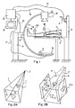
- Figure 1 shows a schematic view of a system of three-dimensional image reconstruction according to a mode of realization of the present invention.
- the example of figure 1 concerns the reconstruction of the image of a bone 1 from two-dimensional x-rays.
- Figure 1 there is shown schematically and partially the body of a patient p whose leg contains the bone 1 that one wishes to visualize.
- the leg of the patient p (therefore bone 1) is, for example, placed on a table 2.
- a bracket 3 carries a location device 4 in three dimensions which can be optical, magnetic, mechanical or ultrasonic and which locates the position and orientation of multiple sensor-emitters consisting, for example, of infrared diodes, reflectors, magnetic transmitters, ultrasonic, etc.
- sensor-transmitters can be attached to the radiology system, close to source 7 (sensor-emitter 19) or close to an image detector 9 (sensor-transmitter 5), to identify the position of the radiology system in relation to to the reference frame of the sensor-transmitter 18.
- the sensor-transmitters 5 and 19 are difficult to spot due to their remoteness or the presence of parasitic objects in the measuring range of the locator 4.
- a sensor-transmitter 20 can be installed on table 2 in the measurement field of the locator 4. On then positions the radiological system in good conditions the positions of the sensor-transmitters 5 and 19 with respect to the sensor-transmitter 20 once and for all (we only repeat this step if we move the system radiology as a whole).
- the radiological system being equipped with angular encoders on its axes, as will be detailed below, the changes in relative position of the radiological system are measured using these encoders and can therefore be carried over in the repository of the sensor-transmitter 20.
- all radiographs are calibrated in the repository of the sensor-transmitter 18 which can be mobile.
- the device 6 is, for example, made up of a x-ray source 7 carried by a first end of an arm 8 in a semicircle, the other end of which is intended to receive the x-ray printing film 9, or an electronic sensor equivalent such as an image intensifier, or a detector dish with amorphous silicon.
- the relationship between arm 8 and the table 2 is such that it is between source 7 and the sensor 9.
- the arm 8 is mounted to rotate about an axis 10, motorized or manual displacement, and carried by a bracket 11.
- the two-dimensional shooting set can thus rotate around bone 1 to make the desired number of x-rays of it.
- the optical locator 4 can be associated with an angular coding device for the axis position 10.
- a computer 12 preferably associated with a screen visualization 13.
- FIG. 1 we have symbolized by connections single lines 14, 15, 16 and 17, the computer exchange buses electrical control and data signals between the computer 12 and, respectively, the locator 4, the source 7, the engine or the optional axis 10 encoder and sensor 9.
- FIGS. 2A and 2B illustrate two modes of taking views according to two embodiments of the present invention.
- the two-dimensional views have been shown by the respective plans in which they are taken, that is to say by the shape of the surface of the sensor 9 (FIG. 1) when taken. This corresponds to the radiographic images in two dimensions retrieved by the computer system.
- FIG. 2A represents the case of a single shot in a plane P1, providing an image Il of bone 1.
- the position from source 7 has been symbolized by a point where back projection radii of the four corners of the plane P1.
- FIG. 2B represents the case of a triple take of views in planes P1, P2 and P3, providing three images I1, I2 and I3 in two dimensions of bone 1.
- the position of the source is not constant, it is different for each shooting.
- all source positions are known in the reference frame.
- only the radii r1 of the four corners of the plane P1 in the position of the image I1 have been represented.
- the source of shots may be subject to, between two two-dimensional images, other movements than in the same plane as illustrated by FIGS. 1 and 2B.
- the arm 8 of the shooting system 6 can have more than two degrees of freedom, each of which can have an angular coding device.
- the arm 8 is mounted on two axes of rotation horizontal and vertical and a vertical translation axis.
- two-dimensional images may be only partial.
- these can be interpreted by the operator to validate the contours of two-dimensional views to be taken into account for the reconstruction. Such a interpretation is not troublesome due to the low number of two-dimensional views required according to the invention (less than ten in general).
- Validation of contours in the system IT can be done, for example, by means of a mouse, optical pencil, touch screen, or equivalent, conventionally for a contour recording on a grayscale image.
- the determining contours on radiographic images is automated by implementing a so-called resetting process in two dimensions.
- One such method is to determine the outline automatically by analyzing the strongest gradients in shades of grey. This process is described, for example, in the Gelu Ionescu's thesis, presented publicly on December 4, 1998 at the Joseph Fourier University in Grenoble (France), and having for title "Segmentation and registration of ultrasound images by use of physiological and morphological knowledge ".
- this registration process is implemented in two dimensions in combination with a projection, on the image in two dimensions, from the deformable statistical model of the object whose surface contours we want to reconstruct in three dimensions.
- the view or views in two dimensions have been obtained, it remains to be determined by research match in database, shape and size of the object (here, the bone) in three dimensions.
- the invention provides for finding the model for which the distances between the contours of each two-dimensional view and the surface of the model are minimal.
- a method of determining a statistical model to from a family of samples is described, for example, in the article "Building a Complete Surface Model from Sparse Data Using Statistical Shape Models: Application to Computer Assisted Knee Surgery "by Markus Fleute and Stéphane Lavhui, published in MEDICAL IMAGE COMPUTING AND COMPUTER-ASSISTED INTERVENTION - MICCAI'98, Springer-Verlag LNCS Series, pages 880-887, in October 1998, the content of which is incorporated here by reference. Note that the precision of the reconstruction of the surface contours operated by the invention depends on the samples used to build the database of the statistical model.
- a statistical model of femur is created from a population of samples having normal forms (without pathology)
- the statistical model is created from a large population of samples containing both forms normal and pathological forms, we can reconstruct, with precision, normal and pathological objects.
- the model is subjected to a non-rigid deformation, that is to say that without changing its orientation, we change its shape from data contained in the statistical base by modifying the coefficients of the main modes of the model, until obtaining the shape whose contours are closest to the rays of OHP.
- the model is prepositioned with very roughly by the operator compared to the views in two dimensions displayed on the screen. Note that the means (computer) image processing used are conventional in their structure and therefore do not need to be detailed.
- FIG. 3A represents a view in three dimensions of a model 21 before any deformation. It is, by example, of a statistical model of the invention positioned by the practitioner in an approximate orientation.
- Figure 3B shows the model 21 'of FIG. 3A at the end of the orientation step without modification of form.
- Figure 3C shows image 22 in three dimensions resulting from the implementation of the invention, that is to say corresponding to the 21 'model, deformed so that the rear projection radii are (ideally) tangent to all its contours.
- the transformation is "rigid", that is to say that the model is not deformed.
- the model 21 undergoes translations and rotations in order to obtain minimum difference measurements between each rear projection ray starting from the contour points of the image and the surface of the object in its current position.
- FIG. 3B in which the model 21 'has a position and correct orientation but still an imperfect shape. It is why certain rays r 'are not tangent but pass through the model.
- the position resulting from the transformation rigid is obtained by a method (algorithm) called the nearest point (Iterative Closest Point, ICP).
- algorithm algorithm
- ICP Intelligent Closest Point
- the transformation is "non-rigid" (elastic) and consists in deforming the 21 'model without changing its orientation until obtaining image 22 in three dimensions for which all the rear projection radii r " are at a minimum distance from the contours (ideally tangent).
- This non-rigid transformation is carried out, for example and according to a first embodiment, by calculating the parameters deformation from an algorithm known under the name Anglo-Saxon "Down Hill Simplex". This algorithm was described, for example, in 1965 by J.A. Nelder and R. Mead in COMPUTER JOURNAL, vol. 7, pages 308-313, the content of which is incorporated here by reference.
- the algorithm used to determine the non-rigid transformation of the statistical model is based on the Levenberg-Marquardt method.
- the principle of this method is to determine the minimum of a multidimensional non-linear function using the partial derivatives of the function with respect to the parameters deformation of the model.
- This method has been described, by example, in 1963 by D.W. Marquardt in JOURNAL OF THE SOCIETY FOR INDUSTRIAL AND APPLIED MATHEMATICS, vol. 11, pages 431-441, the content of which is incorporated herein by reference.
- the function of which we are looking for the minimum is here the sum of the squares of the distances between a set of rear projection rays based on the contour points and the surface of the model.
- the parameters of the search for the minimum are the coefficients that we apply to each mode of distortion of the statistical model, as well as this is presented in the article "Building a Complete Surface Model from Sparse Data Using Statistical Shape Models: Application to Computer Assisted Knee Surgery "by Markus Fleute and Stéphane Lavowing, already cited.
- the minimum deviation assessments are not necessarily comprehensively for all elements of surface of the model. Indeed, this would sometimes lead to calculations too expensive even if the number of surface elements can be minimized by using triangular elements.
- the deviation assessments are made by with respect to characteristic lines constituting contour generators of the model. This minimizes the number of measuring points. For example, a femur type bone, defined by about 5000 edges of triangular surfaces, is defined by around 300 contour generators.
- the analysis carried out by the method of the invention only affects image contour generators in three dimensions.
- the area of the statistical model is, preferably formed of triangular elements, some of which edges define generators of the contour.
- a generator contour is defined by the edges (edges) of the triangles which, projected on a plane, define the outline (internal or external).
- contour generators considerably reduces (for example, by at least a factor of 10) the number of points to look for in the model to check the match with the reconstructed image.
- Figure 4 illustrates the definition of a outline of a three-dimensional image (model) including the surface is formed of triangular surface elements as described, for example, in the article "Anatomy-based registration of ct-scan and intraoperative x-ray images for guiding a surgical robot "by A. Gueziec, published in IEEE TRANSACTIONS ON MEDICAL IMAGING, 17 (5), pages 715-728, in October 1998, and whose content is incorporated here by reference.
- Figure 4 shows, in a simplified way, two triangles 30 and 31 defining a surface portion of a model in three dimensions and whose common edge constitutes a generator 32 of the outline.
- the calculation to be carried out to determine whether a edge constitutes or not a generator of the contour consists in calculating the respective angles ⁇ and ⁇ between the normals to the surfaces triangles 30 and 31 and rays 33 and 34 connecting the center of these surfaces at the center of projection 35 corresponding to the position of the X-ray source. If one of the angles is less than 90 ° while the other is greater than 90 °, their common edge 32 is then a generator of the contour.
- Figure 5 illustrates the type of measurement performed for determine the difference e between a rear projection radius r and a point of a contour generator.
- This figure represents, of schematically, an image I of the object in a plane P and a form 21 of the statistical model placed on the path of the rays of rear projection of image I to the source (not shown).
- An advantage of the present invention is that it allows a much faster reconstruction of an image in three dimensions compared to known techniques.
- Another advantage of the present invention is that it allows correct alignment of the model even in areas where does not have image projection data in two dimensions (for example, some internal curvatures).
- the surface contour may, if if necessary, be refined by means of a mechanical, optical or magnetic providing spatial coordinates in the same repository as two-dimensional images. We then obtain additional points that can be used in the three-dimensional image search.
- the use of a probe can be used, for example, to reduce the number of views in half dimensions required by giving three-dimensional information.
- the method of the invention can apply to several three-dimensional surface contours constituting one or more objects.
- the model sought must, in the latter case, contain the rigid transformations between each surface contour in three dimensions. In other cases of application to several objects, it is of course necessary to know the different statistical models and possible transformations rigid or elastic between them.
- the present invention is capable of various variants and modifications which will appear to the man of art.
- the number of two-dimensional views to be used for reconstruction depends on accuracy desired and complexity of the model. In some cases, a only a two-dimensional view may suffice.
- the invention has been described in relation to a ray source X mobile, it can be replaced by several sources fixed, provided that the constraint of obtaining images in two dimensions in the same repository.
- the implementation work of the invention of course calls upon techniques of digital image processing whose practical realization is the scope of the person skilled in the art from functional indications given above and in the publications cited in references.
Description
- sélectionner une orientation et une position du modèle dans le référentiel de référence, puis
- sélectionner une déformation du modèle pour modifier ses contours en trois dimensions.
Claims (10)
- Procédé de reconstitution d'une image en trois dimensions représentant les contours surfaciques d'au moins un objet (1), à partir d'au moins une vue en deux dimensions de cet objet prise aux rayons X, caractérisé en ce qu'il consiste à :de façon itérative jusqu'à ce que les contours du modèle soient tels que les écarts, entre des rayons de rétroprojection des contours de l'image en deux dimensions depuis la source et la surface du modèle, soient minimaux, pour obtenir une correspondance entre le modèle et l'image :déterminer la position de la source (7) de prise de vues dans un référentiel de référence ;sélectionner au moins un modèle statistique définissant une forme moyenne de l'objet et ses déformations principales par rapport à cette forme moyenne, le modèle statistique étant calculé à partir d'une population d'objets de même type pour laquelle on recherche la correspondance statistique commune à tous les objets ; etsélectionner une orientation et une position du modèle dans le référentiel de référence en faisant subir au modèle statistique une transformation rigide modifiant sa position et/ou son orientation, puissélectionner une déformation du modèle en faisant subir au modèle statistique une déformation non rigide modifiant ses contours surfaciques.
- Procédé selon la revendication 1, caractérisé en ce que les contours de l'image en deux dimensions sont obtenus automatiquement en projetant le modèle dans le plan de l'image en deux dimensions, et en déformant les contours projetés de façon à les faire coïncider avec les points de fort gradient en niveaux de gris de l'image en deux dimensions.
- Procédé selon la revendication 2, caractérisé en ce que la détermination automatique des contours de l'image en deux dimensions est effectuée de façon itérative, chaque itération étant intercalée entre deux itérations successives des étapes de sélection.
- Procédé selon l'une quelconque des revendications 1 à 3, caractérisé en ce qu'il consiste à déterminer, dans le référentiel de référence, des coordonnées en trois dimensions de points de l'objet, de façon à disposer de points de référence supplémentaires pour les étapes de sélection itératives de position, orientation, et déformation.
- Procédé selon l'une quelconque des revendications 1 à 4, caractérisé en ce qu'il consiste à utiliser plusieurs images en deux dimensions pour lesquelles les positions respectives de la source de prise de vues sont toutes déterminées dans le référentiel de référence, et à effectuer les étapes de sélections itératives en tenant compte des rayons de rétroprojection des contours de toutes les images en deux dimensions.
- Procédé selon la revendication 5, caractérisé en ce que le nombre d'images utilisé est fonction de la précision souhaitée.
- Procédé selon l'une quelconque des revendications 1 à 6, caractérisé en ce que la surface du modèle est constituée d'éléments de triangle, lesdits écarts étant mesurés par rapport à des points de certaines arêtes constituant des générateurs du contour en trois dimensions.
- Procédé selon l'une quelconque des revendications 1 à 7, caractérisé en ce qu'il est appliqué à la reconstitution des contours surfaciques de plusieurs objets liés entre eux par des relations de transformation rigide et/ou élastique.
- Procédé selon l'une quelconque des revendications 1 à 8, caractérisé en ce qu'il est appliqué à la reconstitution d'images d'os.
- Système de traitement d'images, caractérisé en ce qu'il comporte des moyens pour la mise en oeuvre du procédé selon l'une quelconque des revendications 1 à 9.
Applications Claiming Priority (3)
| Application Number | Priority Date | Filing Date | Title |
|---|---|---|---|
| FR9911848 | 1999-09-17 | ||
| FR9911848A FR2798760B1 (fr) | 1999-09-17 | 1999-09-17 | Reconstitution de surfaces en trois dimensions par utilisation de modeles statistiques |
| PCT/FR2000/002546 WO2001022368A1 (fr) | 1999-09-17 | 2000-09-14 | Reconstitution statistique de surfaces en trois dimensions |
Publications (2)
| Publication Number | Publication Date |
|---|---|
| EP1222636A1 EP1222636A1 (fr) | 2002-07-17 |
| EP1222636B1 true EP1222636B1 (fr) | 2004-03-17 |
Family
ID=9550130
Family Applications (1)
| Application Number | Title | Priority Date | Filing Date |
|---|---|---|---|
| EP00962642A Expired - Lifetime EP1222636B1 (fr) | 1999-09-17 | 2000-09-14 | Reconstitution statistique de surfaces en trois dimensions |
Country Status (5)
| Country | Link |
|---|---|
| US (1) | US7227981B1 (fr) |
| EP (1) | EP1222636B1 (fr) |
| DE (1) | DE60009113T2 (fr) |
| FR (1) | FR2798760B1 (fr) |
| WO (1) | WO2001022368A1 (fr) |
Families Citing this family (36)
| Publication number | Priority date | Publication date | Assignee | Title |
|---|---|---|---|---|
| FR2816200A1 (fr) | 2000-11-06 | 2002-05-10 | Praxim | Determination de la position d'une prothese du genou |
| ATE357190T1 (de) | 2002-03-27 | 2007-04-15 | Brainlab Ag | Medizinische navigation bzw. prä-operative behandlungsplanung mit unterstützung durch generische patientendaten |
| US7787932B2 (en) | 2002-04-26 | 2010-08-31 | Brainlab Ag | Planning and navigation assistance using two-dimensionally adapted generic and detected patient data |
| FR2841118B1 (fr) | 2002-06-20 | 2012-03-23 | Perception Raisonnement Action En Medecine | Determination de la position d'un appareil de radiographie ou de radioscopie |
| FR2856170B1 (fr) | 2003-06-10 | 2005-08-26 | Biospace Instr | Procede d'imagerie radiographique pour la reconstruction tridimensionnelle, dispositif et programme d'ordinateur pour mettre en oeuvre ce procede |
| US7873403B2 (en) | 2003-07-15 | 2011-01-18 | Brainlab Ag | Method and device for determining a three-dimensional form of a body from two-dimensional projection images |
| EP1498851A1 (fr) * | 2003-07-15 | 2005-01-19 | BrainLAB AG | Détermination d'une forme tridimensionnelle d'un corps, en particulier d'une structure anatomique, à partir d'images de projection bidimensionnelles |
| WO2005086062A2 (fr) * | 2004-03-05 | 2005-09-15 | Depuy International Limited | Procede et dispositif de reperage |
| SE528068C2 (sv) | 2004-08-19 | 2006-08-22 | Jan Erik Solem Med Jsolutions | Igenkänning av 3D föremål |
| FR2880791B1 (fr) * | 2005-01-18 | 2007-04-06 | Perception Raisonnement Action | Procede et dispositif d'assistance par ordinateur pour la reduction d'une fracture |
| US8463004B2 (en) | 2005-02-18 | 2013-06-11 | Brainlab Ag | Determining shaft and femur neck axes and three-dimensional reconstruction |
| GB0504172D0 (en) * | 2005-03-01 | 2005-04-06 | King S College London | Surgical planning |
| EP1861821A2 (fr) * | 2005-03-24 | 2007-12-05 | Image Metrics Limited | Procede et systeme de caracterisation de la morphologie d'une articulation du genou |
| US8862200B2 (en) | 2005-12-30 | 2014-10-14 | DePuy Synthes Products, LLC | Method for determining a position of a magnetic source |
| US7525309B2 (en) | 2005-12-30 | 2009-04-28 | Depuy Products, Inc. | Magnetic sensor array |
| US7949386B2 (en) | 2006-03-21 | 2011-05-24 | A2 Surgical | Computer-aided osteoplasty surgery system |
| EP1868157A1 (fr) * | 2006-06-14 | 2007-12-19 | BrainLAB AG | Reconstruction des formes en utilisant des images Rayon-X |
| US8214016B2 (en) | 2006-12-12 | 2012-07-03 | Perception Raisonnement Action En Medecine | System and method for determining an optimal type and position of an implant |
| US8068648B2 (en) | 2006-12-21 | 2011-11-29 | Depuy Products, Inc. | Method and system for registering a bone of a patient with a computer assisted orthopaedic surgery system |
| EP2126841A2 (fr) * | 2007-01-16 | 2009-12-02 | Optasia Medical, Limited | Systèmes et procédés de traitement d'images |
| US8660329B2 (en) * | 2007-05-25 | 2014-02-25 | Ecole Nationale Superieure D'arts Et Metiers (Ensam) | Method for reconstruction of a three-dimensional model of a body structure |
| EP2194836B1 (fr) * | 2007-09-25 | 2015-11-04 | Perception Raisonnement Action En Medecine | Appareil pour aider au diagnostic de l'état du cartilage et procédés thérapeutiques |
| EP2083390B1 (fr) | 2008-01-24 | 2016-06-01 | Brainlab AG | Procédé destiné à la segmentation d'un ensemble de données d'image en 3D, produit de programme informatique correspondant et système correspondant |
| GB0803514D0 (en) * | 2008-02-27 | 2008-04-02 | Depuy Int Ltd | Customised surgical apparatus |
| ES2382774B1 (es) | 2010-02-12 | 2013-04-26 | Universitat Pompeu Fabra | Metodo para obtener una reconstruccion tridimensional a partir de una o mas vistas proyectivas, y uso de la misma |
| DE102010017630B4 (de) | 2010-06-29 | 2016-06-02 | Leica Microsystems Cms Gmbh | Verfahren und Einrichtung zur lichtmikroskopischen Abbildung einer Probenstruktur |
| FR2963693B1 (fr) | 2010-08-04 | 2013-05-03 | Medtech | Procede d'acquisition automatise et assiste de surfaces anatomiques |
| JP5693257B2 (ja) * | 2011-01-25 | 2015-04-01 | 三菱重工業株式会社 | 熱源システム構成探索装置及びその方法並びにプログラム |
| FR2983059B1 (fr) | 2011-11-30 | 2014-11-28 | Medtech | Procede assiste par robotique de positionnement d'instrument chirurgical par rapport au corps d'un patient et dispositif de mise en oeuvre. |
| IN2014MN01458A (fr) * | 2011-12-23 | 2015-04-17 | Materialise Nv | |
| US9408686B1 (en) | 2012-01-20 | 2016-08-09 | Conformis, Inc. | Devices, systems and methods for manufacturing orthopedic implants |
| US9091628B2 (en) | 2012-12-21 | 2015-07-28 | L-3 Communications Security And Detection Systems, Inc. | 3D mapping with two orthogonal imaging views |
| CN105025836B (zh) * | 2013-03-15 | 2017-06-13 | 麦迪盖德有限公司 | 医疗装置导航系统 |
| EP2991033A1 (fr) | 2014-08-25 | 2016-03-02 | Swissmeda AG | Système et procédé de génération d'une forme tridimensionnelle à partir des courbes fermées |
| US10198968B2 (en) | 2015-12-07 | 2019-02-05 | Hospital For Special Surgery | Method for creating a computer model of a joint for treatment planning |
| CN109580649B (zh) * | 2018-12-18 | 2020-11-27 | 清华大学 | 一种工程结构表面裂缝识别与投影修正方法及系统 |
Family Cites Families (3)
| Publication number | Priority date | Publication date | Assignee | Title |
|---|---|---|---|---|
| US4630203A (en) * | 1983-12-27 | 1986-12-16 | Thomas Szirtes | Contour radiography: a system for determining 3-dimensional contours of an object from its 2-dimensional images |
| BE1007766A3 (nl) * | 1993-11-10 | 1995-10-17 | Philips Electronics Nv | Werkwijze en inrichting voor computer tomografie. |
| US6106466A (en) * | 1997-04-24 | 2000-08-22 | University Of Washington | Automated delineation of heart contours from images using reconstruction-based modeling |
-
1999
- 1999-09-17 FR FR9911848A patent/FR2798760B1/fr not_active Expired - Fee Related
-
2000
- 2000-09-14 EP EP00962642A patent/EP1222636B1/fr not_active Expired - Lifetime
- 2000-09-14 US US10/088,772 patent/US7227981B1/en not_active Expired - Lifetime
- 2000-09-14 DE DE60009113T patent/DE60009113T2/de not_active Expired - Lifetime
- 2000-09-14 WO PCT/FR2000/002546 patent/WO2001022368A1/fr active IP Right Grant
Also Published As
| Publication number | Publication date |
|---|---|
| FR2798760B1 (fr) | 2002-03-29 |
| DE60009113D1 (de) | 2004-04-22 |
| EP1222636A1 (fr) | 2002-07-17 |
| US7227981B1 (en) | 2007-06-05 |
| FR2798760A1 (fr) | 2001-03-23 |
| DE60009113T2 (de) | 2005-03-03 |
| WO2001022368A1 (fr) | 2001-03-29 |
Similar Documents
| Publication | Publication Date | Title |
|---|---|---|
| EP1222636B1 (fr) | Reconstitution statistique de surfaces en trois dimensions | |
| EP0379399B1 (fr) | Procédé de calcul et d'exploitation de l'image en projection conique, par exemple au sens des rayons x, d'un objet tridimensionnel echantillonné, et procédé de reconstruction tridimensionnelle d'un objet étudié utilisant ce procédé de calcul | |
| EP0389333B1 (fr) | Procédé d'acquisition de données radiologiques relatives à un corps irradié et de reconstruction de structures correspondant à ce corps | |
| EP0925556B1 (fr) | Procede de reconstruction d'une image tridimensionnelle d'un objet, en particulier une image tridimensionnelle angiographique | |
| EP2059904B1 (fr) | Procede d'imagerie informatise permettant une reconstruction tridimensionnelle a partir d'images radiographiques bidimensionnelles; dispositif de mise en oeuvre | |
| WO1991004711A1 (fr) | Systeme interactif d'intervention locale a l'interieur d'une structure non homogene | |
| WO2004111948A2 (fr) | Procede d’imagerie radiographique pour la reconstruction tridimensionnelle, dispositif et programme d’ordinateur pour mettre en œuvre ce procede | |
| EP1168249B1 (fr) | Procédé et dispositif d'imagerie radiographique pour la reconstruction tridimensionnelle à faible dose d'irradiation | |
| EP0348434B1 (fr) | Procede de representation d'images de vues d'un objet | |
| FR2812741A1 (fr) | Procede et dispositif de reconstruction d'une image tridimensionnelle dynamique d'un objet parcouru par un produit de contraste | |
| FR2700909A1 (fr) | Dispositif et procédé automatique de calibration géométrique d'un système d'imagerie par rayons X. | |
| FR2822273A1 (fr) | Procede d'etalonnage pour la reconstruction de modelisations tri-dimensionnelles a partir d'images obtenues par tomographie | |
| EP3692499B1 (fr) | Procede d'imagerie radiographique, dispositif de traitement d'image radiographique et dispositif d'imagerie radiographique | |
| WO1990003010A1 (fr) | Procede de reconstruction d'arborescence a trois dimensions par etiquetage | |
| FR2909207A1 (fr) | Procede de visualisation tridimensionnelle d'images de tomosynthese en mammographie. | |
| US8824759B2 (en) | Correcting axial tilt based on object positions in axial slices of three dimensional image | |
| EP0573364B1 (fr) | Procédé de reconstruction d'images tridimensionnelles d'un objet par des mesures utilisant un rayonnement conique et un réseau bidimensionnel de détecteurs | |
| EP0954252B1 (fr) | Dispositif de determination d'un deplacement entre deux moulages dentaires au moyen d'un scanner a rayons x | |
| EP1190208B1 (fr) | Procede de mesurage d'un objet tridimensionnel, ou d'un ensemble d'objets | |
| EP1511421B1 (fr) | Dispositif de stereoradiographie et procedure d utilisation | |
| FR2624634A1 (fr) | Procede et dispositif permettant de reconstituer la forme et la position d'objets dans l'espace | |
| EP3803806B1 (fr) | Procede pour produire une representation numerique pour fabriquer un appareil pour un corps vivant et dispositif correspondant | |
| WO2003088143A2 (fr) | Procede d'assistance et de guidage de navigation d'un outil dans des structures anatomiques. | |
| FR2859299A1 (fr) | Procede de reconstruction tomographique par rectification | |
| Lepoutre et al. | A robust method and affordable system for the 3D-surface reconstruction of patient torso to evaluate cosmetic outcome after Breast Conservative Therapy |
Legal Events
| Date | Code | Title | Description |
|---|---|---|---|
| PUAI | Public reference made under article 153(3) epc to a published international application that has entered the european phase |
Free format text: ORIGINAL CODE: 0009012 |
|
| 17P | Request for examination filed |
Effective date: 20020403 |
|
| AK | Designated contracting states |
Kind code of ref document: A1 Designated state(s): AT BE CH CY DE DK ES FI FR GB GR IE IT LI LU MC NL PT SE |
|
| 17Q | First examination report despatched |
Effective date: 20020919 |
|
| GRAP | Despatch of communication of intention to grant a patent |
Free format text: ORIGINAL CODE: EPIDOSNIGR1 |
|
| GRAS | Grant fee paid |
Free format text: ORIGINAL CODE: EPIDOSNIGR3 |
|
| GRAA | (expected) grant |
Free format text: ORIGINAL CODE: 0009210 |
|
| AK | Designated contracting states |
Kind code of ref document: B1 Designated state(s): DE FR |
|
| REG | Reference to a national code |
Ref country code: IE Ref legal event code: FG4D Free format text: FRENCH |
|
| REF | Corresponds to: |
Ref document number: 60009113 Country of ref document: DE Date of ref document: 20040422 Kind code of ref document: P |
|
| REG | Reference to a national code |
Ref country code: IE Ref legal event code: FD4D |
|
| PLBE | No opposition filed within time limit |
Free format text: ORIGINAL CODE: 0009261 |
|
| STAA | Information on the status of an ep patent application or granted ep patent |
Free format text: STATUS: NO OPPOSITION FILED WITHIN TIME LIMIT |
|
| 26N | No opposition filed |
Effective date: 20041220 |
|
| REG | Reference to a national code |
Ref country code: FR Ref legal event code: TP |
|
| REG | Reference to a national code |
Ref country code: DE Ref legal event code: R082 Ref document number: 60009113 Country of ref document: DE Representative=s name: WAGNER & GEYER PARTNERSCHAFT PATENT- UND RECHT, DE |
|
| REG | Reference to a national code |
Ref country code: DE Ref legal event code: R082 Ref document number: 60009113 Country of ref document: DE Representative=s name: WAGNER & GEYER PARTNERSCHAFT MBB PATENT- UND R, DE Effective date: 20111005 Ref country code: DE Ref legal event code: R081 Ref document number: 60009113 Country of ref document: DE Owner name: EIFFEL MEDTECH, CA Free format text: FORMER OWNER: UNIVERSITE JOSEPH FOURIER, GRENOBLE, FR Effective date: 20111005 Ref country code: DE Ref legal event code: R082 Ref document number: 60009113 Country of ref document: DE Representative=s name: WAGNER & GEYER PARTNERSCHAFT PATENT- UND RECHT, DE Effective date: 20111005 |
|
| REG | Reference to a national code |
Ref country code: FR Ref legal event code: PLFP Year of fee payment: 17 |
|
| REG | Reference to a national code |
Ref country code: FR Ref legal event code: PLFP Year of fee payment: 18 |
|
| REG | Reference to a national code |
Ref country code: FR Ref legal event code: PLFP Year of fee payment: 19 |
|
| PGFP | Annual fee paid to national office [announced via postgrant information from national office to epo] |
Ref country code: DE Payment date: 20180926 Year of fee payment: 19 Ref country code: FR Payment date: 20180926 Year of fee payment: 19 |
|
| REG | Reference to a national code |
Ref country code: DE Ref legal event code: R119 Ref document number: 60009113 Country of ref document: DE |
|
| PG25 | Lapsed in a contracting state [announced via postgrant information from national office to epo] |
Ref country code: DE Free format text: LAPSE BECAUSE OF NON-PAYMENT OF DUE FEES Effective date: 20200401 |
|
| PG25 | Lapsed in a contracting state [announced via postgrant information from national office to epo] |
Ref country code: FR Free format text: LAPSE BECAUSE OF NON-PAYMENT OF DUE FEES Effective date: 20190930 |