EP1221608A1 - Verfahren zum Prüfen eines Produktionsmaterials in einem Mikrowellenfeld - Google Patents
Verfahren zum Prüfen eines Produktionsmaterials in einem Mikrowellenfeld Download PDFInfo
- Publication number
- EP1221608A1 EP1221608A1 EP01129895A EP01129895A EP1221608A1 EP 1221608 A1 EP1221608 A1 EP 1221608A1 EP 01129895 A EP01129895 A EP 01129895A EP 01129895 A EP01129895 A EP 01129895A EP 1221608 A1 EP1221608 A1 EP 1221608A1
- Authority
- EP
- European Patent Office
- Prior art keywords
- microwave field
- values
- tobacco
- range
- actual values
- Prior art date
- Legal status (The legal status is an assumption and is not a legal conclusion. Google has not performed a legal analysis and makes no representation as to the accuracy of the status listed.)
- Granted
Links
Images


Classifications
-
- G—PHYSICS
- G01—MEASURING; TESTING
- G01N—INVESTIGATING OR ANALYSING MATERIALS BY DETERMINING THEIR CHEMICAL OR PHYSICAL PROPERTIES
- G01N22/00—Investigating or analysing materials by the use of microwaves or radio waves, i.e. electromagnetic waves with a wavelength of one millimetre or more
- G01N22/04—Investigating moisture content
-
- Y—GENERAL TAGGING OF NEW TECHNOLOGICAL DEVELOPMENTS; GENERAL TAGGING OF CROSS-SECTIONAL TECHNOLOGIES SPANNING OVER SEVERAL SECTIONS OF THE IPC; TECHNICAL SUBJECTS COVERED BY FORMER USPC CROSS-REFERENCE ART COLLECTIONS [XRACs] AND DIGESTS
- Y10—TECHNICAL SUBJECTS COVERED BY FORMER USPC
- Y10S—TECHNICAL SUBJECTS COVERED BY FORMER USPC CROSS-REFERENCE ART COLLECTIONS [XRACs] AND DIGESTS
- Y10S131/00—Tobacco
- Y10S131/905—Radiation source for sensing condition or characteristic
Definitions
- the invention relates to a method for testing a quantity of material, which mainly contains a production material, on the presence of a foreign material in this amount, at which a microwave field is generated, the amount of material is brought into the effective range of the microwave field and the influencing of the microwave field is analyzed.
- the task arises to develop a process with which in the area cigarette manufacture in a lot of a production material, in particular Tobacco in a closed cigarette, body made of as many different ones as possible Foreign materials quickly detected and thus sorted out can be.
- the object is achieved by a method in which a microwave field is generated, the amount of material is introduced into the effective range of the microwave field and the influence on the microwave field is analyzed, and which is characterized in that the actual values of a first and a second characteristic quantity of the Microwave field are measured simultaneously, that a permissible range of values for these actual values is specified, that a check is made as to whether the actual values are within the permissible range and that a signal is generated if the actual values are not within the permissible range.
- the sizes of the microwave field in the sense of the invention are both real sizes of the generated microwave field, such as amplitude and phase, and sizes of a component guiding the microwave field, such as, for. B. the resonance frequency and bandwidth of a resonator in which the microwave field spreads.
- the permissible range of values in a method according to the invention comprises preferably those values of the two quantities which are influenced by the microwave field occur through a quantity of material that is exclusively the production material contains.
- the signal advantageously shows the presence of a foreign material in the Amount of material.
- the amount of material can be particularly simple in the form of a material flow through the Effective range of the microwave field are guided. It is beneficial if the Material flow is enclosed by a wrapping material.
- the process is particularly suitable for use on production materials from the tobacco processing industry such as tobacco or filter tow.
- the material flow is preferably divided into sections before or after it has passed through the effective range of the microwave field, and those sections whose passage generates the signal are subsequently separated from the material flow.
- the production material before passing through the effective area first to an endless one Strand formed and then wrapped with a wrapping material. Before or after the passage is divided into a series of elongated sections, which are processed into cigarettes. Such sections, in whose When the signal is generated, it is processed before processing Sequence of sections discarded.
- the permissible range of values can be determined particularly advantageously by a Reference quantity of the production material, which does not contain any foreign materials, through the effective range of the microwave field and the actual values, which measured during the passage of the reference quantity, the permissible Form value range.
- the reference quantity can advantageously be made with wrapping material to be enveloped.
- the method according to the invention is particularly simple with a method combine, in which parallel and independently from the actual values of the same characteristic quantities of the microwave field at least one property of the production material is determined.
- This property can in particular Density and / or the moisture of tobacco used as production material.
- Metals have a fundamentally different influence on microwaves than dielectric ones Substances because the high conductivity of the metals leads to the electrical Component of electromagnetic fields is short-circuited. this leads to strong reflections and scattering of the microwaves.
- Plastics are usually optimized for this, not water record because this leads to an undesirable climate dependence of the mechanical and electrical properties of the substances. Therefore point Plastics clearly different dielectric numbers and loss factors as tobacco, which contains a large amount of water.
- the method according to the invention enables foreign materials to be recognized in a production material that is very fast and very reliable at the same time and therefore particularly suitable for use on fast-running production machines the tobacco processing industry, especially on cigarette manufacturing machines, suitable.
- the device shown in FIG. 1 consists of a microwave generator 3 with a frequency control arrangement 24, which ensures that the generator 3 Generates microwaves with a frequency which is cyclically in rapid succession between two values f1 and f2 changes.
- the microwaves are decoupled 18 fed to a resonator arrangement 1, in which they are by means of a Antenna 4 are coupled.
- the decoupling member 18 prevents the Generator 3 is disturbed by microwaves reflected at the resonator arrangement 1 becomes.
- the microwaves are made from the resonator arrangement 1 by means of a further one Antenna 6 decoupled and via a further decoupling element 19 of a rectifier diode 22 fed.
- the rectifier diode 22 outputs an output signal which is essentially proportional to the microwave power supplied to it.
- This output signal is fed to a demodulator arrangement 23, together with control signals 25 from the frequency control arrangement 24.
- the demodulator arrangement 24 separates the output signal of the rectifier diode via the control signals 25 22, which is present when the microwave generator 3 microwaves Frequency f1 generated, from the output signal of the rectifier diode 22, which is present when the microwave generator generates 3 microwaves of frequency f2, and provides both output signals separately to an evaluation circuit 11.
- the method just described is shown in detail in FIGS. 3 to 5.
- the actual values 26, 27 of the two sizes the tobacco moisture 29 and the tobacco density 30 of the tobacco contained in the cigarette rod 12 12b calculated and not to one Control arrangement shown sent, which the process of manufacturing the Cigarette rod 12 controls.
- the second computing stage 31 it is checked whether the Actual values 26, 27 of the two variables lie in an admissible value range, which is stored in a memory arrangement 33.
- a signal 32 is generated which indicates the presence of a foreign body 34 within the cigarette rod 12 indicates.
- the signal 32 is transmitted to an ejection unit, not shown, which also after the not shown division of the cigarette rod 12 into individual sections Section that contains the foreign body 34 is discarded before further processing.
- a corresponding ejection unit is e.g. B. in DE 198 06 125 A1 Applicant described.
- the detection of foreign bodies 34 takes place parallel to the determination of the tobacco density 30 and the tobacco moisture 29 and can also be done without Tobacco density 30 and tobacco moisture 29 can be determined.
- the resonator arrangement 1 consists of a metallic housing 2 with an inlet opening 7 and an outlet opening 9.
- a guide tube 13 through which a closed cigarette rod 12 is passed, which consists of a paper wrapper 12a and a filler 12b, z. B. cut tobacco.
- the housing extends in extensions 14a and 14b in and against the strand direction 15 in order to prevent microwaves from escaping from the resonator arrangement 1.
- Around the guide tube 13 is the actual resonator 21 with a tuning disc 21a, both z. B. consisting of a ceramic or a plastic with a high dielectric constant, with a central bore 20 for receiving the guide tube 13.
- the housing 2 itself can also function as a cavity resonator, an optimized embodiment is DE 198 54 550 A1 the applicant, the disclosure of which is expressly referred to here.
- a standing microwave field with the frequency of the excitation is formed in the resonator arrangement 1 due to the excitation via the antenna 4.
- this field is mainly concentrated in its interior.
- a cavity resonator e.g. B. according to the aforementioned DE 198 54 550 A1
- the standing microwave field fills the entire cavity interior. In both cases, part of the microwave field extends through the guide tube 13 into the cigarette rod 12.
- the standing microwave field which forms within the resonator arrangement 1 excites a microwave oscillation in the antenna 6, which is conducted via the decoupling element 19 to the rectifier diode 22.
- the amplitude of the standing microwave field forming in the resonator arrangement 1 and thus also the amplitude of the microwave oscillation derived via the antenna 6 is dependent on the position of the frequency of the microwave field relative to the resonance frequency of the resonator arrangement 1 and on the bandwidth of the resonator arrangement 1.
- the amplitudes of the standing microwave fields forming in the resonator arrangement 1 are different at the frequencies f1 and f2 fed in succession and are also influenced differently by the cigarette rod 12, so that the two amplitudes or their mean value 26 and difference 27 determined by the evaluation circuit 11 It is possible to make statements about the presence of foreign bodies 34 in the cigarette rod 12, as well as about the tobacco density 30 and the tobacco moisture 29 of the tobacco 12b contained in the cigarette rod 12.
- the resonance curves 51 to 54 shown in FIG. 2 result when a resonator arrangement, as described above, microwaves different Frequencies f are supplied at the same power and those from the resonator decoupled transmission power U is plotted against frequency f. at empty resonator results in a resonance curve 51, which is solely due to the properties of the resonator is determined.
- a resonance curve 51 which is solely due to the properties of the resonator is determined.
- the resonance curves 51 to 54 can be clearly described by two parameters, namely their resonance frequency, shown on curve 52 as 55, in which the maximum Transmission power U is measured, and by its bandwidth, that is the distance of the frequencies on both sides of the maximum at which the transmission power U has dropped to 0.7 times the maximum, plotted for curve 52 than 56.
- To measure these two characteristic quantities be usually the resonator arrangement successively microwaves of constant power at z. B. fed a hundred different frequencies f, the transmission power U determined at these frequencies f and from this data after a mathematical method determines the two quantities. From the actual values of both sizes or the changes in the two sizes compared to the empty resonator arrangement in the prior art, the material density and the material moisture calculated. In the method according to the invention, the actual values these sizes used to indicate the presence or absence of foreign materials to close in a quantity of material.
- a faster method for determining characteristic quantities of the resonance curves 2, as z. B. by the device of FIG. 1st 3, 4 and 5 show a resonator arrangement, as seen in Fig. 3, alternately with constant power microwaves Frequencies f1 and f2 are supplied in rapid succession, which are symmetrical about the Center frequency fm are arranged and differ by the frequency spacing ⁇ f. 4 are two resonance curves U1 and U2 for the empty and with Representation filled resonator arrangement shown, which is in resonance frequency and bandwidth differ.
- the resonance curves U1 and U2 are just that For the sake of clarity, they are shown and are described in the procedure not fully determined.
- f2 can also be a z.
- B. sinusoidal frequency modulation is used without significantly changing the process.
- resonator arrangements are used, which are successively influenced by the measured material.
- a corresponding one The procedure is e.g. B. from DE 196 25 944 A1 of the applicant.
- the resonator arrangements have the resonance curves U1 and U1 'unoccupied, the Resonance frequencies fo and fo 'are shifted against each other.
- Both resonator arrangements microwaves of the same power are fed at the frequency fm, which lies in the middle of the frequencies fo and fo '.
- the measurement method described can easily do so be modified that the distance of the resonance frequencies fo, fo 'of the two Resonator arrangements is much larger than shown here and that instead a measuring frequency fm a different frequency is used for each resonator, which is close to the resonance frequency fo, fo 'of the corresponding resonator arrangement lies.
- the representation does not take into account the fact that the material to be measured interacts with both resonator arrangements, it the relationships that occur when both resonator arrangements are shown what can be influenced by an identical section of the measured material corresponds to the actual application of the procedure. In one the procedure implementing device, this is achieved by the measurement signals from the resonator arrangement, which first interacts with the material to be measured, electronically delayed become.
- FIG. 7 shows a theoretical level which is spanned by the possible values A and B of the characteristic quantities of the microwave field.
- a so-called learning process is first started, in which a quantity of reference material which is free of foreign materials is passed through the device.
- a cigarette rod is conveyed through the device for one minute, at a rod speed of about 10 m / s.
- a closed boundary line G is drawn around this area, which essentially encloses all determined value pairs.
- this boundary line can be a circle around the center Po of the area T, the radius of which is selected such that all the points lie just inside it.
- the definition of a better adapted limit curve G can e.g. B. done by a mathematical method described below.
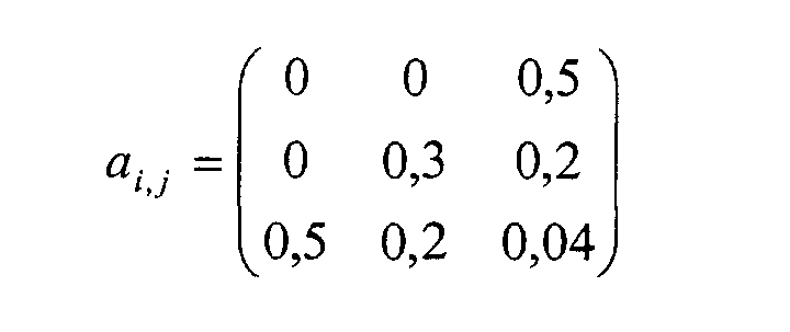
- a mathematical function S (A, B) assigns a number S to each pair of values (A; B).
- a suitable function is e.g. B.
- a i, j parameters by means of which the function can be adapted to the contour of the area T.
- a limit value S G is defined for the function S, which is selected such that the function S (A, B) results in a value smaller than S G for all value pairs (A; B) determined in the learning process.
- the method according to the invention is also in connection with other measuring methods applicable in which properties of a material is determined using microwaves become.
- the characteristic quantities of the microwave field which be determined, e.g. B. also the phase shift of a microwave field Passage through a resonator arrangement or when the measured material is irradiated through a directional radiation field, as well as phases and amplitudes of microwaves reflected on resonator arrangements or irradiated material be determined.
Landscapes
- Physics & Mathematics (AREA)
- General Physics & Mathematics (AREA)
- Pathology (AREA)
- Life Sciences & Earth Sciences (AREA)
- Chemical & Material Sciences (AREA)
- Analytical Chemistry (AREA)
- Biochemistry (AREA)
- General Health & Medical Sciences (AREA)
- Electromagnetism (AREA)
- Health & Medical Sciences (AREA)
- Immunology (AREA)
- Manufacturing Of Cigar And Cigarette Tobacco (AREA)
- Sampling And Sample Adjustment (AREA)
- Investigating Strength Of Materials By Application Of Mechanical Stress (AREA)
- Analysing Materials By The Use Of Radiation (AREA)
- Radar Systems Or Details Thereof (AREA)
- Testing Or Measuring Of Semiconductors Or The Like (AREA)
- Constitution Of High-Frequency Heating (AREA)
Abstract
Description
Als Größen des Mikrowellenfeldes im Sinne der Erfindung werden hier sowohl reale Größen des erzeugten Mikrowellenfeldes, wie Amplitude und Phase bezeichnet, als auch Größen eines das Mikrowellenfeld führenden Bauteiles, wie z. B. die Resonanzfrequenz und die Bandbreite eines Resonators, in welchem sich das Mikrowellenfeld ausbreitet.
Vorzugsweise wird der Materialstrom vor oder nach dem Durchtritt durch den Wirkbereich des Mikrowellenfeldes in Abschnitte unterteilt und solche Abschnitte, bei deren Durchtritt das Signal erzeugt wird, werden nachfolgend aus dem Materialstrom ausgesondert.
3, 4 und 5 zeigen ein bevorzugtes Verfahren zur Vermessung von Resonanzkurven, wie sie in Fig. 2 dargestellt sind.
Bei Betrieb der beschriebenen Vorrichtung bildet sich in der Resonatoranordung 1 aufgrund der Anregung über die Antenne 4 ein stehendes Mikrowellenfeld mit der Frequenz der Anregung aus. Bei Verwendung eines dielektrischen Resonators 21 konzentriert sich dieses Feld hauptsächlich in dessen Inneren. Bei Verwendung eines Hohlraumresonators, z. B. gemäß der genannten DE 198 54 550 A1, füllt das stehende Mikrowellenfeld den gesamten Resonatorinnenraum aus. In beiden Fällen erstreckt sich ein Teil des Mikrowellenfeldes durch das Führungsröhrchen 13 in den Zigarettenstrang 12. Das sich innerhalb der Resonatoranordnung 1 ausbildende stehende Mikrowellenfeld erregt eine Mikrowellenschwingung in der Antenne 6, welche über das Entkopplungsglied 19 zu der Gleichrichterdiode 22 geleitet wird. Die Amplitude des sich in der Resonatoranordnung 1 ausbildenden stehenden Mikrowellenfeldes und damit auch die Amplitude der über die Antenne 6 abgeleiteten Mikrowellenschwingung ist abhängig von der Lage der Frequenz des Mikrowellenfeldes relativ zu der Resonanzfrequenz der Resonatoranordnung 1 und von der Bandbreite der Resonatoranordnung 1. Diese Größen sind in der Beschreibung zur Fig. 2 näher erläutert. Beide Größen werden durch die Wechselwirkung zwischen dem Zigarettenstrang 12 und dem Mikrowellenfeld beeinflusst. Daher sind die Amplituden der sich in der Resonatoranordnung 1 ausbildenden stehenden Mikrowellenfelder bei den nacheinander zugeführten Frequenzen f1 und f2 unterschiedlich und werden durch den Zigarettenstrang 12 auch unterschiedlich beeinflusst, so dass die beiden Amplituden bzw. deren durch die Auswerteschaltung 11 bestimmten Mittelwert 26 und Differenz 27 Aussagen sowohl über das Vorhandensein von Fremdkörpern 34 im Zigarettenstrang 12, als auch über die Tabakdichte 30 und die Tabakfeuchte 29 des im Zigarettenstrang 12 enthaltenen Tabaks 12b ermöglichen.
Die während des Lernprozesses ermittelten Wertepaare der beiden Größen definieren den zulässigen Wertebereich T. Um dieses Gebiet wird eine geschlossene Grenzlinie G gezogen, welche im wesentlichen alle ermittelten Wertepaare umschließt. Diese Grenzlinie kann im einfachsten Fall ein Kreis um das Zentrum Po des Bereiches T sein, dessen Radius so gewählt ist, dass gerade eben alle Punkte in dessen Inneren liegen.
Die Festlegung einer besser angepassten Grenzkurve G kann z. B. durch ein im folgenden beschriebenes mathematisches Verfahren erfolgen.
Über eine mathematische Funktion S(A,B) wird jedem Wertepaar (A;B) eine Zahl S zugeordnet. Eine geeignete Funktion ist z. B.

Zunächst werden der kleinste Wert AS1 und der größte Wert AS2 innerhalb des Wertebereiches T bestimmt und als Grenzwerte für den Wert A3 verwendet. Wenn der zu prüfende Wert A3, wie dargestellt, zwischen diesen beiden Grenzwerten liegt, so kann der Punkt P3 innerhalb des Wertebereiches T liegen. Ansonsten könnte dies ausgeschlossen werden und das Signal würde erzeugt. Danach werden der kleinste Wert BU3 und der größte Wert BO3 ermittelt, welche auf Höhe des Wertes A3 innerhalb des Bereiches T liegen, und als Grenzwerte für den Wert B3 verwendet. Liegt der zu prüfende Wert B3, wie dargestellt, zwischen diesen Grenzwerten, so liegt auch der Punkt P3 innerhalb des Bereiches T, ansonsten würde das Signal erzeugt.
Der zusätzlich dargestellte Punkt P6 liegt deutlich außerhalb des Bereiches T.
Claims (12)
- Verfahren zum Prüfen einer Materialmenge, welche hauptsächlich ein Produktionsmaterial enthält, auf das Vorhandensein eines Fremdmaterials in dieser Menge, bei welchem ein Mikrowellenfeld erzeugt wird, die Materialmenge in den Wirkbereich des Mikrowellenfeldes eingebracht wird und die Beeinflussung des Mikrowellenfeldes analysiert wird, dadurch gekennzeichnet, dass die Istwerte einer ersten und einer zweiten charakteristischen Größe des Mikrowellenfeldes gleichzeitig gemessen werden, dass ein zulässiger Wertebereich für diese Istwerte vorgegeben wird, dass geprüft wird, ob die Istwerte in dem zulässigen Wertebereich liegen und dass ein Signal erzeugt wird, wenn die Istwerte nicht in dem zulässigen Wertebereich liegen.
- Verfahren nach Anspruch 1, dadurch gekennzeichnet, dass der zulässige Wertebereich die Werte der beiden Größen umfasst, welche bei Beeinflussung des Mikrowellenfeldes durch eine Materialmenge auftreten, die ausschließlich das Produktionsmaterial enthält.
- Verfahren nach Anspruch 1 oder 2, dadurch gekennzeichnet, dass das genannte Signal das Vorhandensein von Fremdmaterial in der Materialmenge anzeigt.
- Verfahren nach einem der Ansprüche 1 bis 3, dadurch gekennzeichnet, dass die Materialmenge durch einem Materialstrom gebildet wird, welcher durch den Wirkbereich bewegt wird.
- Verfahren nach Anspruch 5, dadurch gekennzeichnet, dass der Materialstrom durch ein Hüllmaterial umschlossen wird.
- Verfahren nach einem der Ansprüche 1 bis 5, dadurch gekennzeichnet, dass als Produktionsmaterial ein Produktionsmaterial der Tabakverarbeitenden Industrie, insbesondere Tabak oder Filtertow, verwendet wird.
- Verfahren nach einem der Ansprüche 4 bis 6, dadurch gekennzeichnet, dass der Materialstrom vor oder nach dem Durchtritt durch den Wirkbereich in Abschnitte unterteilt wird und dass Abschnitte, bei deren Durchtritt das Signal erzeugt wird, nachfolgend aus dem Materialstrom ausgesondert werden.
- Verfahren nach Anspruch 6 oder 7, dadurch gekennzeichnet, dass das Produktionsmaterial vor dem Durchtritt durch den Wirkbereich zu einem endlosen Strang geformt wird, dass dieser Strang mit einem Hüllstreifen umwickelt wird, dass dieser umhüllte Strang vor oder nach dem Durchtritt durch den Wirkbereich in längliche Abschnitte unterteilt wird, welche zu Zigaretten weiterverarbeitet werden und dass Abschnitte, während deren Durchtritt durch den Wirkbereich das Signal erzeugt wird, vor der Weiterverarbeitung ausgesondert werden.
- Verfahren nach einem der Ansprüche 4 bis 8, dadurch gekennzeichnet, dass der zulässige Wertebereich ermittelt wird, indem eine Referenzmenge, welche ausschließlich das Produktionsmaterial enthält, durch den Wirkbereich bewegt wird und dass die Istwerte, welche während des Durchtritts der Referenzmenge gemessen werden, den zulässigen Wertebereich bilden.
- Verfahren nach Anspruch 9, dadurch gekennzeichnet, dass die Referenzmenge von einem Hüllmaterial umschlossen wird.
- Verfahren einem der vorangehenden Ansprüche, dadurch gekennzeichnet, dass das Verfahren ausgeführt wird, während gleichzeitig unabhängig hierzu aus den Istwerten der selben charakteristischen Größen des Mikrowellenfeldes mindestens eine Eigenschaft des Produktionsmaterials ermittelt wird.
- Verfahren nach Anspruch 12, dadurch gekennzeichnet, dass als Produktionsmaterial Tabak verwendet wird und als Eigenschaft die Dichte und/oder die Feuchte des Tabaks ermittelt wird.
Applications Claiming Priority (2)
| Application Number | Priority Date | Filing Date | Title |
|---|---|---|---|
| DE10100664 | 2001-01-09 | ||
| DE10100664A DE10100664A1 (de) | 2001-01-09 | 2001-01-09 | Verfahren zum Prüfen eines Produktionsmaterials |
Publications (2)
| Publication Number | Publication Date |
|---|---|
| EP1221608A1 true EP1221608A1 (de) | 2002-07-10 |
| EP1221608B1 EP1221608B1 (de) | 2010-10-20 |
Family
ID=7670033
Family Applications (1)
| Application Number | Title | Priority Date | Filing Date |
|---|---|---|---|
| EP01129895A Expired - Lifetime EP1221608B1 (de) | 2001-01-09 | 2001-12-15 | Verfahren zum Prüfen eines Produktionsmaterials in einem Mikrowellenfeld |
Country Status (7)
| Country | Link |
|---|---|
| US (1) | US6768317B2 (de) |
| EP (1) | EP1221608B1 (de) |
| JP (1) | JP4477281B2 (de) |
| CN (1) | CN1368634A (de) |
| AT (1) | ATE485506T1 (de) |
| DE (2) | DE10100664A1 (de) |
| PL (1) | PL207721B1 (de) |
Cited By (1)
| Publication number | Priority date | Publication date | Assignee | Title |
|---|---|---|---|---|
| EP1327876B1 (de) * | 2002-01-11 | 2003-12-17 | TEWS ELEKTRONIK Dipl.-Ing. Manfred Tews | Verfahren und Vorrichtung zur Erkennung von Fremdkörpern in Masseströmen mit Hilfe eines Mikrowellen-Resonators |
Families Citing this family (36)
| Publication number | Priority date | Publication date | Assignee | Title |
|---|---|---|---|---|
| DE10112499B4 (de) | 2001-03-15 | 2010-08-19 | Hauni Maschinenbau Ag | Resonatoreinrichtung, insbesondere Mikrowellenresonatoreinrichtung |
| US7053630B2 (en) * | 2002-07-08 | 2006-05-30 | Saab Rosemount Tank Radar Ab | Level gauging system |
| US8223919B2 (en) | 2003-04-25 | 2012-07-17 | Rapiscan Systems, Inc. | X-ray tomographic inspection systems for the identification of specific target items |
| US8451974B2 (en) | 2003-04-25 | 2013-05-28 | Rapiscan Systems, Inc. | X-ray tomographic inspection system for the identification of specific target items |
| US8837669B2 (en) | 2003-04-25 | 2014-09-16 | Rapiscan Systems, Inc. | X-ray scanning system |
| US9113839B2 (en) | 2003-04-25 | 2015-08-25 | Rapiscon Systems, Inc. | X-ray inspection system and method |
| GB0525593D0 (en) | 2005-12-16 | 2006-01-25 | Cxr Ltd | X-ray tomography inspection systems |
| US8243876B2 (en) | 2003-04-25 | 2012-08-14 | Rapiscan Systems, Inc. | X-ray scanners |
| US20050058242A1 (en) | 2003-09-15 | 2005-03-17 | Peschmann Kristian R. | Methods and systems for the rapid detection of concealed objects |
| US7949101B2 (en) | 2005-12-16 | 2011-05-24 | Rapiscan Systems, Inc. | X-ray scanners and X-ray sources therefor |
| CA2499853C (en) * | 2004-03-15 | 2012-11-13 | Universal Leaf Tobacco Company, Inc. | Apparatus and method for scanning and sorting tobacco leaves |
| DE102004015463B4 (de) * | 2004-03-26 | 2006-07-06 | Hauni Primary Gmbh | Verfahren und Vorrichtung zur Fremdkörperabscheidung |
| DE102004017597B4 (de) * | 2004-04-07 | 2006-06-22 | Hauni Maschinenbau Ag | Resonatorgehäuse für Mikrowellen |
| DE102004063229B4 (de) | 2004-12-22 | 2007-06-14 | Hauni Maschinenbau Ag | Meßvorrichtung und -verfahren zur Erkennung von Fremdkörpern in einem Produkt, insbesondere in Tabak, Baumwolle oder einem anderen Faserprodukt |
| DE102004063228B4 (de) | 2004-12-22 | 2007-06-28 | Hauni Maschinenbau Ag | Meßvorrichtung und -verfahren zur Bestimmung einer dielektrischen Eigenschaft, insbesondere der Feuchte und/oder Dichte, eines Produkts |
| WO2007115416A1 (de) * | 2006-04-07 | 2007-10-18 | Uster Technologies Ag | Verfahren und vorrichtung zur untersuchung von bewegtem, festem, länglichem prüfgut |
| ITBO20060586A1 (it) * | 2006-08-03 | 2006-11-02 | El En Spa | Dispositivo per il taglio laser di un nastro continuo. |
| AT504527B1 (de) * | 2007-02-23 | 2008-06-15 | Evk Di Kerschhaggl Gmbh | Verfahren und vorrichtung zum unterscheiden von ein elektromagnetisches wechselfeld beeinflussenden objekten, insbesondere metallobjekten |
| JP2010535325A (ja) * | 2007-08-02 | 2010-11-18 | ジー.デー ソチエタ ペル アツィオニ | 繊維性材料の特性を検出するための装置 |
| CN101257531B (zh) * | 2008-03-30 | 2013-01-09 | 青岛海信移动通信技术股份有限公司 | 手机结构件中非导电真空电镀件的导电性检测方法及设备 |
| US9310323B2 (en) | 2009-05-16 | 2016-04-12 | Rapiscan Systems, Inc. | Systems and methods for high-Z threat alarm resolution |
| US8281931B2 (en) * | 2009-09-18 | 2012-10-09 | Key Technology, Inc. | Apparatus and method for post-threshing inspection and sorting of tobacco lamina |
| CN102207469B (zh) * | 2010-03-30 | 2013-03-27 | 上海恒博自动化设备有限公司 | 微波离线物料湿度和密度测量方法 |
| DE102010041572B3 (de) * | 2010-09-28 | 2012-03-01 | Hauni Maschinenbau Ag | Vorrichtung und Verfahren zur Verarbeitung und Messung von Eigenschaften eines bewegten Materialstrangs |
| DE102011100244A1 (de) * | 2011-05-02 | 2012-11-08 | Mso Messtechnik Und Ortung Gmbh | Verfahren zur Messung eines leitungsgeführten Gutstroms mittels Microwellen, Sensoranordnung und Vorrichtung mit einer Sensoranordnung |
| CN102323276B (zh) * | 2011-08-04 | 2013-04-17 | 中国电子科技集团公司第四十一研究所 | 一种消除金属外饰影响烟支水分密度测量的方法 |
| JP6017126B2 (ja) * | 2011-09-27 | 2016-10-26 | 旭化成エンジニアリング株式会社 | 異物検出方法及び異物検出装置 |
| DE102012105121A1 (de) * | 2012-06-13 | 2013-12-19 | Hauni Maschinenbau Ag | Messmodul und Messanordnung zum Messen von in Strangmaschinen der Tabak verarbeitenden Industrie hergestellten Strängen und/oder Strangabschnitten sowie Strangmaschine mit solchen Messmodulen bzw. einer solchen Messanordnung |
| CN102621161B (zh) * | 2012-03-31 | 2013-10-16 | 中国科学院长春应用化学研究所 | 一种材料性能参数获取方法 |
| US9823383B2 (en) | 2013-01-07 | 2017-11-21 | Rapiscan Systems, Inc. | X-ray scanner with partial energy discriminating detector array |
| DE102013201512A1 (de) * | 2013-01-30 | 2014-08-14 | Hauni Maschinenbau Ag | Messvorrichtung, Maschine und Verfahren der Tabak verarbeitenden Industrie |
| DE102013223535A1 (de) | 2013-11-19 | 2015-05-21 | Hauni Maschinenbau Ag | Verfahren und Vorrichtung zur Erkennung von Stranginhomogenitäten eines Materialstrangs der Tabak verarbeitenden Industrie |
| US9557427B2 (en) | 2014-01-08 | 2017-01-31 | Rapiscan Systems, Inc. | Thin gap chamber neutron detectors |
| US10345479B2 (en) | 2015-09-16 | 2019-07-09 | Rapiscan Systems, Inc. | Portable X-ray scanner |
| DE202019103894U1 (de) * | 2019-07-15 | 2019-09-23 | Tews Elektronik Gmbh & Co. Kg | Zigarettenmaschine mit einem Saugbandförderer |
| DE102020113167A1 (de) | 2020-05-14 | 2021-11-18 | Thomas Fritsch | Verfahren zur Erfassung von Fremdkörpern und/oder Materialinhomogenitäten innerhalb eines Materialflusses eines landwirtschaftlichen Verbrauchsgutes |
Citations (8)
| Publication number | Priority date | Publication date | Assignee | Title |
|---|---|---|---|---|
| US4514680A (en) * | 1983-01-28 | 1985-04-30 | A.Ahlstrom Osakeyhtio | Flaw detection system using microwaves |
| JPS6345547A (ja) * | 1986-08-13 | 1988-02-26 | Nippon Koshuha Kk | 共振器内を通過する誘電体の内部に存在する導電性異物のマイクロ波による検出方法 |
| EP0337623A2 (de) * | 1988-04-15 | 1989-10-18 | Philip Morris Products Inc. | Verfahren und Vorrichtung zum Erfassen der Abwesenheit eines Gegenstandes in einem Satz von Gegenständen |
| EP0791823A2 (de) * | 1996-02-20 | 1997-08-27 | Hauni Maschinenbau Aktiengesellschaft | Verfahren und Anordnung zum Erfassen mindestens einer Eigenschaft eines Stoffes |
| US5736864A (en) * | 1995-07-14 | 1998-04-07 | Hauni Maschinenbau Ag | Apparatus for ascertaining the complex dielectric constant of tobacco |
| WO2000009983A2 (en) * | 1998-07-30 | 2000-02-24 | Malcam Ltd. | Device and method for non-invasively measuring and determining moisture content and density of loose and packaged tobacco |
| US6163158A (en) * | 1996-02-20 | 2000-12-19 | Hauni Maschinenbau Ag | Method of and apparatus for ascertaining at least one characteristic of a substance |
| WO2001020311A1 (en) * | 1999-09-17 | 2001-03-22 | Sik - Institut För Livsmedel Och Bioteknik Ab | Apparatus and method for detection of foreign bodies in products |
Family Cites Families (11)
| Publication number | Priority date | Publication date | Assignee | Title |
|---|---|---|---|---|
| US4281670A (en) | 1977-06-13 | 1981-08-04 | Hauni-Werke Korber & Co. Kg | Apparatus for increasing the permeability of wrapping material for rod-shaped smokers products |
| IT1137552B (it) | 1980-04-17 | 1986-09-10 | Hauni Werke Koerber & Co Kg | Dispositivo per applicare un liquido plastificante su un nastro di tessuto in movimento |
| US4707652A (en) | 1983-11-30 | 1987-11-17 | Philip Morris Incorporated | Impurity detector measuring parallel polarized scattered electromagnetic radiation |
| US5016653A (en) * | 1986-08-25 | 1991-05-21 | R. J. Reynolds Tobacco Company | Method and apparatus for manufacturing cigarette rods free of metal |
| US4942363A (en) * | 1989-04-25 | 1990-07-17 | Philip Morris Incorporated | Apparatus and method for measuring two properties of an object using scattered electromagnetic radiation |
| US5476108A (en) * | 1990-04-05 | 1995-12-19 | R. J. Reynolds Tobacco Company | Method and apparatus for detecting foreign matter within a layer of tabacco |
| JPH041437U (de) * | 1990-04-17 | 1992-01-08 | ||
| EP0902277A1 (de) * | 1997-08-13 | 1999-03-17 | Hauni Maschinenbau Aktiengesellschaft | Verfahren und Anordnung zum Erfassen mindestens einer Eigenschaft eines Stoffes |
| DE19806125A1 (de) | 1998-02-14 | 1999-08-19 | Hauni Maschinenbau Ag | Vorrichtung zum Entfernen von stabförmigen Artikeln der tabakverarbeitenden Industrie aus Aufnahmen eines umlaufenden Förderers |
| DE19854550C5 (de) | 1998-11-26 | 2011-03-17 | Hauni Maschinenbau Ag | Resonatorgehäuse für Mikrowellen |
| SE517315C2 (sv) * | 1999-09-17 | 2002-05-21 | Sik Inst Foer Livsmedel Och Bi | Apparat och metod för detektering av främmande kroppar i produkter |
-
2001
- 2001-01-09 DE DE10100664A patent/DE10100664A1/de not_active Withdrawn
- 2001-12-15 AT AT01129895T patent/ATE485506T1/de not_active IP Right Cessation
- 2001-12-15 DE DE50115667T patent/DE50115667D1/de not_active Expired - Lifetime
- 2001-12-15 EP EP01129895A patent/EP1221608B1/de not_active Expired - Lifetime
-
2002
- 2002-01-03 US US10/034,258 patent/US6768317B2/en not_active Expired - Fee Related
- 2002-01-07 PL PL351579A patent/PL207721B1/pl unknown
- 2002-01-07 JP JP2002000704A patent/JP4477281B2/ja not_active Expired - Lifetime
- 2002-01-09 CN CN02101535.XA patent/CN1368634A/zh active Pending
Patent Citations (8)
| Publication number | Priority date | Publication date | Assignee | Title |
|---|---|---|---|---|
| US4514680A (en) * | 1983-01-28 | 1985-04-30 | A.Ahlstrom Osakeyhtio | Flaw detection system using microwaves |
| JPS6345547A (ja) * | 1986-08-13 | 1988-02-26 | Nippon Koshuha Kk | 共振器内を通過する誘電体の内部に存在する導電性異物のマイクロ波による検出方法 |
| EP0337623A2 (de) * | 1988-04-15 | 1989-10-18 | Philip Morris Products Inc. | Verfahren und Vorrichtung zum Erfassen der Abwesenheit eines Gegenstandes in einem Satz von Gegenständen |
| US5736864A (en) * | 1995-07-14 | 1998-04-07 | Hauni Maschinenbau Ag | Apparatus for ascertaining the complex dielectric constant of tobacco |
| EP0791823A2 (de) * | 1996-02-20 | 1997-08-27 | Hauni Maschinenbau Aktiengesellschaft | Verfahren und Anordnung zum Erfassen mindestens einer Eigenschaft eines Stoffes |
| US6163158A (en) * | 1996-02-20 | 2000-12-19 | Hauni Maschinenbau Ag | Method of and apparatus for ascertaining at least one characteristic of a substance |
| WO2000009983A2 (en) * | 1998-07-30 | 2000-02-24 | Malcam Ltd. | Device and method for non-invasively measuring and determining moisture content and density of loose and packaged tobacco |
| WO2001020311A1 (en) * | 1999-09-17 | 2001-03-22 | Sik - Institut För Livsmedel Och Bioteknik Ab | Apparatus and method for detection of foreign bodies in products |
Non-Patent Citations (1)
| Title |
|---|
| PATENT ABSTRACTS OF JAPAN vol. 012, no. 255 (P - 732) 19 July 1988 (1988-07-19) * |
Cited By (1)
| Publication number | Priority date | Publication date | Assignee | Title |
|---|---|---|---|---|
| EP1327876B1 (de) * | 2002-01-11 | 2003-12-17 | TEWS ELEKTRONIK Dipl.-Ing. Manfred Tews | Verfahren und Vorrichtung zur Erkennung von Fremdkörpern in Masseströmen mit Hilfe eines Mikrowellen-Resonators |
Also Published As
| Publication number | Publication date |
|---|---|
| EP1221608B1 (de) | 2010-10-20 |
| PL351579A1 (en) | 2002-07-15 |
| US20020121906A1 (en) | 2002-09-05 |
| JP2002233350A (ja) | 2002-08-20 |
| CN1368634A (zh) | 2002-09-11 |
| PL207721B1 (pl) | 2011-01-31 |
| US6768317B2 (en) | 2004-07-27 |
| DE50115667D1 (de) | 2010-12-02 |
| JP4477281B2 (ja) | 2010-06-09 |
| DE10100664A1 (de) | 2002-07-11 |
| ATE485506T1 (de) | 2010-11-15 |
Similar Documents
| Publication | Publication Date | Title |
|---|---|---|
| EP1221608B1 (de) | Verfahren zum Prüfen eines Produktionsmaterials in einem Mikrowellenfeld | |
| EP2042858B1 (de) | Mikrowellenresonatormesseinrichtung | |
| DE69932194T2 (de) | Verfahren zur Erfassung der Feuchtigkeit eines Schüttgutes | |
| DE19705260B4 (de) | Anordnung zum Erfassen mindestens einer dielektrischen Eigenschaft eines Stoffes | |
| EP2848133B1 (de) | Anordnung und Verfahren zur Überprüfung von stabförmigen Artikeln der Tabak verarbeitenden Industrie | |
| EP2207027B1 (de) | Verfahren und Vorrichtung zur Messung der Feuchte von Kapseln in einem Zigarettenfilterstrang, indem dieser durch einen Mikrowellenresonator geführt wird | |
| EP3158325B1 (de) | Mikrowellenmessvorrichtung, anordnung und verfahren zur überprüfung von stabförmigen artikeln oder eines materialstrangs der tabak verarbeitenden industrie sowie maschine der tabak verarbeitenden industrie | |
| DE3905658A1 (de) | Verfahren und vorrichtung zum messen der feuchte eines gutes | |
| EP3354143B1 (de) | Verfahren und vorrichtung zum überwachen und herstellen eines filterstrangs der tabak verarbeitenden industrie | |
| DE3317215C2 (de) | ||
| EP0753755A2 (de) | Vorrichtung zur Messung der komplexen Dielektrizitätskonstanten von Tabak | |
| EP2873334B2 (de) | Verfahren und Vorrichtung zur Erkennung von Stranginhomogenitäten eines Materialstrangs der Tabak verarbeitenden Industrie | |
| EP1480532A1 (de) | Vorrichtung zur gleichzeitigen, kontinuierlichen messung und regelung der acetat- und triacetinmenge in filterstäben in der zigarettenindustrie | |
| EP2069777B1 (de) | Vorrichtung für eine textilmaschine zur messung der längenspezifischen masse und/oder der feuchtigkeit eines strangförmigen, laufenden fasergemenges | |
| EP3281536A1 (de) | Verfahren und vorrichtung zum erkennen und/oder prüfen eines in ein stab- oder strangförmiges produkt der tabak verarbeitenden industrie eingelegten objekts | |
| EP3374762B1 (de) | Vorrichtung und verfahren zur bestimmung des anteils mindestens eines zusatzstoffs in einem tabakhaltigen stoff, und maschine der tabak verarbeitenden industrie | |
| DE4212804A1 (de) | Verfahren und vorrichtung zur inhaltsaktivierung fuer eine automatisierte postentnahmevorrichtung | |
| EP2251679B1 (de) | Vorrichtung und Verfahren zur Messung einer Produkteigenschaft mittels einer Mikrowellen-Streufeldsensoranordnung | |
| DE202006020481U1 (de) | Mikrowellenmessvorrichtung zur Bestimmung mindestens einer Messgröße an einem Produkt | |
| EP3176567A1 (de) | Anordnung, maschine, verfahren und verwendung zum überprüfen einer zigarettenkopfqualität | |
| WO2007140639A1 (de) | Verfahren und vorrichtung zur detektion einer seele in einem coregarn | |
| DE102009024203A1 (de) | Mikrowellensensor und Verfahren zur Bestimmung dielektrischer Materialeigenschaften | |
| WO2002063247A2 (de) | Verfahren und vorrichtung zur grobunterscheidung eines füllgutes in einem behälter in flüssigkeit oder schüttgut | |
| EP1371979B1 (de) | Mikrowellenvorrichtung zur Qualitätsprüfung von strangförmigen Materialien | |
| EP1895290A1 (de) | Mikrowellenmessvorrichtung zur Bestimmung mindestens einer Messgrösse an einem Produkt |
Legal Events
| Date | Code | Title | Description |
|---|---|---|---|
| PUAI | Public reference made under article 153(3) epc to a published international application that has entered the european phase |
Free format text: ORIGINAL CODE: 0009012 |
|
| AK | Designated contracting states |
Kind code of ref document: A1 Designated state(s): AT BE CH CY DE DK ES FI FR GB GR IE IT LI LU MC NL PT SE TR |
|
| AX | Request for extension of the european patent |
Free format text: AL;LT;LV;MK;RO;SI |
|
| 17P | Request for examination filed |
Effective date: 20021107 |
|
| AKX | Designation fees paid |
Designated state(s): AT BE CH CY DE DK ES FI FR GB GR IE IT LI LU MC NL PT SE TR |
|
| 17Q | First examination report despatched |
Effective date: 20050330 |
|
| GRAP | Despatch of communication of intention to grant a patent |
Free format text: ORIGINAL CODE: EPIDOSNIGR1 |
|
| GRAS | Grant fee paid |
Free format text: ORIGINAL CODE: EPIDOSNIGR3 |
|
| GRAA | (expected) grant |
Free format text: ORIGINAL CODE: 0009210 |
|
| AK | Designated contracting states |
Kind code of ref document: B1 Designated state(s): AT BE CH CY DE DK ES FI FR GB GR IE IT LI LU MC NL PT SE TR |
|
| REG | Reference to a national code |
Ref country code: GB Ref legal event code: FG4D Free format text: NOT ENGLISH |
|
| REG | Reference to a national code |
Ref country code: CH Ref legal event code: EP |
|
| REG | Reference to a national code |
Ref country code: IE Ref legal event code: FG4D Free format text: LANGUAGE OF EP DOCUMENT: GERMAN |
|
| REF | Corresponds to: |
Ref document number: 50115667 Country of ref document: DE Date of ref document: 20101202 Kind code of ref document: P |
|
| REG | Reference to a national code |
Ref country code: NL Ref legal event code: VDEP Effective date: 20101020 |
|
| REG | Reference to a national code |
Ref country code: IE Ref legal event code: FD4D |
|
| PG25 | Lapsed in a contracting state [announced via postgrant information from national office to epo] |
Ref country code: FI Free format text: LAPSE BECAUSE OF FAILURE TO SUBMIT A TRANSLATION OF THE DESCRIPTION OR TO PAY THE FEE WITHIN THE PRESCRIBED TIME-LIMIT Effective date: 20101020 Ref country code: NL Free format text: LAPSE BECAUSE OF FAILURE TO SUBMIT A TRANSLATION OF THE DESCRIPTION OR TO PAY THE FEE WITHIN THE PRESCRIBED TIME-LIMIT Effective date: 20101020 Ref country code: PT Free format text: LAPSE BECAUSE OF FAILURE TO SUBMIT A TRANSLATION OF THE DESCRIPTION OR TO PAY THE FEE WITHIN THE PRESCRIBED TIME-LIMIT Effective date: 20110221 Ref country code: SE Free format text: LAPSE BECAUSE OF FAILURE TO SUBMIT A TRANSLATION OF THE DESCRIPTION OR TO PAY THE FEE WITHIN THE PRESCRIBED TIME-LIMIT Effective date: 20101020 |
|
| BERE | Be: lapsed |
Owner name: HAUNI MASCHINENBAU A.G. Effective date: 20101231 |
|
| PG25 | Lapsed in a contracting state [announced via postgrant information from national office to epo] |
Ref country code: GR Free format text: LAPSE BECAUSE OF FAILURE TO SUBMIT A TRANSLATION OF THE DESCRIPTION OR TO PAY THE FEE WITHIN THE PRESCRIBED TIME-LIMIT Effective date: 20110121 |
|
| PG25 | Lapsed in a contracting state [announced via postgrant information from national office to epo] |
Ref country code: IE Free format text: LAPSE BECAUSE OF FAILURE TO SUBMIT A TRANSLATION OF THE DESCRIPTION OR TO PAY THE FEE WITHIN THE PRESCRIBED TIME-LIMIT Effective date: 20101020 Ref country code: ES Free format text: LAPSE BECAUSE OF FAILURE TO SUBMIT A TRANSLATION OF THE DESCRIPTION OR TO PAY THE FEE WITHIN THE PRESCRIBED TIME-LIMIT Effective date: 20110131 Ref country code: MC Free format text: LAPSE BECAUSE OF NON-PAYMENT OF DUE FEES Effective date: 20101231 |
|
| REG | Reference to a national code |
Ref country code: CH Ref legal event code: PL |
|
| PLBE | No opposition filed within time limit |
Free format text: ORIGINAL CODE: 0009261 |
|
| STAA | Information on the status of an ep patent application or granted ep patent |
Free format text: STATUS: NO OPPOSITION FILED WITHIN TIME LIMIT |
|
| PG25 | Lapsed in a contracting state [announced via postgrant information from national office to epo] |
Ref country code: DK Free format text: LAPSE BECAUSE OF FAILURE TO SUBMIT A TRANSLATION OF THE DESCRIPTION OR TO PAY THE FEE WITHIN THE PRESCRIBED TIME-LIMIT Effective date: 20101020 |
|
| REG | Reference to a national code |
Ref country code: FR Ref legal event code: ST Effective date: 20110831 |
|
| 26N | No opposition filed |
Effective date: 20110721 |
|
| GBPC | Gb: european patent ceased through non-payment of renewal fee |
Effective date: 20110120 |
|
| PG25 | Lapsed in a contracting state [announced via postgrant information from national office to epo] |
Ref country code: BE Free format text: LAPSE BECAUSE OF NON-PAYMENT OF DUE FEES Effective date: 20101231 |
|
| PG25 | Lapsed in a contracting state [announced via postgrant information from national office to epo] |
Ref country code: LI Free format text: LAPSE BECAUSE OF NON-PAYMENT OF DUE FEES Effective date: 20101231 Ref country code: FR Free format text: LAPSE BECAUSE OF NON-PAYMENT OF DUE FEES Effective date: 20110103 Ref country code: CH Free format text: LAPSE BECAUSE OF NON-PAYMENT OF DUE FEES Effective date: 20101231 |
|
| REG | Reference to a national code |
Ref country code: DE Ref legal event code: R097 Ref document number: 50115667 Country of ref document: DE Effective date: 20110721 |
|
| PG25 | Lapsed in a contracting state [announced via postgrant information from national office to epo] |
Ref country code: GB Free format text: LAPSE BECAUSE OF NON-PAYMENT OF DUE FEES Effective date: 20110120 |
|
| PG25 | Lapsed in a contracting state [announced via postgrant information from national office to epo] |
Ref country code: AT Free format text: LAPSE BECAUSE OF NON-PAYMENT OF DUE FEES Effective date: 20101215 |
|
| REG | Reference to a national code |
Ref country code: AT Ref legal event code: MM01 Ref document number: 485506 Country of ref document: AT Kind code of ref document: T Effective date: 20101215 |
|
| PG25 | Lapsed in a contracting state [announced via postgrant information from national office to epo] |
Ref country code: CY Free format text: LAPSE BECAUSE OF FAILURE TO SUBMIT A TRANSLATION OF THE DESCRIPTION OR TO PAY THE FEE WITHIN THE PRESCRIBED TIME-LIMIT Effective date: 20101020 |
|
| PG25 | Lapsed in a contracting state [announced via postgrant information from national office to epo] |
Ref country code: LU Free format text: LAPSE BECAUSE OF NON-PAYMENT OF DUE FEES Effective date: 20101215 |
|
| PG25 | Lapsed in a contracting state [announced via postgrant information from national office to epo] |
Ref country code: TR Free format text: LAPSE BECAUSE OF FAILURE TO SUBMIT A TRANSLATION OF THE DESCRIPTION OR TO PAY THE FEE WITHIN THE PRESCRIBED TIME-LIMIT Effective date: 20101020 |
|
| REG | Reference to a national code |
Ref country code: DE Ref legal event code: R081 Ref document number: 50115667 Country of ref document: DE Owner name: HAUNI MASCHINENBAU GMBH, DE Free format text: FORMER OWNER: HAUNI MASCHINENBAU AG, 21033 HAMBURG, DE |
|
| PGFP | Annual fee paid to national office [announced via postgrant information from national office to epo] |
Ref country code: IT Payment date: 20191231 Year of fee payment: 19 |
|
| PGFP | Annual fee paid to national office [announced via postgrant information from national office to epo] |
Ref country code: DE Payment date: 20200102 Year of fee payment: 19 |
|
| REG | Reference to a national code |
Ref country code: DE Ref legal event code: R119 Ref document number: 50115667 Country of ref document: DE |
|
| PG25 | Lapsed in a contracting state [announced via postgrant information from national office to epo] |
Ref country code: IT Free format text: LAPSE BECAUSE OF NON-PAYMENT OF DUE FEES Effective date: 20201215 |
|
| PG25 | Lapsed in a contracting state [announced via postgrant information from national office to epo] |
Ref country code: DE Free format text: LAPSE BECAUSE OF NON-PAYMENT OF DUE FEES Effective date: 20210701 |