EP1220988B1 - Hydro-power generation for a water treatment system - Google Patents
Hydro-power generation for a water treatment system Download PDFInfo
- Publication number
- EP1220988B1 EP1220988B1 EP00978910A EP00978910A EP1220988B1 EP 1220988 B1 EP1220988 B1 EP 1220988B1 EP 00978910 A EP00978910 A EP 00978910A EP 00978910 A EP00978910 A EP 00978910A EP 1220988 B1 EP1220988 B1 EP 1220988B1
- Authority
- EP
- European Patent Office
- Prior art keywords
- rotor
- hydro
- power generation
- generation system
- housing
- Prior art date
- Legal status (The legal status is an assumption and is not a legal conclusion. Google has not performed a legal analysis and makes no representation as to the accuracy of the status listed.)
- Expired - Lifetime
Links
- XLYOFNOQVPJJNP-UHFFFAOYSA-N water Substances O XLYOFNOQVPJJNP-UHFFFAOYSA-N 0.000 title claims abstract description 214
- 238000010248 power generation Methods 0.000 title claims abstract description 93
- 230000005611 electricity Effects 0.000 claims abstract description 43
- 239000007788 liquid Substances 0.000 claims description 39
- 238000000034 method Methods 0.000 claims description 24
- 239000012530 fluid Substances 0.000 claims description 14
- 230000004907 flux Effects 0.000 claims description 14
- 239000003651 drinking water Substances 0.000 claims description 7
- 235000020188 drinking water Nutrition 0.000 claims description 7
- 238000004146 energy storage Methods 0.000 claims description 6
- 238000005259 measurement Methods 0.000 claims description 4
- 238000004519 manufacturing process Methods 0.000 claims description 3
- 238000012423 maintenance Methods 0.000 claims description 2
- 239000000463 material Substances 0.000 description 17
- 230000007246 mechanism Effects 0.000 description 9
- 239000004033 plastic Substances 0.000 description 8
- 238000004804 winding Methods 0.000 description 8
- 239000000356 contaminant Substances 0.000 description 7
- 230000008878 coupling Effects 0.000 description 6
- 238000010168 coupling process Methods 0.000 description 6
- 238000005859 coupling reaction Methods 0.000 description 6
- 229910052751 metal Inorganic materials 0.000 description 6
- 239000002184 metal Substances 0.000 description 6
- 238000005507 spraying Methods 0.000 description 5
- 229910001220 stainless steel Inorganic materials 0.000 description 5
- 239000010935 stainless steel Substances 0.000 description 5
- OKTJSMMVPCPJKN-UHFFFAOYSA-N Carbon Chemical compound [C] OKTJSMMVPCPJKN-UHFFFAOYSA-N 0.000 description 4
- 230000001965 increasing effect Effects 0.000 description 4
- 229910052799 carbon Inorganic materials 0.000 description 3
- 238000004891 communication Methods 0.000 description 3
- 230000001419 dependent effect Effects 0.000 description 3
- 230000000694 effects Effects 0.000 description 3
- 239000003292 glue Substances 0.000 description 3
- 238000012546 transfer Methods 0.000 description 3
- XEEYBQQBJWHFJM-UHFFFAOYSA-N Iron Chemical compound [Fe] XEEYBQQBJWHFJM-UHFFFAOYSA-N 0.000 description 2
- 229910010293 ceramic material Inorganic materials 0.000 description 2
- 239000004020 conductor Substances 0.000 description 2
- 238000011109 contamination Methods 0.000 description 2
- 210000005069 ears Anatomy 0.000 description 2
- -1 for example Substances 0.000 description 2
- ZZUFCTLCJUWOSV-UHFFFAOYSA-N furosemide Chemical compound C1=C(Cl)C(S(=O)(=O)N)=CC(C(O)=O)=C1NCC1=CC=CO1 ZZUFCTLCJUWOSV-UHFFFAOYSA-N 0.000 description 2
- 230000005484 gravity Effects 0.000 description 2
- 239000003673 groundwater Substances 0.000 description 2
- 238000012986 modification Methods 0.000 description 2
- 230000004048 modification Effects 0.000 description 2
- 230000035515 penetration Effects 0.000 description 2
- 239000007921 spray Substances 0.000 description 2
- 239000002352 surface water Substances 0.000 description 2
- 239000004593 Epoxy Substances 0.000 description 1
- 229910000831 Steel Inorganic materials 0.000 description 1
- 239000004809 Teflon Substances 0.000 description 1
- 229920006362 Teflon® Polymers 0.000 description 1
- 238000004026 adhesive bonding Methods 0.000 description 1
- 229910052782 aluminium Inorganic materials 0.000 description 1
- XAGFODPZIPBFFR-UHFFFAOYSA-N aluminium Chemical compound [Al] XAGFODPZIPBFFR-UHFFFAOYSA-N 0.000 description 1
- 239000011805 ball Substances 0.000 description 1
- 230000015572 biosynthetic process Effects 0.000 description 1
- 239000003990 capacitor Substances 0.000 description 1
- 239000000919 ceramic Substances 0.000 description 1
- 230000005465 channeling Effects 0.000 description 1
- 238000006243 chemical reaction Methods 0.000 description 1
- 230000001276 controlling effect Effects 0.000 description 1
- 238000001816 cooling Methods 0.000 description 1
- 238000005260 corrosion Methods 0.000 description 1
- 230000007797 corrosion Effects 0.000 description 1
- 238000013461 design Methods 0.000 description 1
- 229910002804 graphite Inorganic materials 0.000 description 1
- 239000010439 graphite Substances 0.000 description 1
- 230000036541 health Effects 0.000 description 1
- 230000001939 inductive effect Effects 0.000 description 1
- 238000002347 injection Methods 0.000 description 1
- 239000007924 injection Substances 0.000 description 1
- 238000009434 installation Methods 0.000 description 1
- 229910052742 iron Inorganic materials 0.000 description 1
- 238000003475 lamination Methods 0.000 description 1
- 238000005461 lubrication Methods 0.000 description 1
- 230000002906 microbiologic effect Effects 0.000 description 1
- 244000005700 microbiome Species 0.000 description 1
- 238000013508 migration Methods 0.000 description 1
- 230000005012 migration Effects 0.000 description 1
- 238000012806 monitoring device Methods 0.000 description 1
- 238000000465 moulding Methods 0.000 description 1
- 238000005381 potential energy Methods 0.000 description 1
- 230000005855 radiation Effects 0.000 description 1
- 230000001105 regulatory effect Effects 0.000 description 1
- 239000011435 rock Substances 0.000 description 1
- 239000010865 sewage Substances 0.000 description 1
- 239000005413 snowmelt Substances 0.000 description 1
- 239000002689 soil Substances 0.000 description 1
- 239000007787 solid Substances 0.000 description 1
- 230000006641 stabilisation Effects 0.000 description 1
- 238000011105 stabilization Methods 0.000 description 1
- 230000000087 stabilizing effect Effects 0.000 description 1
- 239000010959 steel Substances 0.000 description 1
- 238000003860 storage Methods 0.000 description 1
- 239000000126 substance Substances 0.000 description 1
- 239000008400 supply water Substances 0.000 description 1
- 238000004078 waterproofing Methods 0.000 description 1
- 238000003466 welding Methods 0.000 description 1
Images


Classifications
-
- F—MECHANICAL ENGINEERING; LIGHTING; HEATING; WEAPONS; BLASTING
- F03—MACHINES OR ENGINES FOR LIQUIDS; WIND, SPRING, OR WEIGHT MOTORS; PRODUCING MECHANICAL POWER OR A REACTIVE PROPULSIVE THRUST, NOT OTHERWISE PROVIDED FOR
- F03B—MACHINES OR ENGINES FOR LIQUIDS
- F03B13/00—Adaptations of machines or engines for special use; Combinations of machines or engines with driving or driven apparatus; Power stations or aggregates
-
- F—MECHANICAL ENGINEERING; LIGHTING; HEATING; WEAPONS; BLASTING
- F05—INDEXING SCHEMES RELATING TO ENGINES OR PUMPS IN VARIOUS SUBCLASSES OF CLASSES F01-F04
- F05B—INDEXING SCHEME RELATING TO WIND, SPRING, WEIGHT, INERTIA OR LIKE MOTORS, TO MACHINES OR ENGINES FOR LIQUIDS COVERED BY SUBCLASSES F03B, F03D AND F03G
- F05B2220/00—Application
- F05B2220/60—Application making use of surplus or waste energy
- F05B2220/602—Application making use of surplus or waste energy with energy recovery turbines
-
- Y—GENERAL TAGGING OF NEW TECHNOLOGICAL DEVELOPMENTS; GENERAL TAGGING OF CROSS-SECTIONAL TECHNOLOGIES SPANNING OVER SEVERAL SECTIONS OF THE IPC; TECHNICAL SUBJECTS COVERED BY FORMER USPC CROSS-REFERENCE ART COLLECTIONS [XRACs] AND DIGESTS
- Y02—TECHNOLOGIES OR APPLICATIONS FOR MITIGATION OR ADAPTATION AGAINST CLIMATE CHANGE
- Y02B—CLIMATE CHANGE MITIGATION TECHNOLOGIES RELATED TO BUILDINGS, e.g. HOUSING, HOUSE APPLIANCES OR RELATED END-USER APPLICATIONS
- Y02B10/00—Integration of renewable energy sources in buildings
- Y02B10/50—Hydropower in dwellings
-
- Y—GENERAL TAGGING OF NEW TECHNOLOGICAL DEVELOPMENTS; GENERAL TAGGING OF CROSS-SECTIONAL TECHNOLOGIES SPANNING OVER SEVERAL SECTIONS OF THE IPC; TECHNICAL SUBJECTS COVERED BY FORMER USPC CROSS-REFERENCE ART COLLECTIONS [XRACs] AND DIGESTS
- Y02—TECHNOLOGIES OR APPLICATIONS FOR MITIGATION OR ADAPTATION AGAINST CLIMATE CHANGE
- Y02E—REDUCTION OF GREENHOUSE GAS [GHG] EMISSIONS, RELATED TO ENERGY GENERATION, TRANSMISSION OR DISTRIBUTION
- Y02E10/00—Energy generation through renewable energy sources
- Y02E10/20—Hydro energy
-
- Y—GENERAL TAGGING OF NEW TECHNOLOGICAL DEVELOPMENTS; GENERAL TAGGING OF CROSS-SECTIONAL TECHNOLOGIES SPANNING OVER SEVERAL SECTIONS OF THE IPC; TECHNICAL SUBJECTS COVERED BY FORMER USPC CROSS-REFERENCE ART COLLECTIONS [XRACs] AND DIGESTS
- Y02—TECHNOLOGIES OR APPLICATIONS FOR MITIGATION OR ADAPTATION AGAINST CLIMATE CHANGE
- Y02E—REDUCTION OF GREENHOUSE GAS [GHG] EMISSIONS, RELATED TO ENERGY GENERATION, TRANSMISSION OR DISTRIBUTION
- Y02E10/00—Energy generation through renewable energy sources
- Y02E10/30—Energy from the sea, e.g. using wave energy or salinity gradient
-
- Y—GENERAL TAGGING OF NEW TECHNOLOGICAL DEVELOPMENTS; GENERAL TAGGING OF CROSS-SECTIONAL TECHNOLOGIES SPANNING OVER SEVERAL SECTIONS OF THE IPC; TECHNICAL SUBJECTS COVERED BY FORMER USPC CROSS-REFERENCE ART COLLECTIONS [XRACs] AND DIGESTS
- Y10—TECHNICAL SUBJECTS COVERED BY FORMER USPC
- Y10S—TECHNICAL SUBJECTS COVERED BY FORMER USPC CROSS-REFERENCE ART COLLECTIONS [XRACs] AND DIGESTS
- Y10S415/00—Rotary kinetic fluid motors or pumps
- Y10S415/905—Natural fluid current motor
Definitions
- the present invention relates generally to a water treatment system and, more particularly, to a method and system for providing electrical power to a water treatment system through hydroelectric power generation.
- a clean, constant supply of drinking water is essential to every community. People in large cities frequently drink water that comes from surface water sources, such as lakes, rivers, and reservoirs. Sometimes these sources are close to the community and other times, drinking water is obtained from sources many miles away. In rural areas, people are more likely to drink ground water that is pumped from public or private wells. These wells tap into aquifers that may be only a few miles wide, or may span the borders of many states. Although efforts are made to limit the levels of contaminants in ground water and surface water, some level of contaminants is present in all drinking water.
- a power source In order to energize the ultraviolet light unit and a plurality of other systems in the water treatment system, a power source is required.
- Conventional water treatment systems use power from a standard electrical outlet or a battery power source to provide the energy necessary to drive all of the components in the water treatment system, including the ultraviolet light unit.
- the system In the case of water treatment systems powered by electrical outlets, the system has limited portability and ceases to operate when there is an interruption in the electrical outlet power supply.
- Water treatment systems operated from battery power sources contain only a finite supply of energy that is depleted through operation or storage of the water treatment system and replacement batteries must be readily available to keep the water treatment system operable. If a longer-term battery power source is desired, larger batteries are required that can add considerable weight and size to the water treatment system.
- Some existing water treatment systems are capable of using either the standard electrical outlets or the battery power sources where the battery power source can be replenished by the electrical outlet power source. Although these water treatment systems do not require replacement batteries, the capacity and size of the batteries dictate the length of operation of the water treatment system while operating on the battery source. An electrical outlet source must also be utilized on a regular basis to replenish the batteries. In addition, these water treatment systems require additional electrical circuits and components to operate from the two different power sources.
- US -A- 4,443,707 discloses a hydroelectric generating system, which produces power by changing the potential energy of water to kinetic energy to drive a turbine that is coaxially connected to a generator.
- US -A- 5,389,821 discloses a drainwater/sewage treatment installation for producing electrical power and for regulating waterflow in a drainage network.
- US -A- 4,555,637 discloses a high-speed turbogenerator functionally combining, in one machine, an electrical generator and an expansion turbine.
- the present invention discloses a hydro-power generation system for use in conjunction with a water treatment system that overcomes problems associated with the prior art.
- the embodiments of the hydro-power generation system require no external power source to provide power for use by the water treatment system.
- the hydro-power generation system is operable to produce electricity when water is flowing through the water treatment system.
- This present invention provides a hydro-power generation system, comprising:
- the present invention also provides a method of supplying electricity using a flow of liquid, the method comprising:
- the presently preferred embodiments can be readily adapted for use in a variety of water treatment systems that require a power source, such as portable water treatment systems, faucet-mounted water treatment systems, under-counter water treatment systems, whole house water treatment systems and remote location water treatment systems.
- a power source such as portable water treatment systems, faucet-mounted water treatment systems, under-counter water treatment systems, whole house water treatment systems and remote location water treatment systems.
- the hydro-power generation system could be adapted for use with various other systems that require electricity during activities that include flowing water or other fluids.
- the presently preferred water treatment system contains a self-sustaining power supply, the standard electrical outlet power supply is not required.
- the water treatment system since the water treatment system is capable of supplying its own power needs, it can also provide a power source for charging an energy storage device used for the water treatment system.
- the energy storage device may augment operation by providing power for such things as indicators and monitors during times when the water is not flowing.
- the hydro-power generation system may provide power for initial power requirements, UV lamp starting, indicators and monitoring devices.
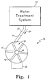
- Fig. 1 is a side view of a water treatment system 10 connected with a hydro-power generation system 12.
- the hydro-power generation system 12 includes a nozzle 14, a housing 16, an impeller 18 and a housing outlet 20.
- the nozzle 14 is coupled with the water treatment system 10 by a conduit 22.
- the conduit 22 may be formed of PVC plastic or similar material and may be coupled to the nozzle 14 by threaded connection, friction fit or some other similar connection mechanism.
- pressurized water flows from the water treatment system 10 into the hydro-power generation system 12 via the nozzle 14 as illustrated by arrow 24.
- the nozzle 14 is coupled with the housing 16 such that water flows through the nozzle 14 and is forced through the housing 16 to the housing outlet 20.
- the hydro-power generation system 12 may be positioned within the water treatment system 10 or positioned to receive a supply of pressurized water before the water enters the water treatment system 10
- Fig. 2 illustrates a cross section of a nozzle 14.
- the preferred nozzle 14 is a sonic nozzle that increases the velocity of pressurized water flowing therethrough.
- the nozzle 14 may be capable of increasing the velocity of the water to sub-sonic speed.
- the nozzle 14 is formed of stainless steel or some other similar rigid material and includes a nozzle inlet 26 and a nozzle outlet 28.
- the nozzle inlet 26 is coupled to the water treatment system 10 as previously discussed.
- the nozzle outlet 28 is coupled to the housing 16 by friction fit, snap-fit, threaded connection or some other similar coupling mechanism capable of forming a watertight connection therebetween.
- the nozzle 14 may penetrate the housing 16 in any location that provides proper alignment of the nozzle 14 with the impeller 18 as will be hereinafter discussed.
- the nozzle 14 includes a passageway 30 that provides for the flow of water therethrough.
- the passageway 30 is formed to be a first predetermined diameter 32 at the nozzle inlet 26 and a second predetermined diameter 34 at the nozzle outlet 28.
- the second predetermined diameter 34 may be about twenty-six percent of the first predetermined diameter 32.
- the passageway 30 remains the first predetermined diameter 32 for a predetermined length of the nozzle 14.
- the remaining portion of the passageway 30 is conically shaped by uniformly tapering the passageway 30 to the second predetermined diameter 34.
- the passageway 30 of the nozzle 14 in Figure 2 tapers at an angle of approximately 18 degrees between the first predetermined diameter 32 and the second predetermined diameter. 34.
- the configuration of the passageway 30 determines the velocity of the water exiting from the nozzle 14.
- the velocity of the water at the nozzle outlet 28 is dependent on the pressure of the water source and the back pressure downstream of the nozzle 14.
- a desirable predetermined range of the velocity at the nozzle outlet 28 may be determined using an expected range of pressure provided by the water treatment system 10 (illustrated in Fig. 1) at the nozzle inlet 26.
- the pressure of the water supply is in a range of about 137.88 x 10 3 to 413.64 x 10 3 Pa (twenty to sixty pounds-per-square-inch (PSI)).
- PSI forty pounds-per-square-inch
- the passageway 30 also provides a continuous and uniform stream of water at the nozzle outlet 28. During operation water flowing through the nozzle 14 flows into the housing 16 within a predetermined range of high velocity with a predetermined trajectory.
- the housing 16 forms a conduit that may be composed of plastic or some other similar waterproof material capable of forming a rigid passageway for water.
- the housing 16 may include a translucent portion as illustrated in Fig. 1 to allow viewing of the interior of the housing 16.
- the housing 16 is formed to encompass the impeller 18 that is in fluid communication with water as the water flows through the housing 16 after exiting the nozzle outlet 28.
- the impeller 18 includes a plurality of blades 42 that are rigidly fastened to a hub 44.
- the blades 42 are positioned in the housing 16 such that water flowing from the nozzle 14 impinges upon the blades 42 of the impeller 18 at a predetermined angle.
- the predetermined angle is determined based on the expected pressure of the water at the nozzle inlet 26, the back pressure at the nozzle outlet 28 and the desired revolutions-per-minute (RPM) of the impeller 18.
- RPM revolutions-per-minute
- the flowing water acts on the impeller 18 causing it to rotate in a single direction within the housing 16.
- the hydro-power generation system 12 converts the energy in the flowing water to rotational energy, which is then converted to electricity.
- Impeller 18 is submerged in the water flowing through the housing 16.
- Fig. 3 illustrates the water treatment system depicted in Fig. 1 rotated 90 degrees with a portion of the housing 16 sectioned away.
- the impeller 18 is coaxially fastened to a generator 46 by a longitudinal extending shaft 48.
- the shaft 48 may be stainless steel or some other similar rigid material that is fixedly coupled with the impeller 18.
- the hub 44 of the impeller 18 is coaxially coupled to one end of the shaft 48 and a generator shaft 50, which is part of the generator 46, is coaxially coupled to the other end.
- the rigid coupling of the shaft 48 to the impeller 18 and the generator 46 may be by welding, press-fit or other similar rigid connection.
- the rotatable shaft 48 longitudinally extends to penetrate the housing 16 through a watertight seal 52 made of rubber or other similar material.
- the watertight seal 52 is coupled to the housing 16 and is formed to allow the shaft 48 to rotate freely without the escape of water from within the housing 16.
- the shaft 48 longitudinally extends to the generator 46 that is positioned adjacent the housing 16.
- the outer surface of the generator 46 may be coupled to the housing 16 by, for example, nuts and bolts, rivets or other similar mechanism capable of fixedly coupling the housing 16 and generator 46.
- the impeller 18 During operaton, as water flows through the housing 16 and the impeller 18 rotates, shafts 48, 50 correspondingly rotate, causing electricity to be produced from the generator 46.
- a magnetic coupler (not shown) is used in place of the shaft 48 to eliminate the need for penetration of the housing 16.
- the impeller 18 includes magnets with sufficient magnetic strength to rigidly couple with similar magnets positioned on the generator shaft 50 outside the housing 16.
- the magnetic attraction of the magnets oriented on the impeller and the magnets oriented on the generator shaft 50 cause rotation of the generator shaft 50 thereby generating electricity from the generator 46.
- Generator 46 may be a permanent magnet generator capable of generating direct current (DC) or alternating current (AC). Alternatively, the generator 46 may be capable of generating both AC and DC current.
- the stet Electricity is transferred from the generator 46 by a plurality of conductors 54 that may be wires, busses or other similar materials capable of conducting electricity.
- the voltage level of the electricity produced is a function of the revolutions-per-minute of the impeller 18. As previously discussed, the velocity of the water flowing from the nozzle 14 may be designed within a predetermined range thereby controlling the voltage output of the electricity generated by the generator 46.
- the direct or alternating current produced by the generator 46 may be used to power the water treatment system 10 and may also be used to charge an energy storage device (not shown) such as, for example, a battery or capacitors.
- the rotation of the impeller 18 or the duration of the electricity being produced may also provide a mechanism for flow-based measurements such as, flow rates or the quantity of water that has flowed through the water treatment system 10.
- the rotation of the impeller 18 or the duration of the electricity being produced may be combined with the back electromagnetic force (EMF) of the generator 46 to provide the flow-based measurements.
- EMF back electromagnetic force
- Fig. 4 illustrates a cross sectional view of another embodiment of the hydro-power generation system 12.
- This embodiment is similarly coupled to the water treatment system 10 as in the embodiment illustrated in Fig. 1 and includes a nozzle 14, a housing 16, an impeller 18 and a housing outlet 20.
- the nozzle 14 provides water at high velocity that is directed at the rotatable impeller 18.
- the impeller 18 is not submerged in water within the housing 16 during operation. As such, the water from the nozzle 14 forms a stream that is sprayed at the impeller 18.
- the nozzle 14 may be a sonic nozzle similar to the previously discussed nozzle 14 illustrated in Fig. 2.
- the nozzle 14 penetrates the housing 16 and is coupled thereto by a mounting plate 56.
- the mounting plate 56 is positioned adjacently contacting the outer surface of the housing 16. Those skilled in the art would recognize that other methods exist that could be used to couple the nozzle 14 with the housing 16.
- Fig. 5 illustrates a cross sectional view of the nozzle 14 mounted in a mounting plate 56.
- the mounting plate 56 includes a longitudinal slot 58 and a pair of ears 60 that allow adjustment of the nozzle 14 to an optimal position in relation to the impeller 18.
- Nozzle 14 may be fixedly mounted to the housing 16 when the optimal position is achieved by inserting threaded screws in the ears 60.
- the mounting plate 56 provides a single predetermined desired position of the nozzle 14 when the fasteners such as, for example, threaded screws, rivets or pins fixedly mount the mounting plate 56 on the housing 16.
- the desired position of the nozzle 14 is such that the nozzle 14 longitudinally extends into the housing 16.
- the housing 16 includes a housing cavity 62 that is defined by the inner walls of the housing 16 as illustrated in Fig. 4.
- the housing cavity 62 is an air space that includes the impeller 18 positioned therein.
- water is sprayed from the nozzle 14 into the housing cavity 62 with a predetermined trajectory to strike the impeller 18 at a predetermined angle.
- the predetermined angle is based on the desired RPM of the impeller 18 and the range of the pressure of water supplied to the nozzle 14 from the water treatment system 10.
- the cooperative operation of the nozzle 14 and the impeller 18 are not limited to operation with pressurized water and other fluids such as, for example, air could similarly be utilized.
- the impeller 18 includes a plurality of blades 64.
- Each of the blades 64 are fixedly coupled to an impeller hub 66 at one end and include a paddle 68 formed at the opposite end.
- the impeller hub 66 is fixedly coupled to a shaft 48 as previously discussed above.
- the quantity of the blades 64 and the size of the impeller 18 could vary depending on the application.
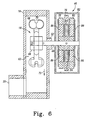
- Fig. 6 illustrates the hydro-power generation system 12 illustrated in Fig. 5 rotated 90 degrees with a portion of the housing 16 sectioned away for illustrative purposes.
- the hydro-power generation system 12 includes the housing 16 coupled to the generator 46 with the shaft 48 as in the previously discussed embodiments.
- the shaft 48 which is rotatable, longitudinally extends from the impeller 18 into the generator 46 through the watertight seal 52.
- the shaft 48 could be modified with a magnetic coupler, as previously described, thereby eliminating the penetration of the housing 16 and the watertight seal 52.
- the shaft 48 rotatably positions the impeller 18 in the airspace within the housing cavity 62 with the paddles 68 thereby rotating about the shaft 48.
- each of the paddles 68 are formed in a parabolic shape that includes a slot 70.
- the parabolic shape of the paddles 68 provide a uniform receiver of the energy present in the water spraying from the nozzle 14 (illustrated in Fig. 5).
- the slots 70 allow the energy of the spraying water to pass to the next paddle 68 as the impeller 18 rotates.
- the transitional passing of the energy in the spraying water to the next paddle 68 maximizes the efficiency of the energy transfer from the water to the impeller 18.
- the blades 64 could be formed in other shapes and configurations that are conducive to the efficient transfer of energy from other fluids sprayed from the nozzle 14.
- the blades 64 may be formed as vanes, fins or other similar structure capable of translating the energy from the flowing air to the rotation of the impeller 18.
- the water falls by gravity as indicated by arrow 72 toward the housing outlet 20. As such, the water collects at the housing outlet 20 and is thereby channeled out of the housing 16. Since the impeller 18 is not submerged in water, the bulk of the energy transferred from the water stream to the impeller 18 is provided as rotational force to the shaft 48.
- the rotation of the shaft 48 causes rotation of a portion of the generator 46.
- One embodiment of the generator 46 includes a rotor 76, a first stator 78, and a second stator 80 positioned within a generator housing 82.
- the rotor 76 is fixedly coupled to the shaft 48 and rotates therewith.
- the first and second stators 78, 80 are fixedly coupled to the generator housing 82 and circumferentially surround the shaft 48.
- the rotor 76 is positioned between the first and second stators 78, 80 to form the generator 46.
- the rotor 76 may be in the form of a disk that includes a plurality of permanent magnets 84.
- the permanent magnets 84 are uniformly place in predetermined positions within the rotor 76 to operatively cooperate with the first and second stators 78, 80.
- Each of the first and second stators 78, 80 in this embodiment may also form disks that include a plurality of coils 86.
- the coils 86 are positioned uniformly within the first and second stators 78, 80 to operatively cooperate with the permanent magnets 84.
- the coils 86 may be electrically connected to form one or more windings that are operable to generate electricity.
- the number of poles and the design of the first and second stators 78, 80 are dependent on a number of factors. The factors include: the strength of the gaussian field formed by the permanent magnets 84 and the back EMF, as well as the desired RPM and the desired power output of the generator 46.
- the rotation of the rotor 76 causes magnetic flux that is generated by the permanent magnets 84 to similarly rotate thereby producing electricity in the first and second stators 78, 80.
- the rotor 76 and the first and second stators 78, 80 operatively cooperate to generate alternating current (AC).
- the AC may be rectified and stabilized by the generator 46 to supply both AC and direct current (DC).
- the permanent magnets 84 may be positioned on the first and second stators 78, 80 such that the generator 46 is operable to generate direct current (DC).
- the generator 46 is similar to the generator 46 discussed with reference to Fig. 3.
- pressurized water may be supplied from the water treatment system 10 (illustrated in Fig. 1) to the hydro-power generation system 12.
- the hydro-power generation system 12 may supply water to the water treatment system 10 or be positioned within the water treatment system 10. Water is supplied from the water treatment system 10 to the nozzle 14, as previously discussed.
- the energy in the spraying water is translated to the impeller 18 causing rotation in a single direction.
- a portion ofthe spraying water also sprays through the slots 70 and strikes another of the paddles 68 on the impeller 18.
- the water falls by gravity to the housing outlet 20 and flows out of the housing 16. Accordingly, the housing cavity 62 remains an airspace during operation and is not completely filled with water during operation.
- the rotation of the impeller 18 causes rotation of the shaft 48 thereby rotating the rotor 76 of the generator 46.
- the rotor 76 rotates at about 2400 revolutions-per-minute (RPM). Rotation of the rotor 76 induces the generation of electricity that is supplied to the water treatment system 10.
- the range of the voltage level produced by the generator 46 is based on the range of velocity of the water flowing through the nozzle 14. Accordingly, the voltage range of the generator can be selected by selecting a predetermined range of velocity for the flowing water through the nozzle 14
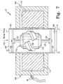
- Fig. 7 illustrates a cross-sectional view of an hydro-power generation system 12 which is preferentially coupled with the water treatment system 10.
- the hydro-power generation system 12 includes a rotor housing 102 and a stator housing 104.
- the rotor housing 102 forms a conduit that may be composed of plastic or other similar rigid material and includes an inlet 106 and an outlet 108.
- the inlet 106 receives the flowing water as illustrated by arrow 110 and the outlet 108 channels the flowing water to the water treatment system 10.
- the hydro-power generation system 12 may be positioned within the water treatment system 10 or positioned to receive water flowing out of the water treatment system 10. As previously discussed, the flow of water through the hydro-power generation system 12 may be controlled by the water treatment system 10.
- the rotor housing 102 contains a rotor 112 and the stator housing 104 contains a stator 114.
- the rotor 112 of this hydro-power generation system may be a twelve-pole permanent magnet rotor having six north/south pole combinations.
- the stator 114 of this system may be an annular ring designed with eight north/south pole combinations.
- the rotor 112 and the stator 114 cooperatively operate to produce electricity during operation.
- a stator contains a stationary winding that can be configured to contain any number of poles depending on the magnitude of the voltage needed at the output. The number of poles in the winding disclosed in the present embodiment should not be construed as a limitation on the present invention.
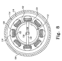
- Fig. 8 illustrates a top view of the hydro-power generation system depicted in Fig. 7 with the top portion of the stator housing 104 sectioned away for illustrative purposes.
- the stator 114 is fixedly positioned in the stator housing 104 to circumferentially surround the rotor housing 102.
- the stator 114 includes a core 116, a plurality of salient poles 118 and a plurality of coils 120.
- the core 116 may be composed of iron, steel or other similar material and is formed to include the salient poles 118. In this embodiment, there may be eight salient poles 118 that are each surrounded by coils 120.
- the salient poles 118 are formed on the stator 114 such that they circumferentially surround the rotor housing 102.
- Each of the salient poles 118 includes a formed end that is known in the art as a pole shoe 122.
- the pole shoes 122 are located adjacent the rotor housing 102.
- the pole shoes 122 conduct a constant magnetic flux formed by the rotor 112 through the coils 120.
- the coils 120 may be wire or some other similar material capable of conducting electricity and being wrapped around the salient poles 118. Although not illustrated, the coils 120 are electrically connected to form the winding.
- the number of turns of wire used for each coil 120 is determined by the voltage and power requirements, the minimum and maximum revolutions of the rotor 112, the maximum allowable back-pressure, the required inductance and the magnetic gauss.
- the stator 114 is transversely positioned perpendicular to the central axis of the rotor housing 102. Since the stator 114 is positioned outside the rotor housing 102, it is isolated from fluid communication with the water flowing within the rotor housing 102.
- the stator housing 104 is fixedly coupled to the rotor housing 102 thereby providing a predetermined position on the rotor housing 102 for the stator 114. In this system, the stator housing 104 is coupled with the external surface of the rotor housing 102 by a friction fit.
- Those skilled in the art would recognize that various other ways of coupling the rotor housing 102 and the stator housing 104 exist.
- the rotor 112 includes a permanent magnet 124 that can be formed of metal, sintered metal, extruded metal or ceramic material.
- the permanent magnet 124 forms a constant magnetic flux and is coupled with a rotor shaft 126.
- the rotor shaft 126 which is rotatable, longitudinally extends from opposite ends of the permanent magnet 124 and may be composed of stainless steel or other rigid, corrosion resistant material.
- the permanent magnet 124 is formed with its central axis coaxial with the rotor shaft 126.
- the outer surface of the permanent magnet 124 may be formed in a streamline shape to include at least one rotor blade 128.
- the permanent magnet 124 of this system is formed in a barrel shape with a single helical ridge forming the rotor blade 128.
- the rotor blade 128 could be turbine blades or other similar devices capable of inducing rotation of the rotor 112 when subjected to flowing water.
- the rotor 112 is positioned within the rotor housing 102 coaxial with the central axis of the rotor housing 102.
- One end of the rotor shaft 126 of the rotor 112 is inserted in a first collar 130 and the other end of the rotor shaft 126 is inserted in a second collar 132.
- the ends of the rotor shaft 126 increase in diameter to form a solid sphere to facilitate fastening to the first collar 130 and the second collar 132.
- the first collar 130 and the second collar 132 are formed of plastic or other similar material and create a transverse strut perpendicular to the central axis of the rotor housing 102.
- the first collar 130 and the second collar 132 each contain a bearing 134 or other similar device to allow the rotor shaft 126 to rotate freely. Additionally, the first collar 130 and the second collar 132 are coupled to the rotor housing 102 at a predetermined distance from each other such that the rotor 112 can be suspended therebetween.
- the rotor 112 is positioned in the rotor housing 102 such that water flowing through the rotor housing 102 impinges upon the rotor blade 128 that forms a part of the rotor 112.
- the rotor blade 128 acts as a paddle, causing the flowing water to act on the rotor 112.
- the flowing water causes the rotor 112 to rotate in a single direction about the central axis of the rotor housing 102.
- the rotor 112 is positioned within the stator 114 such that the axis of the rotor 112 is concentric with that of the stator 114.
- the rotor 112 operatively cooperates with the stator 144 to form the generator.
- the constant magnetic flux generated by the rotor 112 also rotates and penetrates into the stator 114 thereby intrinsically creating power.
- An air gap of a specified distance must be maintained between the rotor 112 and the stator 114 to allow the constant magnetic flux from the rotor 112 to induce the generation of electricity from the stator 114.
- the "air gap" between the permanent magnet 124 of the rotor 112 and the pole shoes 122 of the stator 114 consists of flowing water and the rotor housing 102. The flow of fluid and the rotor housing 102 do not affect the constant magnetic flux. Accordingly, the rotating constant magnetic flux from the rotating rotor 112 induces the production of electricity from the coils 120 of the stator 114.
- the hydro-power generation system 12 illustrated in Figs. 7 and 8 produces alternating current (AC) that may be used to power the water treatment system 10.
- the hydro-power generation system 12 may produce direct current (DC) by positioning the permanent magnet on the stator 114.
- the hydro-power generation system 12 supplies both AC and DC current to the water treatment system 10 by rectifying and stabilizing the alternating current (AC).
- the DC current may also be used to charge a energy storage device (not shown).
- the rotation of the rotor 112 and the duration that electricity is produced may also be used to provide flow-based measurements such as, the flow rate of the quantity of water flowing through the water treatment system 10.
- Fig. 9 illustrates a cross-sectional view of an embodiment of the hydro-power generation system 12 that is similar in concept to the previous embodiment disclosed with respect to Figs. 7 and 8.
- This embodiment includes a rotor 112, a stator 114 and a turbine nozzle 140 positioned in a housing 142.
- the housing 142 forms a conduit that includes an inlet 144 and an outlet 146. As water or some other fluid flows into the inlet 144 as illustrated by arrow 148, the water flows through the housing 142 and is channeled out of the housing 142 by the outlet 146.
- the hydro-power generation system 12 may be positioned within a water treatment system 10 (illustrated in Fig. 1), following the water treatment system 10 or supplying water to the water treatment system 10.
- the housing 142 may be formed of plastic or similar rigid material capable of channeling water.
- the housing 142 of this embodiment includes a first section 152 and a second section 154 to facilitate assembly and maintenance.
- the first and second sections 152, 154 may be fixedly coupled by gluing, friction fit, threaded connection or some other means of providing a similar rigid connection.
- the housing 142 forms a passageway 156 for the flow of water therethrough. Fixedly positioned within the passageway 156 is the turbine nozzle 140.
- the turbine nozzle 140 of this embodiment may be generally conical in shape and may be formed of plastic or some other similar rigid material.
- the turbine nozzle 140 may be integrally formed to include a tip 158 and a plurality of struts 160.
- the tip 158 may be centrally located in the passageway 156 and serves to direct the flowing water outwardly toward the inner wall of the housing 142.
- the struts 160 are fixedly coupled to the inner wall of the housing 142 by, for example friction fit, snap-fit, threaded connection or other similar rigid connection.
- the struts 160 fixedly hold the turbine nozzle 140 in the passageway 156 and include a plurality of channels 162 to allow water to flow through the housing 142.
- the size of the channels 162 may be adjusted to control the velocity of the flowing water.
- a predetermined range of velocity can be determined. The predetermined range of velocity is based on the expected pressure range of the water flowing in the inlet 144 as well as the backpressure of the hydro-power generation system 12.
- the struts 160 may be oriented in a predetermined configuration to act as vanes to direct the flowing water.
- the flowing water may be directed, for example, to act upon the rotor 112 in a predetermined way, to eliminate turbulence, to adjust pressure drop or to increase the efficiency of operation.
- the rotor 112 of this embodiment includes a turbine rotor 164, a rotor shaft 166 and a permanent magnet 168.
- the rotor 112 is rotatably positioned within the passageway 156 such that water flowing in the passageway 156 causes rotation of the rotor 112 about a central axis 170 of the housing 142. Rotation of the rotor 112 occurs when the flowing water acts upon the turbine rotor 164.
- the turbine rotor 164 may be formed of stainless steel, aluminum, plastic or other similar rigid material that is capable of withstanding the rotational forces and the force of the flowing water.
- the turbine rotor 164 includes at least one turbine blade 172 and a body 174.
- the turbine blade 172 is positioned to receive energy from water flowing through the struts 160.
- the turbine blade 172 may be a plurality of vanes, a helical ridge or other mechanism formed on the body 174 that is capable of converting the energy of the flowing water to rotational energy.
- the turbine blade 172 of this embodiment is integrally formed with the body 174 and extends until positioned adjacent the inner wall of the housing 142.
- the body 174 may be formed to define a cavity 176 that circumferentially surrounds a portion of the rotor shaft 166. It should be noted by the reader that the depth of the channels 162 are less than the depth of the turbine blade 172 with respect to the inner wall of the housing 142. The differential depth provides circulation of the flowing water as will be hereinafter discussed.
- the rotor shaft 166 is rotatable and may be integrally formed with the turbine rotor 164 or, the rotor shaft 166 may be fixedly coupled thereto by press-fit, threaded connection or similar coupling mechanism.
- the rotor shaft 166 may be stainless steel or other similar rigid material that may longitudinally extend through the permanent magnet 168.
- the permanent magnet 168 may be an extruded magnet that may be formed of metal, sintered metal, ceramic material or some other similar material with magnetic properties.
- the permanent magnet 168 may be fixedly coupled to the rotor shaft 166 by friction fit, molding or other similar mechanism.
- the rotor 112 is rotatable held in position by a plurality of bearings 178.
- the bearings 178 circumferentially surround a portion of the rotor shaft 166 at opposite ends of the permanent magnet 168.
- the bearings 178 may be carbon graphite, Teflon, ball bearings, ceramic, ultra high molecular weight (UHMW) polethelyne or other similar bearings capable of withstanding the rotation of the rotor shaft 166.
- the bearings 178 are lubricated by water present in the passageway 156.
- the flowing water is operable to cool the bearings 178 as will be hereinafter described.
- the bearings 178 are fixedly coupled and held in position by the stator 114.
- the stator 114 of this embodiment includes a plurality of exit guide vanes 180, a fin 182, a plurality of coils 184 and a cap 186. As illustrated in Fig. 9, the stator 114 is fixedly positioned in the passageway 156 by the exit guide vanes 180.
- the exit guide vanes 180 are fixedly coupled with the inner wall of the housing 142 by, for example, glue, friction fit, snap fit or similar rigid coupling mechanism.
- the exit guide vanes 180 longitudinally extend parallel with the inner wall of the housing 142 and provide channels for the flow of water therethrough.
- the exit guide vanes 180 are formed to channel the flowing water to the outlet 146 to reduce turbulence, air bubbles, back pressure and other similar behavior of the flowing water that may effect efficient operation.
- the fin 182 is similarly formed to channel the flowing water to the outlet 146.
- the coils 184 are formed on a core (not shown) to circumferentially surround the rotor 112 and form a winding.
- the coils 184 are separated from the rotor 112 by an air gap 188.
- the coils 184 are fixedly coupled with the exit guide vanes 180.
- the coils 184 may be fixedly coupled with the bearings 178 and the fin 182.
- the coils 184 may be fixedly coupled to the exit guide vanes 180, the bearings 178 and the fin 182 by, for example, glue or by being integrally formed therewith.
- the coils 184 are positioned within the passageway 156, but are waterproof to avoid fluid communication with the flowing water.
- the coils 184 may be made waterproof by being, for example, potted with epoxy, injection molded with rubber or plastic, ultrasonically sealed or otherwise isolated from the water by a similar waterproofing mechanism. In an alternative embodiment, the coils 184 may be located outside the housing 142 as in the embodiment previously discussed with reference to Figs. 7 and 8.
- the coils 184 are also water proofed by the cap 186.
- the cap 186 is positioned to seal the end of the coils 184 that is adjacent the turbine rotor 164 as illustrated in Fig. 9.
- the cap 186 may be removably coupled to the coils 184 by threaded connection or may be fixedly coupled to the coils 184 by glue or integral formation therewith.
- the cap 186 is formed to partially surround the bearing 178 and radially extend a predetermined distance that is equal to the radius of the stator 114.
- the predetermined distance of the cap 186 extends closer to the inner wall of the housing 142 than the body 174 of the turbine rotor 164.
- the difference in the distance from the inner wall of the housing 142 to the cap 186 and the body 174 provides for circulation of the flowing water as will be hereinafter discussed.
- water flowing through the inlet 144 and into the passageway 156 experiences a predetermined increase in velocity as the pressurized water flows through the channels 162.
- the flowing water is directed by the struts 160 to achieve a predetermined angle of incidence on the turbine blade 172 that imparts rotation on the rotor 112.
- the rotor 112 rotates at about 15,000 revolutions-per-minute (RPM). Due to the differential depth of the channel 162, the turbine blade 172 and the cap 182, the flowing water is circulated into the cavity 176. Circulation of the flowing water through the cavity 176 provides cooling and lubrication of the adjacently positioned bearing 178.
- the revolution of the rotor 112 within the stator 114 produces electricity when the hydro-power generation system 12 is operating.
- the hydro-power generation system 12 is capable of generating alternating current (AC).
- the hydro-power generation system 12 may produce (DC) current if the permanent magnet 168 is positioned on the stator 114.
- the hydro-power generation system 12 may be designed to produce both AC current and DC current by rectification and stabilization of the AC current. As previously discussed, the number of poles and the size and configuration of the coils 184 is dependent on the back pressure, the required RPM's and the target energy output of the hydro-power generation system 12.
- FIGs. 9 another embodiment of the hydro-power generation system 12 discussed in conjunction with the embodiments of these figures is operable to supply multiple voltage and current levels.
- the multiple voltage and current levels are supplied by switching the coils of the hydro-power generation system 12 between a series configuration and a parallel configuration.
- a microprocessor or other similar control unit that can sense the voltage and current output of the hydro-power generation system 12 and the present voltage and current needs of the water treatment system 10 may be used to selectively switch the coils between series and parallel configurations. Selective switching of the coils may be applied to embodiments that produces direct current (DC) or alternating current (AC).
- DC direct current
- AC alternating current
- UV light sources require a relatively low predetermined alternating current for initial energization and a relatively high voltage level. Following initial energization, the UV light source requires a relatively high alternating current but requires a relatively low voltage level to remain energized. Accordingly, during operation, when the hydro-power generation system 12 is generating electricity, the coils are selectively placed in a series configuration by the microprocessor. The series configuration generates a predetermined alternating current at a predetermined voltage level that is capable of initially energizing the UV light source.
- the coils are selectively reconfigured to a parallel configuration to provide a predetermined alternating current at a predetermined voltage level capable of maintaining energization of the UV light source.
- Switching the coils of the hydro-power generation system 12, as previously discussed, may provide for various voltage and current requirements of any electrical device in the water treatment system 10.
- the hydro-power generation system 12 discussed in conjunction with the previously discussed embodiments may be provided with a plurality of taps representing different groups of coils formed into windings.
- the taps are operable to supply a plurality of different predetermined voltage levels by electrically connecting different numbers of coils to form the windings.
- the water treatment system 10 may be configured to operatively switch between the taps during operation using a microprocessor or some other similar device. Accordingly, in the UV light source example previously discussed, one tap may be used for initial energization and another tap may be used for continuous operation. In addition, different taps may be used on an ongoing basis to operate different electrical devices in the water treatment system 10 depending on the power requirements of the electrical devices.
- the back electromagnetic force (EMF) that is present is advantageously reduced.
- EMF electromagnetic force
- the back EMF of a permanent magnet generator is increased by flux concentrators that are formed by metal laminations in the core of the generator.
- the flux concentrators are operable to improve the generating efficiency of the generator, but supply back EMF that must be overcome to rotate the rotor.
- UV light sources In the application of the hydro-power generation system 12 to a water treatment system 10, some UV light sources have varying power requirements during startup and operation. By using the previously discussed embodiments of the hydro-power generation system 12 and not include the flux concentrators, the operational requirements of the UV light source may be met.
- the rotational load (the back EMF) on the hydro-power generation system 12 may be relatively low.
- the rotational load may be relatively low since the hydro-power generation system 12 of this embodiment does not include the flux concentrators and the water treatment system 10 is not using power.
- the rotor is operable to accelerate to a predetermined relatively high RPM in a relatively short period of time.
- the relatively high RPM supplies a predetermined voltage at a predetermined alternating current (AC) that is capable of initially energizing, for example, the UV light source in the water treatment system 10.
- AC predetermined alternating current
- the rotational load on the hydro-power generation system 12 is increased thereby slowing the RPM of the rotor.
- the slower RPM of the rotor provides a predetermined low voltage with a corresponding predetermined alternating current (AC) thereby allowing continued energization of the UV light source.
- AC predetermined alternating current
- the present preferred embodiments of the hydro-power generation system 12 provide a stand alone source of electricity for the water treatment system 10.
- the hydro-power generation system 12 provides an efficient conversion of the energy present in water flowing through the water treatment system 10 to electrical energy.
- the electrical energy may be supplied by the embodiments of the hydro-power generation system 12 to meet the particular energy needs of the water treatment system 10.
- application of the hydro-power generation system 12 is not limited to water treatment systems 10 and could be advantageously applied for other fluids such as, for example, air.
Landscapes
- Engineering & Computer Science (AREA)
- Chemical & Material Sciences (AREA)
- Combustion & Propulsion (AREA)
- Mechanical Engineering (AREA)
- General Engineering & Computer Science (AREA)
- Other Liquid Machine Or Engine Such As Wave Power Use (AREA)
- Hydraulic Turbines (AREA)
- Water Treatment By Electricity Or Magnetism (AREA)
- Electrical Discharge Machining, Electrochemical Machining, And Combined Machining (AREA)
- Separation Using Semi-Permeable Membranes (AREA)
Applications Claiming Priority (3)
| Application Number | Priority Date | Filing Date | Title |
|---|---|---|---|
| US15776099P | 1999-10-05 | 1999-10-05 | |
| US157760P | 1999-10-05 | ||
| PCT/US2000/041082 WO2001025626A1 (en) | 1999-10-05 | 2000-10-05 | Hydro-power generation for a water treatment system |
Publications (2)
| Publication Number | Publication Date |
|---|---|
| EP1220988A1 EP1220988A1 (en) | 2002-07-10 |
| EP1220988B1 true EP1220988B1 (en) | 2004-07-07 |
Family
ID=22565160
Family Applications (1)
| Application Number | Title | Priority Date | Filing Date |
|---|---|---|---|
| EP00978910A Expired - Lifetime EP1220988B1 (en) | 1999-10-05 | 2000-10-05 | Hydro-power generation for a water treatment system |
Country Status (12)
| Country | Link |
|---|---|
| US (1) | US6798080B1 (enExample) |
| EP (1) | EP1220988B1 (enExample) |
| JP (1) | JP4242587B2 (enExample) |
| KR (1) | KR100728421B1 (enExample) |
| CN (1) | CN1330877C (enExample) |
| AT (1) | ATE270751T1 (enExample) |
| AU (1) | AU1631901A (enExample) |
| CA (1) | CA2385719C (enExample) |
| DE (1) | DE60012034T2 (enExample) |
| DK (1) | DK1220988T3 (enExample) |
| ES (1) | ES2222930T3 (enExample) |
| WO (1) | WO2001025626A1 (enExample) |
Cited By (1)
| Publication number | Priority date | Publication date | Assignee | Title |
|---|---|---|---|---|
| WO2008153283A1 (en) * | 2007-06-11 | 2008-12-18 | Byung-Man Kim | System for increasing output speed |
Families Citing this family (74)
| Publication number | Priority date | Publication date | Assignee | Title |
|---|---|---|---|---|
| US6885114B2 (en) | 1999-10-05 | 2005-04-26 | Access Business Group International, Llc | Miniature hydro-power generation system |
| US7150153B2 (en) * | 2001-11-13 | 2006-12-19 | David Browe | Renewable portable stored energy power generating apparatus with alternate water source capability |
| CN100416091C (zh) * | 2002-10-09 | 2008-09-03 | 通达商业集团国际公司 | 小型水力发电系统 |
| US6954004B2 (en) * | 2003-01-23 | 2005-10-11 | Spellman High Voltage Electronics Corporation | Doubly fed induction machine |
| TW200500552A (en) * | 2003-03-28 | 2005-01-01 | Toto Ltd | Water supply apparatus |
| US6864591B2 (en) * | 2003-05-20 | 2005-03-08 | Defrank Michael | Sprinkler activated generator |
| US6957947B2 (en) * | 2003-08-05 | 2005-10-25 | Herbert Lehman Williams | Hydroelectric turbine |
| US7675188B2 (en) | 2003-10-09 | 2010-03-09 | Access Business Group International, Llc | Miniature hydro-power generation system |
| US7192244B2 (en) * | 2004-02-23 | 2007-03-20 | Grande Iii Salvatore F | Bladeless conical radial turbine and method |
| US7112892B2 (en) * | 2004-07-21 | 2006-09-26 | Avago Technologies General Ip (Singapore) Pte. Ltd. | Power source for sensors |
| KR100691529B1 (ko) * | 2004-09-16 | 2007-03-09 | (주)제이엘크린워터 | 소수력을 이용한 발전시스템 |
| US20060108808A1 (en) * | 2004-11-22 | 2006-05-25 | Chen Mervyn A | System and method for generating electricity using well pressures |
| CN100337022C (zh) * | 2005-06-08 | 2007-09-12 | 郭俊 | 水利发电装置 |
| WO2007016505A2 (en) * | 2005-08-01 | 2007-02-08 | Davis Chief R | Sewer line power generating system |
| US7357599B2 (en) * | 2005-08-10 | 2008-04-15 | Criptonic Energy Solutions, Inc. | Waste water electrical power generating system |
| US7723860B2 (en) * | 2005-09-30 | 2010-05-25 | Hydro-Industries Tynat Ltd | Pipeline deployed hydroelectric generator |
| GB0601185D0 (en) * | 2006-01-20 | 2006-03-01 | Intellitect Water Ltd | Flow sensitive stirrer/generator for low power measurement systems |
| MX2008011970A (es) * | 2006-03-22 | 2008-11-04 | Johnson Diversey Inc | Aparato y metodo para control de dilucion. |
| US7945973B2 (en) * | 2006-04-06 | 2011-05-24 | Obalit Khorshid | Fluid control system, device and method |
| PL2012640T3 (pl) * | 2006-04-25 | 2010-11-30 | Eurofilters Holding Nv | Płytka mocująca dla worka filtracyjnego odkurzacza |
| US8279080B2 (en) * | 2006-06-08 | 2012-10-02 | Fairfax County Water Authority | Systems and methods for remote utility metering and meter monitoring |
| US9105181B2 (en) | 2006-06-08 | 2015-08-11 | Mueller International, Llc | Systems and methods for generating power through the flow of water |
| DE102006032007A1 (de) * | 2006-07-10 | 2008-01-24 | Patent-Treuhand-Gesellschaft für elektrische Glühlampen mbH | Energieumwandler-Modul und Leucht-Vorrichtung |
| US20080217923A1 (en) * | 2007-03-06 | 2008-09-11 | Jen-Yen Yen | Hydraulic powered electric generator device |
| AU2007349315B2 (en) | 2007-03-21 | 2012-05-24 | Diversey, Inc. | Fluid dispensing apparatus and method |
| US7866919B2 (en) * | 2007-04-12 | 2011-01-11 | Natural Energy Resources Company | System and method for controlling water flow between multiple reservoirs of a renewable water and energy system |
| US8026625B2 (en) * | 2007-06-20 | 2011-09-27 | California Institute Of Technology | Power generation systems and methods |
| US8092675B2 (en) * | 2007-10-08 | 2012-01-10 | Zodiac Group Australia Pty. Ltd. | Energy generation methods and systems for swimming pools and other vessels with recirculating fluid |
| US7632040B2 (en) * | 2007-10-30 | 2009-12-15 | Criptonic Energy Solutions, Inc. | Waste water electrical power generating system with storage system and methods for use therewith |
| KR101489218B1 (ko) * | 2007-11-16 | 2015-02-04 | 엘리멘털 에너지 테크널러지스 리미티드 | 동력발생장치 조립체, 발전장치 설비 및 추진 또는 펌프장치 |
| US7466035B1 (en) | 2008-02-26 | 2008-12-16 | Simon Srybnik | Transportable hydro-electric generating system with improved water pressure enhancement feature |
| US7605490B2 (en) * | 2007-12-10 | 2009-10-20 | Simon Srybnik | Transportable hydro-electric system |
| US7564144B1 (en) | 2008-11-20 | 2009-07-21 | Simon Srybnik | Transportable hydro-electric generating system with improved water pressure enhancement feature activation systems |
| US7834471B2 (en) * | 2007-12-14 | 2010-11-16 | Criptonic Energy Solutions, Inc. | Spring powered electric energy storage system |
| GB0803251D0 (en) * | 2008-02-22 | 2008-04-02 | Burnham Douglas P | A generator |
| JP4558055B2 (ja) * | 2008-03-13 | 2010-10-06 | 富山県 | 水力発電装置 |
| DE102008036215B4 (de) * | 2008-08-02 | 2010-09-02 | Dae Systems Gmbh | Vorrichtung zur Steuerung des Drucks und/oder Volumenstroms eines Fluids |
| US8210805B1 (en) | 2009-04-24 | 2012-07-03 | Osborne Lyle E | Efficient turbine |
| CN102369352A (zh) * | 2009-05-26 | 2012-03-07 | 利维坦能源空气动力学有限公司 | 水电式涡轮机喷嘴和它们的关系 |
| US7931814B2 (en) * | 2009-06-16 | 2011-04-26 | Snaper Alvin A | Electrically enhanced aqueous filter and method therefor |
| US8698333B2 (en) * | 2009-09-23 | 2014-04-15 | Zurn Industries, Llc | Flush valve hydrogenerator |
| US8344531B2 (en) * | 2009-12-04 | 2013-01-01 | John Gerard Chupa | Energy generating assembly and a method for generating energy |
| US20110148118A1 (en) * | 2009-12-18 | 2011-06-23 | Hiawatha Energy Inc. | Low speed hydro powered electric generating system |
| AU2011227378B2 (en) * | 2010-03-16 | 2016-06-16 | Zodiac Pool Systems, Inc. | Idler mechanisms for hydraulic devices |
| KR101125235B1 (ko) * | 2010-03-23 | 2012-03-21 | 충북대학교 산학협력단 | 방수성이 우수한 소수력 발전장치 |
| DE102010021529A1 (de) * | 2010-05-26 | 2011-07-21 | Voith Patent GmbH, 89522 | Wasserkraftwerk mit einem Brauchwassersystem |
| US8390136B2 (en) | 2010-06-08 | 2013-03-05 | Robert Leonard O'Brien, Jr | Method and apparatus for generating energy |
| US8558424B2 (en) | 2010-10-21 | 2013-10-15 | Clifford Neal Auten | Suspended rotors for use in electrical generators and other devices |
| US9046071B2 (en) | 2011-02-24 | 2015-06-02 | Portlane Technologies Pty Ltd | Apparatus for generating electricity |
| US8382425B2 (en) * | 2011-04-08 | 2013-02-26 | Ronald A. Griffin | Hydraulic energy converter |
| JP2013241774A (ja) * | 2012-05-21 | 2013-12-05 | Yst Kikaku Co Ltd | 融雪機における融雪水の利用装置 |
| ES2443999B1 (es) * | 2012-08-21 | 2014-12-23 | Coremi 2003, S.L. | Turbina para una instalación de recogida de aguas residuales y procedimiento de limpieza del rotor de la misma |
| US9714639B2 (en) | 2012-09-04 | 2017-07-25 | Pentair Water Pool And Spa, Inc. | Pool cleaner generator module with magnetic coupling |
| US9284850B1 (en) * | 2012-10-24 | 2016-03-15 | Amazon Technologies, Inc. | Energy reclamation from fluid-moving systems |
| KR101393086B1 (ko) * | 2012-12-27 | 2014-05-12 | 주식회사 포스코 | 열간 압연 냉각수를 이용한 소수력 발전 장치 |
| US9758399B2 (en) | 2013-03-14 | 2017-09-12 | Kaspar A. Kasparian | Self-sustaining water reclamation biotreatment system |
| KR101408271B1 (ko) * | 2013-10-11 | 2014-06-19 | 박소창 | 직립식 수력 터빈 발전기 |
| US10060775B2 (en) | 2014-03-10 | 2018-08-28 | Driblet Labs, LLC | Smart water management system |
| KR101569094B1 (ko) * | 2014-07-15 | 2015-11-16 | (주)케이비테크놀로지 | 건물 내 오폐수의 낙차를 이용하는 발전 설비 |
| US10560043B2 (en) * | 2014-11-13 | 2020-02-11 | Bruno BERGMAN | Floating device generator |
| US9835129B2 (en) | 2015-01-14 | 2017-12-05 | Brian A. Nedberg | Hydroelectric power systems and related methods |
| JP6456744B2 (ja) * | 2015-03-27 | 2019-01-23 | 住友重機械エンバイロメント株式会社 | 水処理設備 |
| WO2016183666A1 (en) * | 2015-05-19 | 2016-11-24 | Formarum Inc. | Water treatment system and method |
| CN105600949B (zh) * | 2016-03-16 | 2018-07-20 | 东南大学 | 一种水推产电型微生物膜电化学反应器及处理农村生活污水的方法 |
| JP7440210B2 (ja) * | 2019-01-30 | 2024-02-28 | 陽 凍田 | 揚水式水圧発電方法 |
| US10934992B2 (en) * | 2019-02-18 | 2021-03-02 | Toto Ltd. | Hydraulic generator, spouting apparatus, and method for manufacturing hydraulic generator |
| CN110078312A (zh) * | 2019-05-31 | 2019-08-02 | 广西理工职业技术学校 | 一种应用于农村的污水处理系统 |
| US12060840B2 (en) | 2020-03-16 | 2024-08-13 | Heleng Inc. | Turbine engine system |
| US11035298B1 (en) * | 2020-03-16 | 2021-06-15 | Heleng Inc. | Turbine engine system |
| CN112408678A (zh) * | 2020-12-07 | 2021-02-26 | 广东酷尔科技有限公司 | 一种自发电式紫外灭菌组件及净水器 |
| CN113035386B (zh) * | 2021-03-05 | 2022-11-18 | 哈尔滨工程大学 | 一种采用双轮双叶复合动力吸气式的安全壳内置高效换热器 |
| CN114017240B (zh) * | 2021-11-30 | 2024-10-22 | 陕西延长石油金石钻采设备有限公司 | 一种利用注水管线压力能发电的设备 |
| KR102625875B1 (ko) * | 2022-08-04 | 2024-01-15 | 이석주 | 히트펌프를 이용한 발전용 장치 |
| US12152377B1 (en) * | 2023-08-01 | 2024-11-26 | The Hoffman Group | Faucet hand sterilizer |
Family Cites Families (99)
| Publication number | Priority date | Publication date | Assignee | Title |
|---|---|---|---|---|
| USRE24179E (en) | 1956-07-10 | Electric generating and air cooling system | ||
| US692714A (en) | 1901-10-23 | 1902-02-04 | Joseph C Sala | Windmill. |
| US1560535A (en) | 1922-03-27 | 1925-11-10 | Carl O Burton | Anemometer |
| US2436683A (en) | 1945-04-06 | 1948-02-24 | Atlantic Pipe Line Company | Generator for pipe lines |
| US2501696A (en) | 1946-01-12 | 1950-03-28 | Wolfgang Kmentt | Stream turbine |
| US2663541A (en) | 1950-09-11 | 1953-12-22 | Ind Devices Inc | Hydraulic motor |
| US2893926A (en) | 1957-06-13 | 1959-07-07 | Bethlehem Steel Corp | Combined flash type distilling plant and back-pressure turbo-generator |
| US3209156A (en) | 1962-04-03 | 1965-09-28 | Jr Arthur D Struble | Underwater generator |
| US3635764A (en) | 1969-01-02 | 1972-01-18 | Gen Electric | Combined wastewater treatment and power generation |
| US3678285A (en) | 1970-09-23 | 1972-07-18 | United Aircraft Corp | Load anticipation control for a free turbine type of power plant |
| US3845291A (en) | 1974-02-08 | 1974-10-29 | Titan Tool And Die Co Inc | Water powered swimming pool light |
| US3986787A (en) | 1974-05-07 | 1976-10-19 | Mouton Jr William J | River turbine |
| US3913399A (en) | 1974-07-08 | 1975-10-21 | Oliver P Sheeks | Rate-of-flow meter with attached generator |
| US4052858A (en) | 1975-01-08 | 1977-10-11 | Jeppson Morris R | Method and apparatus integrating water treatment and electrical power production |
| US4057270A (en) * | 1975-04-03 | 1977-11-08 | Barry Alan Lebost | Fluid turbine |
| JPS5544178Y2 (enExample) | 1975-08-01 | 1980-10-17 | ||
| US4075500A (en) | 1975-08-13 | 1978-02-21 | Grumman Aerospace Corporation | Variable stator, diffuser augmented wind turbine electrical generation system |
| US4276482A (en) | 1977-06-03 | 1981-06-30 | Otis Engineering Corporation | Line flow electric power generator |
| US4274009A (en) | 1977-11-25 | 1981-06-16 | Parker Sr George | Submerged hydroelectric power generation |
| US4282444A (en) | 1979-03-21 | 1981-08-04 | Ramer James L | Method for deep shaft pumpback energy generation |
| US4293777A (en) | 1979-07-30 | 1981-10-06 | Joseph Gamell Industries, Inc. | Turbo-electric power plant and process |
| US4524285A (en) * | 1979-09-14 | 1985-06-18 | Rauch Hans G | Hydro-current energy converter |
| US4246753A (en) | 1979-10-24 | 1981-01-27 | Benjamin Redmond | Energy salvaging system |
| US4272686A (en) | 1980-03-25 | 1981-06-09 | Kunio Suzuki | Apparatus for converting hydraulic energy to electrical energy |
| US4586871A (en) | 1980-09-22 | 1986-05-06 | Glass Benjamin G | Shaftless turbine |
| US4352025A (en) | 1980-11-17 | 1982-09-28 | Troyen Harry D | System for generation of electrical power |
| US4392063A (en) * | 1981-03-23 | 1983-07-05 | Voest-Alpine Aktiengesellschaft | Turbine installation comprising a turbine installed in a duct |
| US4483147A (en) | 1981-04-27 | 1984-11-20 | Evans Hugh G | Turbocharged engine having an engine speed and throttle position responsive compressor bleed valve |
| US4393991A (en) | 1981-05-29 | 1983-07-19 | Automation Industries, Inc. | Sonic water jet nozzle |
| IT1139379B (it) | 1981-08-18 | 1986-09-24 | Tecnomare Spa | Sistema per il recupero dell'energia del moto ondoso e sua trasformazione in energia utile |
| US4364709A (en) | 1981-12-30 | 1982-12-21 | August Tornquist | Wind power converter |
| US4555637A (en) | 1982-07-26 | 1985-11-26 | Acd, Inc. | High speed turbogenerator for power recovery from fluid flow within conduit |
| US4564889A (en) | 1982-11-10 | 1986-01-14 | Bolson Frank J | Hydro-light |
| US4443707A (en) * | 1982-11-19 | 1984-04-17 | Frank Scieri | Hydro electric generating system |
| US4516033A (en) | 1983-05-31 | 1985-05-07 | Marvin Olson | Apparatus for converting flow of water into electrical power |
| US4517479A (en) | 1983-11-07 | 1985-05-14 | Sundstrand Corporation | Generator armature cooling and air gap sealing system |
| US4508972A (en) | 1984-01-20 | 1985-04-02 | Willmouth Robert W | Armature lift windmill |
| US4613279A (en) | 1984-03-22 | 1986-09-23 | Riverside Energy Technology, Inc. | Kinetic hydro energy conversion system |
| GB8421103D0 (en) | 1984-08-20 | 1984-09-26 | English Electric Co Ltd | Power generating equipment |
| US4605376A (en) | 1985-01-18 | 1986-08-12 | Aschauer George R | Marine jet propulsion unit |
| NZ211406A (en) | 1985-03-12 | 1987-08-31 | Martin Research & Developments | Water driven turbine |
| FR2582876B1 (fr) | 1985-06-04 | 1988-11-18 | Kaeser Charles | Groupe generateur hydro-electrique portatif |
| US4740711A (en) | 1985-11-29 | 1988-04-26 | Fuji Electric Co., Ltd. | Pipeline built-in electric power generating set |
| US4616298A (en) | 1985-12-26 | 1986-10-07 | Bolson Frank J | Water-powered light |
| US4731545A (en) | 1986-03-14 | 1988-03-15 | Desai & Lerner | Portable self-contained power conversion unit |
| US4868408A (en) | 1988-09-12 | 1989-09-19 | Frank Hesh | Portable water-powered electric generator |
| CA1323906C (en) | 1988-09-27 | 1993-11-02 | Ferdinand F. Hochstrasser | Water fitting, particularly for sanitary domestic installations |
| CA1310682C (en) | 1988-09-27 | 1992-11-24 | Kwc Ag | Water fitting, particularly for sanitary domestic installations |
| US4920465A (en) | 1988-11-15 | 1990-04-24 | Alopex Industries, Inc. | Floating fountain device |
| DE3906698A1 (de) | 1989-02-28 | 1990-08-30 | Mannesmann Ag | Rohrturbine mit axialem wasserdurchlauf |
| US4936508A (en) | 1989-05-02 | 1990-06-26 | Ingalz Thomas J | Shower head volume meter with alarm signal |
| US4993977A (en) | 1989-06-21 | 1991-02-19 | Fmc Corporation | Water jet propulsion module |
| US4960363A (en) * | 1989-08-23 | 1990-10-02 | Bergstein Frank D | Fluid flow driven engine |
| US5102296A (en) | 1989-09-07 | 1992-04-07 | Ingersoll-Rand Company | Turbine nozzle, and a method of varying the power of same |
| CA1311195C (en) | 1989-09-13 | 1992-12-08 | Normand Levesque | Plastic hydraulic turbine |
| HU208362B (en) | 1989-11-15 | 1993-09-28 | Tibor Kenderi | Apparatus for utilizing the flowing energy of water motions |
| US5186602A (en) | 1989-12-09 | 1993-02-16 | Yasuo Nakanishi | Turbine and turbocharger using the same |
| US4951915A (en) | 1990-01-10 | 1990-08-28 | Piao Lin C | Electronic water flow control device |
| US5336933A (en) | 1990-07-16 | 1994-08-09 | Bru-Mel Corporation | Fluid-augmented free-vortex power generating apparatus |
| US5118961A (en) | 1990-09-14 | 1992-06-02 | S & W Holding, Inc. | Turbine generator |
| US5238030A (en) | 1991-06-27 | 1993-08-24 | Dvco | Method and apparatus for dispensing natural gas |
| DE4124154C2 (de) | 1991-07-20 | 1995-11-02 | Oeko Patent Finanz Ag | Sanitärarmatur |
| DE4124899A1 (de) * | 1991-07-26 | 1993-01-28 | Weissbrodt Frank Dipl Oek | Vorrichtung zur energieumwandlung |
| DE4239542A1 (de) * | 1992-03-28 | 1993-09-30 | Anton Jaeger | Rotordüse für ein Hochdruckreinigungsgerät |
| US5263814A (en) | 1992-05-21 | 1993-11-23 | Jang Young Wan | Water driven turbine |
| US5299447A (en) | 1992-07-13 | 1994-04-05 | Ford Motor Company | Air flow manifold system for providing two different mass air flow rates to a mass air flow sensor production calibration station |
| FR2698412B1 (fr) | 1992-11-20 | 1995-01-06 | Gtm Batimen Travaux Publ | Installation pour la production d'énergie électrique et la régulation d'un écoulement hydraulique. |
| US5380982A (en) * | 1993-07-23 | 1995-01-10 | Fortune; William S. | Metallic conduction - hot gas soldering-desoldering system |
| US5326221A (en) | 1993-08-27 | 1994-07-05 | General Electric Company | Over-cambered stage design for steam turbines |
| CH687637A5 (de) | 1993-11-04 | 1997-01-15 | Micronel Ag | Axialkleinventilator. |
| JP2837112B2 (ja) | 1995-06-09 | 1998-12-14 | 株式会社平井 | 音速ノズルを用いた質量流量制御方法および装置 |
| US5584656A (en) | 1995-06-28 | 1996-12-17 | The Scott Fetzer Company | Flexible impeller for a vacuum cleaner |
| CA2226486C (en) * | 1995-07-10 | 2005-06-07 | Jayden David Harman | A rotor |
| US5820339A (en) | 1995-12-28 | 1998-10-13 | Joisten & Kettenbaum Gmbh & Co. Kg | Turbine wheel for drive turbine especially of metal working machinery |
| US5659205A (en) * | 1996-01-11 | 1997-08-19 | Ebara International Corporation | Hydraulic turbine power generator incorporating axial thrust equalization means |
| FR2745436B1 (fr) * | 1996-02-28 | 1998-04-03 | Elf Aquitaine | Generateur d'energie electrique en ligne autonome |
| US5798572A (en) | 1996-04-15 | 1998-08-25 | Lehoczky; Kalman N. | Under water hydro-turbine energy generator design |
| US5820102A (en) | 1996-10-15 | 1998-10-13 | Superior Valve Company | Pressurized fluid storge and transfer system including a sonic nozzle |
| US5845757A (en) | 1996-12-13 | 1998-12-08 | Ryobi North America, Inc. | Centrifugal clutch |
| US5780935A (en) | 1996-12-26 | 1998-07-14 | Iowa State University Research Foundation, Inc. | Hydropowered turbine system |
| US5793130A (en) | 1997-02-07 | 1998-08-11 | Anderson; Marty J. | Miniature electric generator and lighting apparatus |
| JPH10268942A (ja) | 1997-03-27 | 1998-10-09 | Nippon Aera Kk | 音速ノズルを用いた流量制御弁 |
| US6093401A (en) | 1997-09-16 | 2000-07-25 | Shanbrom Technologies Llc | Natural color concentrates and antimicrobial nutraceutial from plants |
| US6208037B1 (en) | 1997-12-10 | 2001-03-27 | Howard A. Mayo, Jr. | Waterwheel-driven generating assembly |
| PT102088B (pt) | 1997-12-11 | 2004-06-30 | Dos Santos Costa Antonio Jose | Hidroreactor destinado ao aproveitamento da energia cinetica da agua em locais s onde as correntes sejam significativas para producao de energia electrica |
| DE19808328A1 (de) * | 1998-02-27 | 1999-09-02 | Schleich | Komplex von Bau- und Verfahrensweisen mit zugeordnetem Bauelementensatz für die Wasserkrafterzeugung und Nutzung und zur Wasserbehandlung |
| US6206630B1 (en) * | 1998-04-24 | 2001-03-27 | Universal Electric Power Corp. | High torque impulse turbine |
| US6047104A (en) * | 1998-09-22 | 2000-04-04 | Cheng Technology & Services, Inc. | Electrical generators and motors in which at steady-state the rotor and its electromagnetic field rotate at selectively different angular speeds |
| US6126385A (en) * | 1998-11-10 | 2000-10-03 | Lamont; John S. | Wind turbine |
| US6196793B1 (en) | 1999-01-11 | 2001-03-06 | General Electric Company | Nozzle box |
| US6126391A (en) | 1999-04-01 | 2000-10-03 | Atraghji; Edward | Fluid flow machine |
| US6036333A (en) | 1999-05-04 | 2000-03-14 | Spiller; Andrew | Water faucet generated emergency lighting system |
| US6139255A (en) * | 1999-05-26 | 2000-10-31 | Vauthier; Philippe | Bi-directional hydroturbine assembly for tidal deployment |
| US6309179B1 (en) * | 1999-11-23 | 2001-10-30 | Futec, Inc. | Hydro turbine |
| CN1284926C (zh) | 2000-09-06 | 2006-11-15 | 株式会社三协精机制作所 | 小型水力发电装置 |
| JP2002081363A (ja) | 2000-09-06 | 2002-03-22 | Sankyo Seiki Mfg Co Ltd | 小型水力発電装置 |
| US6281595B1 (en) * | 2000-09-25 | 2001-08-28 | General Electric Company | Microturbine based power generation system and method |
| JP4138259B2 (ja) | 2001-02-09 | 2008-08-27 | 日本電産サンキョー株式会社 | 小型水力発電装置 |
| US6431820B1 (en) * | 2001-02-28 | 2002-08-13 | General Electric Company | Methods and apparatus for cooling gas turbine engine blade tips |
-
2000
- 2000-10-05 US US09/680,345 patent/US6798080B1/en not_active Expired - Fee Related
- 2000-10-05 WO PCT/US2000/041082 patent/WO2001025626A1/en not_active Ceased
- 2000-10-05 AU AU16319/01A patent/AU1631901A/en not_active Abandoned
- 2000-10-05 EP EP00978910A patent/EP1220988B1/en not_active Expired - Lifetime
- 2000-10-05 CN CNB008162662A patent/CN1330877C/zh not_active Expired - Fee Related
- 2000-10-05 DE DE60012034T patent/DE60012034T2/de not_active Expired - Lifetime
- 2000-10-05 KR KR1020027004356A patent/KR100728421B1/ko not_active Expired - Fee Related
- 2000-10-05 JP JP2001528333A patent/JP4242587B2/ja not_active Expired - Fee Related
- 2000-10-05 DK DK00978910T patent/DK1220988T3/da active
- 2000-10-05 ES ES00978910T patent/ES2222930T3/es not_active Expired - Lifetime
- 2000-10-05 AT AT00978910T patent/ATE270751T1/de active
- 2000-10-05 CA CA002385719A patent/CA2385719C/en not_active Expired - Fee Related
Cited By (1)
| Publication number | Priority date | Publication date | Assignee | Title |
|---|---|---|---|---|
| WO2008153283A1 (en) * | 2007-06-11 | 2008-12-18 | Byung-Man Kim | System for increasing output speed |
Also Published As
| Publication number | Publication date |
|---|---|
| CN1399708A (zh) | 2003-02-26 |
| CA2385719C (en) | 2007-05-29 |
| KR100728421B1 (ko) | 2007-06-13 |
| DK1220988T3 (da) | 2004-11-22 |
| US6798080B1 (en) | 2004-09-28 |
| KR20020039674A (ko) | 2002-05-27 |
| ATE270751T1 (de) | 2004-07-15 |
| EP1220988A1 (en) | 2002-07-10 |
| HK1053688A1 (zh) | 2003-10-31 |
| WO2001025626A1 (en) | 2001-04-12 |
| ES2222930T3 (es) | 2005-02-16 |
| DE60012034D1 (de) | 2004-08-12 |
| CA2385719A1 (en) | 2001-04-12 |
| JP2003511613A (ja) | 2003-03-25 |
| CN1330877C (zh) | 2007-08-08 |
| JP4242587B2 (ja) | 2009-03-25 |
| AU1631901A (en) | 2001-05-10 |
| DE60012034T2 (de) | 2005-07-14 |
Similar Documents
| Publication | Publication Date | Title |
|---|---|---|
| EP1220988B1 (en) | Hydro-power generation for a water treatment system | |
| US6885114B2 (en) | Miniature hydro-power generation system | |
| EP1549848B1 (en) | Miniature hydro-power generation system | |
| US20110233935A1 (en) | Miniature hydro-power generation system | |
| EP1795746A2 (en) | Miniature hydro-power generation system | |
| HK1053688B (en) | Hydro-power generation for a water treatment system |
Legal Events
| Date | Code | Title | Description |
|---|---|---|---|
| PUAI | Public reference made under article 153(3) epc to a published international application that has entered the european phase |
Free format text: ORIGINAL CODE: 0009012 |
|
| 17P | Request for examination filed |
Effective date: 20020501 |
|
| AK | Designated contracting states |
Kind code of ref document: A1 Designated state(s): AT BE CH CY DE DK ES FI FR GB GR IE IT LI LU MC NL PT SE |
|
| AX | Request for extension of the european patent |
Free format text: AL;LT;LV;MK;RO;SI |
|
| 17Q | First examination report despatched |
Effective date: 20020816 |
|
| RAP1 | Party data changed (applicant data changed or rights of an application transferred) |
Owner name: ACCESS BUSINESS GROUP INTERNATIONAL LLC |
|
| GRAP | Despatch of communication of intention to grant a patent |
Free format text: ORIGINAL CODE: EPIDOSNIGR1 |
|
| GRAS | Grant fee paid |
Free format text: ORIGINAL CODE: EPIDOSNIGR3 |
|
| GRAA | (expected) grant |
Free format text: ORIGINAL CODE: 0009210 |
|
| AK | Designated contracting states |
Kind code of ref document: B1 Designated state(s): AT BE CH CY DE DK ES FI FR GB GR IE IT LI LU MC NL PT SE |
|
| PG25 | Lapsed in a contracting state [announced via postgrant information from national office to epo] |
Ref country code: CY Free format text: LAPSE BECAUSE OF FAILURE TO SUBMIT A TRANSLATION OF THE DESCRIPTION OR TO PAY THE FEE WITHIN THE PRESCRIBED TIME-LIMIT Effective date: 20040707 Ref country code: BE Free format text: LAPSE BECAUSE OF FAILURE TO SUBMIT A TRANSLATION OF THE DESCRIPTION OR TO PAY THE FEE WITHIN THE PRESCRIBED TIME-LIMIT Effective date: 20040707 |
|
| REG | Reference to a national code |
Ref country code: GB Ref legal event code: FG4D |
|
| REG | Reference to a national code |
Ref country code: CH Ref legal event code: EP |
|
| REG | Reference to a national code |
Ref country code: IE Ref legal event code: FG4D |
|
| REF | Corresponds to: |
Ref document number: 60012034 Country of ref document: DE Date of ref document: 20040812 Kind code of ref document: P |
|
| REG | Reference to a national code |
Ref country code: CH Ref legal event code: NV Representative=s name: BOVARD AG PATENTANWAELTE |
|
| REG | Reference to a national code |
Ref country code: SE Ref legal event code: TRGR |
|
| PGFP | Annual fee paid to national office [announced via postgrant information from national office to epo] |
Ref country code: MC Payment date: 20040920 Year of fee payment: 5 |
|
| PG25 | Lapsed in a contracting state [announced via postgrant information from national office to epo] |
Ref country code: GR Free format text: LAPSE BECAUSE OF FAILURE TO SUBMIT A TRANSLATION OF THE DESCRIPTION OR TO PAY THE FEE WITHIN THE PRESCRIBED TIME-LIMIT Effective date: 20041007 |
|
| PGFP | Annual fee paid to national office [announced via postgrant information from national office to epo] |
Ref country code: IE Payment date: 20041022 Year of fee payment: 5 |
|
| PGFP | Annual fee paid to national office [announced via postgrant information from national office to epo] |
Ref country code: LU Payment date: 20041027 Year of fee payment: 5 |
|
| REG | Reference to a national code |
Ref country code: DK Ref legal event code: T3 |
|
| PGFP | Annual fee paid to national office [announced via postgrant information from national office to epo] |
Ref country code: BE Payment date: 20041125 Year of fee payment: 5 |
|
| LTIE | Lt: invalidation of european patent or patent extension |
Effective date: 20040707 |
|
| ET | Fr: translation filed | ||
| REG | Reference to a national code |
Ref country code: ES Ref legal event code: FG2A Ref document number: 2222930 Country of ref document: ES Kind code of ref document: T3 |
|
| PLBE | No opposition filed within time limit |
Free format text: ORIGINAL CODE: 0009261 |
|
| STAA | Information on the status of an ep patent application or granted ep patent |
Free format text: STATUS: NO OPPOSITION FILED WITHIN TIME LIMIT |
|
| 26N | No opposition filed |
Effective date: 20050408 |
|
| PG25 | Lapsed in a contracting state [announced via postgrant information from national office to epo] |
Ref country code: IE Free format text: LAPSE BECAUSE OF NON-PAYMENT OF DUE FEES Effective date: 20051005 |
|
| PG25 | Lapsed in a contracting state [announced via postgrant information from national office to epo] |
Ref country code: LU Free format text: LAPSE BECAUSE OF NON-PAYMENT OF DUE FEES Effective date: 20051031 Ref country code: MC Free format text: LAPSE BECAUSE OF NON-PAYMENT OF DUE FEES Effective date: 20051031 |
|
| REG | Reference to a national code |
Ref country code: IE Ref legal event code: MM4A |
|
| PG25 | Lapsed in a contracting state [announced via postgrant information from national office to epo] |
Ref country code: PT Free format text: LAPSE BECAUSE OF NON-PAYMENT OF DUE FEES Effective date: 20041207 |
|
| PGFP | Annual fee paid to national office [announced via postgrant information from national office to epo] |
Ref country code: AT Payment date: 20100923 Year of fee payment: 11 |
|
| PGFP | Annual fee paid to national office [announced via postgrant information from national office to epo] |
Ref country code: IT Payment date: 20101021 Year of fee payment: 11 |
|
| REG | Reference to a national code |
Ref country code: CH Ref legal event code: PFA Owner name: ACCESS BUSINESS GROUP INTERNATIONAL LLC Free format text: ACCESS BUSINESS GROUP INTERNATIONAL LLC#7575 FULTON STREET EAST#ADA, MICHIGAN 49355 (US) -TRANSFER TO- ACCESS BUSINESS GROUP INTERNATIONAL LLC#7575 FULTON STREET EAST#ADA, MICHIGAN 49355 (US) |
|
| PGFP | Annual fee paid to national office [announced via postgrant information from national office to epo] |
Ref country code: DK Payment date: 20110926 Year of fee payment: 12 |
|
| PGFP | Annual fee paid to national office [announced via postgrant information from national office to epo] |
Ref country code: FR Payment date: 20111005 Year of fee payment: 12 |
|
| PGFP | Annual fee paid to national office [announced via postgrant information from national office to epo] |
Ref country code: CH Payment date: 20111026 Year of fee payment: 12 Ref country code: SE Payment date: 20111006 Year of fee payment: 12 Ref country code: FI Payment date: 20111007 Year of fee payment: 12 Ref country code: ES Payment date: 20111018 Year of fee payment: 12 |
|
| REG | Reference to a national code |
Ref country code: CH Ref legal event code: PL |
|
| REG | Reference to a national code |
Ref country code: DK Ref legal event code: EBP |
|
| REG | Reference to a national code |
Ref country code: AT Ref legal event code: MM01 Ref document number: 270751 Country of ref document: AT Kind code of ref document: T Effective date: 20121005 |
|
| REG | Reference to a national code |
Ref country code: FR Ref legal event code: ST Effective date: 20130628 |
|
| PG25 | Lapsed in a contracting state [announced via postgrant information from national office to epo] |
Ref country code: CH Free format text: LAPSE BECAUSE OF NON-PAYMENT OF DUE FEES Effective date: 20121031 Ref country code: LI Free format text: LAPSE BECAUSE OF NON-PAYMENT OF DUE FEES Effective date: 20121031 Ref country code: SE Free format text: LAPSE BECAUSE OF NON-PAYMENT OF DUE FEES Effective date: 20121006 Ref country code: AT Free format text: LAPSE BECAUSE OF NON-PAYMENT OF DUE FEES Effective date: 20121005 |
|
| PG25 | Lapsed in a contracting state [announced via postgrant information from national office to epo] |
Ref country code: FR Free format text: LAPSE BECAUSE OF NON-PAYMENT OF DUE FEES Effective date: 20121031 Ref country code: IT Free format text: LAPSE BECAUSE OF NON-PAYMENT OF DUE FEES Effective date: 20121005 Ref country code: FI Free format text: LAPSE BECAUSE OF NON-PAYMENT OF DUE FEES Effective date: 20121005 |
|
| PG25 | Lapsed in a contracting state [announced via postgrant information from national office to epo] |
Ref country code: DK Free format text: LAPSE BECAUSE OF NON-PAYMENT OF DUE FEES Effective date: 20121031 |
|
| PGFP | Annual fee paid to national office [announced via postgrant information from national office to epo] |
Ref country code: GB Payment date: 20130925 Year of fee payment: 14 |
|
| PGFP | Annual fee paid to national office [announced via postgrant information from national office to epo] |
Ref country code: DE Payment date: 20131031 Year of fee payment: 14 |
|
| PGFP | Annual fee paid to national office [announced via postgrant information from national office to epo] |
Ref country code: NL Payment date: 20131010 Year of fee payment: 14 |
|
| REG | Reference to a national code |
Ref country code: ES Ref legal event code: FD2A Effective date: 20140527 |
|
| PG25 | Lapsed in a contracting state [announced via postgrant information from national office to epo] |
Ref country code: ES Free format text: LAPSE BECAUSE OF NON-PAYMENT OF DUE FEES Effective date: 20121006 |
|
| REG | Reference to a national code |
Ref country code: DE Ref legal event code: R119 Ref document number: 60012034 Country of ref document: DE |
|
| REG | Reference to a national code |
Ref country code: NL Ref legal event code: V1 Effective date: 20150501 |
|
| GBPC | Gb: european patent ceased through non-payment of renewal fee |
Effective date: 20141005 |
|
| PG25 | Lapsed in a contracting state [announced via postgrant information from national office to epo] |
Ref country code: GB Free format text: LAPSE BECAUSE OF NON-PAYMENT OF DUE FEES Effective date: 20141005 Ref country code: DE Free format text: LAPSE BECAUSE OF NON-PAYMENT OF DUE FEES Effective date: 20150501 |
|
| PG25 | Lapsed in a contracting state [announced via postgrant information from national office to epo] |
Ref country code: NL Free format text: LAPSE BECAUSE OF NON-PAYMENT OF DUE FEES Effective date: 20150501 |