EP1220406A2 - Outlet or junction box - Google Patents
Outlet or junction box Download PDFInfo
- Publication number
- EP1220406A2 EP1220406A2 EP01124200A EP01124200A EP1220406A2 EP 1220406 A2 EP1220406 A2 EP 1220406A2 EP 01124200 A EP01124200 A EP 01124200A EP 01124200 A EP01124200 A EP 01124200A EP 1220406 A2 EP1220406 A2 EP 1220406A2
- Authority
- EP
- European Patent Office
- Prior art keywords
- cover
- box according
- locking means
- contact
- box
- Prior art date
- Legal status (The legal status is an assumption and is not a legal conclusion. Google has not performed a legal analysis and makes no representation as to the accuracy of the status listed.)
- Granted
Links
Images


Classifications
-
- H—ELECTRICITY
- H02—GENERATION; CONVERSION OR DISTRIBUTION OF ELECTRIC POWER
- H02B—BOARDS, SUBSTATIONS OR SWITCHING ARRANGEMENTS FOR THE SUPPLY OR DISTRIBUTION OF ELECTRIC POWER
- H02B1/00—Frameworks, boards, panels, desks, casings; Details of substations or switching arrangements
- H02B1/26—Casings; Parts thereof or accessories therefor
- H02B1/46—Boxes; Parts thereof or accessories therefor
- H02B1/48—Mounting of devices therein
Definitions
- the invention relates to an outgoing or junction box according to the preamble of claim 1.
- a tap-off unit is shown and described in EP 0 555 665 B1, which, as shown there in FIGS. 11 to 15, has two cover sections which can be opened depending on each other.
- the first Lid section is operatively connected to a locking device.
- the first lid section can only be opened if the second one already is open.
- the first cover section automatically disconnects the power supply when opened.
- An NH fuse is arranged below the second cover section, pulled out of the fuse base when opening the second cover becomes.
- the font mentioned shows a tap-off unit in FIG. 1 with a single cover, a break contact device with break contact points and a break contact space.
- the isolating contact device acts as Safety device, which when working with an open lid for zero voltage provides.
- the object of the invention is a box according to the preamble of the claim 1 to create that is safe and harmless and high power availability having.
- the safety function is essentially achieved in that the outgoing or junction box one, only located above the isolating contact space, has the first cover with contact bridges arranged thereon.
- the contact bridges which can be implemented in any way, as long as they galvanically interrupt the power supply, the geometric Form is not critical, can be on the tap or junction box also work in areas that are not finger-safe. That is also the one Case when terminal blocks or fuse elements are replaced have to. It is particularly advantageous if the isolating contact device is used other safety functions, such as a mechanical locking function can be combined.
- connection space By arranging two lids, there is basically a division into an isolating contact space and a connection space. If the connection space can be closed with a second lid, which is independent of a first one The lid can still be opened without inevitable actuation of the Disconnect contact device in which connection space is worked.
- the tap-off or junction box only becomes particularly secure when the connection compartment only for protection and connection elements according to the degree of protection IP20 (finger safe) is provided.
- a particularly easy to use, safe and easy to manufacture embodiment results if the second cover comprises a first bearing point, which is connected to the basic housing, and the second cover a second Bearing includes a second end of the tap or junction box is assigned if the first bearing of a first - the second Face opposite - face is assigned, creating two different Opening or rotation directions result.
- Each cover can have two cover surfaces to rest on the connection compartment and be formed on the isolating contact space.
- the cover surface on the connection space of the first cover can be window-like to have left
- the second cover can be connected to the first cover via a second bearing so that the second cover either completely above the isolating contact space and the connection space or only rests above the connection compartment and can be opened.
- a construction is favorable if the separation function and possible locking functions what with the opening of the second lid triggered is particularly easy to use.
- the switching status of the devices is visible from the outside when the cover flap is transparent.
- the first cover is designed such that it must be opened with the second cover, so that the connection elements be de-energized in the terminal compartment in any case.
- the fastening and locking means and locking means operatively connected to the fastening and locking means comprises, wherein the fastening and locking means on the rail channel are attachable.
- the fixation of the tap-off or junction box is improved if the Outlet or junction box includes fasteners, the fasteners are attachable to the rail channel.
- the tap or junction box has at least one cable entry, but preferably only on one side.
- the isolating contact space is securely closed when the first cover comprises first locking means and / or the first locking means the basic housing can be locked on at least one counter-lock.
- connection compartment is securely closed when the second cover is closed has second locking means, the second locking means in a favorable manner can be locked on the first cover and / or on the basic housing.
- the covers have primarily the function of the individual cover of the respective Connecting rooms.
- the lids also have cover surfaces for both Terminal spaces can be formed so that they are above both Rooms.
- at least the first cover has the Function of voltage isolation when opening. This functions the lid can be meaningfully combined with each other.
- An advantageous embodiment results when the first cover is hinge-like with the second cover is connected that both covers form two layers arranged one above the other.
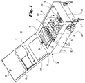
- Fig. 1 shows an outgoing or junction box 3 for a busbar trunking system for the distribution of electrical energy.
- Busbar trunking system on which the tap-off or junction box can be placed, is shown and described in DE 34 37 586 A1.
- the busbar trunking system includes a rail channel with busbars and outlets in it, on which the outgoing or shown in Figures 1 to 4 Junction box is connectable.
- the outlet or junction box 3 has contact plugs in a known manner that can be contacted at the points of departure on the conductor rails.
- the contact plug like the tap-off unit, is described in the publication is, with a disconnect contact device arranged in a disconnect contact space 6 7 electrically connected.
- the firmly connected with a first cover 1 Contact bridges bridge the isolating contact device 7 electrically only with the lid closed. This makes sense when opening of the first cover 1, the power supply to the on the outgoing or Junction box 3 connected electrical consumers interrupted is.
- the outlet or junction box 3 can be removed from the busbar trunking system without being between the contact plugs and the busbars arcing, which is sometimes very dangerous.
- a connection room 12 as can be seen in FIGS. 1 and 3, are protective and Connection elements 8, such as fuse elements 9 or terminals 10, are present, assigned to different consumers or consumer groups are.
- the securing elements 9 or terminals 10 are on top-hat rails 30 assembled.
- the tap or junction box 3 has one, according to the invention, essentially only the first cover 1 covering the isolating contact space 6 (cover surface 15) with contact bridges arranged thereon. Furthermore, the first one Cover 1 designed so that it inevitably only with the second cover 2 open or close.
- connection space 1 is separated by a second cover 2 the first cover 2 can be opened or closed in a flap-like manner, can be closed.
- the second cover 2 has a first bearing point (hinge) 4, which is connected to the basic housing 5.
- both lids are over a second bearing 11 articulated together.
- the bearing 11 is assigned to a second end face 14 of the box, as shown in FIG. 1.
- the Box 3 comprises a first end face 13 and a second opposite one End face 14.
- the first bearing 4 is assigned to the first end face 13.
- the second cover 2 has two cover surfaces for each of the rooms. With the shown The two lids are arranged one above the other in their entire length to lie.
- the top surface 15 of the first lid has the Terminal compartment 12 a window-like terminal compartment opening 17.
- the second cover 2 is either completely above the isolating contact space 6 and the connection space 12, as shown in FIG. 3, or it is only above the connection space 12 foldable, as Fig. 1 shows.
- a first bearing point 4 (hinge) to the basic housing is on the first cover 1 arranged.
- a second bearing point (hinge) 11 connects the first to the second lid 2, as shown in Figures 1 and 3.
- the bearings 4 and 11 are mutually arranged.
- the second cover 2 can with the first cover 1 opened and closed like a single lid, like a comparison of Figures 2 and 3 shows.
- the second cover 2 has a cutout 18 to lie directly above the first cover 1 in the closed state comes.
- the recess 18 lends itself to the arrangement of a handle 27.
- the handle 27 is arranged on the second cover 2.
- the Handle 27 mounted recessed in the box, the handle in one piece with an insulating body 28 is connected to hold the contact bridges 29.
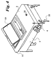
- connection terminal 12 transparent lid flap 19 for direct access to operating levers, Shift knobs and similar parts arranged.
- the first cover 1 is shown in more detail in the document EP 0 555 665 B1 and explained locking device, wherein the locking device Fastening and locking means 20 and with the fastening and locking means 20 has locking means 21 operatively connected.
- the Fastening and locking means 20 can be fastened to the rail channel
- the fastening and locking device consists, like the figures of the Document EP 0 555 665 B1 show a rotatable around its longitudinal axis Axis, which is a fastening and corresponding to the rail channel Locking element (fastening and locking means 20) and one with the corresponding locking member receives the second contact member.
- the fastening and locking device has a fastening pin for Holding the tap-off box and a locking bolt on, which is an illegal Prevention of the tap-off box on a rail channel.
- the axis is arranged on the bottom and is axially under spring action.
- the fastening and Locking device can only be operated within the tap-off unit.
- the fastening pin is provided with at least one slope.
- the locking part blocks the closing of the first cover 1 when not on the rail channel attached tap-off box.
- the locking part consists of an integrally molded Lock pin and also integrally molded and essentially handling section connected to the locking pin, the Rotational movement of the locking part is limited by a stop.
- the fastening and locking element is in FIG. 3 with the reference symbol 20 marked.
- other fasteners are on the box 3 arranged.
- Further fastening elements for rail channel fastening are marked with 22.
- the box 3 has a cable bushing 23 on one side.
- she consists essentially of metal.
- the second cover 2 or here the cover surface 16 for the connection space has second locking means 25, which are shown in Figures 1 and 2.
- the second locking means 25 can be locked on the top surface 15 of the first lid.
- the hinge-like connection of the lids to one another makes the first lid 1 coupled to the second cover 2 such that the first cover 1 is inevitably moved with the opening movement of the second cover 2.
- the first cover 1 can be removed or opened independently of the second cover 2.
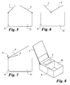
- the storage of the lids 1, 2 can, as shown in FIG. 5, independently of one another, be arranged on the end faces or, as shown in FIG. 6, in the middle. In both In individual cases, the covers only cover one of rooms 6 or 12.
- the lids 1, 2 can also be one above the other, with a coincident storage (Hinge) may be arranged, as shown in FIG. 7.
- the lid can do this forcibly opened only one after the other, but also independently, when the inner cover passes through a larger opening in the upper cover can, as shown in Fig. 8.
- the second cover 2 can only comprise a cover surface for the connection space, as shown in FIG. 8.
Abstract
Description
Die Erfindung betrifft einen Abgangs- oder Anschlußkasten nach dem Oberbegriff
des Anspruches 1.The invention relates to an outgoing or junction box according to the preamble
of
In der Druckschrift EP 0 555 665 B1 ist ein Abgangskasten gezeigt und beschrieben, der, wie dort in den Figuren 11 bis 15 gezeigt ist, zwei Deckelabschnitte aufweist, die abhängig voneinander geöffnet werden können. Der erste Deckelabschnitt steht mit einer Verriegelungsvorrichtung in Wirkverbindung. Der erste Deckelabschnitt kann nur geöffnet werden, wenn der zweite bereits offen ist. Der erste Deckelabschnitt trennt beim Öffnen automatisch die Stromzufuhr. Unterhalb des zweiten Deckelabschnitts ist eine NH-Sicherung angeordnet, die beim Öffnen des zweiten Deckels aus dem Sicherungssockel herausgezogen wird. Die genannte Schrift zeigt in der Fig. 1 einen Abgangskasten mit einem einzigen Deckel, eine Trennkontaktvorrichtung mit Trennkontaktstellen und einen Trennkontaktraum. Die Trennkontaktvorrichtung wirkt als Sicherheitsvorrichtung, die beim Arbeiten mit offenem Deckel für Spannungsfreiheit sorgt.A tap-off unit is shown and described in EP 0 555 665 B1, which, as shown there in FIGS. 11 to 15, has two cover sections which can be opened depending on each other. The first Lid section is operatively connected to a locking device. The first lid section can only be opened if the second one already is open. The first cover section automatically disconnects the power supply when opened. An NH fuse is arranged below the second cover section, pulled out of the fuse base when opening the second cover becomes. The font mentioned shows a tap-off unit in FIG. 1 with a single cover, a break contact device with break contact points and a break contact space. The isolating contact device acts as Safety device, which when working with an open lid for zero voltage provides.
Beim Öffnen des Gehäusedeckels werden bei bekannten und mit Sicherheitsvorrichtungen versehenen Abgangskästen alle angeschlossenen Verbraucher zwangsläufig vom Netz getrennt. Dies führt dazu, dass Verbraucher, die unabhängig voneinander betrieben werden müssen, wie z.B. Computer in Rechenzentren, jeweils über eigene Abgangskästen angeschlossen werden müssen.When opening the housing cover are known and with safety devices provided tap-off boxes all connected consumers necessarily disconnected from the network. This leads to consumers being independent must be operated from each other, e.g. Computers in data centers, each have to be connected via separate tap-off units.
Aufgabe der Erfindung ist es, einen Kasten nach dem Oberbegriff des Anspruches
1 zu schaffen, der sicher und ungefährlich ist und eine hohe Stromverfügbarkeit
aufweist.The object of the invention is a box according to the preamble of the
Die Aufgabe der Erfindung wird durch die kennzeichnenden Merkmale des Anspruches
1 gelöst, während in den Unteransprüchen besonders vorteilhafte Weiterbildungen
der Erfindung gekennzeichnet sind. The object of the invention is achieved by the characterizing features of the
Die Sicherheitsfunktion wird im wesentlichen dadurch erreicht, dass der Abgangs- oder Anschlußkasten einen, nur über dem Trennkontaktraum angeordneten, ersten Deckel mit daran angeordneten Kontaktbrücken aufweist. Durch die Kontaktbrücken, die in jeder Art und Weise ausgeführt werden können, solange sie die Stromzufuhr galvanisch unterbrechen, wobei die geometrische Form nicht entscheidend ist, kann an dem Abgangs- oder Anschlußkasten auch in nicht fingersicheren Bereichen gearbeitet werden. Das ist auch der Fall, wenn Klemmenblöcke oder Sicherungselemente ausgetauscht werden müssen. Vorteilhaft ist insbesondere, wenn die Trennkontaktvorrichtung mit anderen Sicherheitsfunktionen, wie einer mechanischen Verriegelungsfunktion kombinierbar ist.The safety function is essentially achieved in that the outgoing or junction box one, only located above the isolating contact space, has the first cover with contact bridges arranged thereon. By the contact bridges, which can be implemented in any way, as long as they galvanically interrupt the power supply, the geometric Form is not critical, can be on the tap or junction box also work in areas that are not finger-safe. That is also the one Case when terminal blocks or fuse elements are replaced have to. It is particularly advantageous if the isolating contact device is used other safety functions, such as a mechanical locking function can be combined.
Dabei ist es von untergeordneter Bedeutung, ob Kontaktbrücken an einem Deckel oder andere die Stromzufuhr trennende Mittel an einem Deckel angeordnet sind.It is of secondary importance whether contact bridges on one Lid or other means separating the power supply arranged on a lid are.
Durch die Anordnung von zwei Deckeln erfolgt grundsätzlich eine Einteilung in einem Trennkontaktraum und einen Anschlussraum. Wenn der Anschlussraum mit einem zweiten Deckel verschließbar ist, der unabhängig von einem ersten Deckel zu öffnen ist, kann dennoch, ohne zwangsläufige Betätigung der Trennkontaktvorrichtung, in dem Anschlussraum gearbeitet werden.By arranging two lids, there is basically a division into an isolating contact space and a connection space. If the connection space can be closed with a second lid, which is independent of a first one The lid can still be opened without inevitable actuation of the Disconnect contact device in which connection space is worked.
Besonders sicher wird der Abgangs- oder Anschlußkasten erst dadurch, wenn der Anschlussraum nur für Schutz- und Anschlusselemente nach Schutzart IP20 (fingersicher) vorgesehen ist.The tap-off or junction box only becomes particularly secure when the connection compartment only for protection and connection elements according to the degree of protection IP20 (finger safe) is provided.
Günstig für die Montage des zweiten Deckels und einfach ausgestaltbar ist er, wenn er klappenförmig angelenkt und zu öffnen ist.It is favorable for the assembly of the second cover and is easy to design, if it is hinged and openable.
Eine besonders handhabungsfreundliche, sichere und einfach herstellbare Ausführungsform ergibt sich, wenn der zweite Deckel eine erste Lagerstelle umfasst, die mit dem Grundgehäuse verbunden ist, und der zweite Deckel eine zweite Lagerstelle umfasst, die einer zweiten Stirnseite des Abgangs- oder Anschlusskastens zugeordnet ist, wenn die erste Lagerstelle einer ersten - der zweiten Stirnseite gegenüberliegenden - Stirnseite zugeordnet ist, wodurch sich zwei unterschiedliche Öffnungs- bzw. Drehrichtungen ergeben.A particularly easy to use, safe and easy to manufacture embodiment results if the second cover comprises a first bearing point, which is connected to the basic housing, and the second cover a second Bearing includes a second end of the tap or junction box is assigned if the first bearing of a first - the second Face opposite - face is assigned, creating two different Opening or rotation directions result.
Jeder Deckel kann mit zwei Deckflächen zur Auflage auf dem Anschlussraum und auf dem Trennkontaktraum ausgebildet sein.Each cover can have two cover surfaces to rest on the connection compartment and be formed on the isolating contact space.
Die Deckfläche auf dem Anschlussraum des ersten Deckels kann fensterartig aufgebrochen sein. Der zweite Deckel kann mit dem ersten Deckel über eine zweite Lagerstelle derart verbunden sein, dass der zweite Deckel entweder vollständig über dem Trennkontaktraum und dem Anschlussraum oder nur über dem Anschlussraum aufliegt und aufklappbar ist.The cover surface on the connection space of the first cover can be window-like to have left The second cover can be connected to the first cover via a second bearing so that the second cover either completely above the isolating contact space and the connection space or only rests above the connection compartment and can be opened.
Durch diese Kombinationslösung gelingt es, mit wenig Aufwand einerseits eine vormontierbare Deckel-Einheit zu schaffen und andererseits eine störlichtbogengerechte Lösung zu bieten.This combination solution makes it possible to do one with little effort to create preassembled cover unit and, on the other hand, an arcing-compliant To offer a solution.
Günstig ist eine Konstruktion, wenn die Trennfunktion und mögliche Verriegelungsfunktionen mit dem Öffnen des zweiten Deckels ausgelöst werden, was besonders handhabungsfreundlich ist.A construction is favorable if the separation function and possible locking functions what with the opening of the second lid triggered is particularly easy to use.
Eine weitere besonders vorteilhafte Ausgestaltung ergibt sich, wenn der zweite Deckel eine Aussparung aufweist, die einen Durchgriff auf den ersten Deckel erlaubt. Damit werden bedarfsweise ein Griff, Arretierungsmittel oder weitere nicht näher beschriebene Teile von außen auch bei geschlossenem zweiten Deckel zugänglich.Another particularly advantageous embodiment results when the second Cover has a recess which has a passage through the first cover allowed. Thus, a handle, locking means or others are required Parts not described in detail from the outside even when the second cover is closed accessible.
Um einen direkten Zugang zu Sicherungselementen, wie Schaltautomaten, Leitungsschutzschaltem, Leistungsschaltern, Motorschutzschaltern, Schmelzsicherungen oder dergleichen zu ermöglichen und ein Wiedereinschalten der Schaltgeräte, bzw. ein Austauschen von Sicherungen ohne den zweiten Deckel öffnen zu müssen, erweist es sich als vorteilhaft, dass oberhalb des Anschlussraumes eine Deckelklappe angeordnet ist. In order to have direct access to fuse elements such as automatic switchgear, circuit breakers, Circuit breakers, motor protection switches, fuses or the like and to switch the switching devices on again, or replace a fuse without opening the second cover , it proves to be advantageous that above the connection space a lid flap is arranged.
Der Schaltzustand der Geräte ist von außen sichtbar, wenn die Deckelklappe transparent ist.The switching status of the devices is visible from the outside when the cover flap is transparent.
Vorteilhaft kann es sein, wenn der erste Deckel derart ausgeführt ist, dass er zwangsläufig mit dem zweiten Deckel zu öffnen ist, so dass die Anschlusselemente im Anschlussraum in jedem Fall spannungsfrei gemacht werden.It can be advantageous if the first cover is designed such that it must be opened with the second cover, so that the connection elements be de-energized in the terminal compartment in any case.
Ein unzulässiges Aufsetzen oder Abnehmen des Abgangs- oder Anschlusskastens auf dem Schienenkanal wird verhindert, wenn der erste Deckel mit einer Verriegelungseinrichtung versehen ist, die Befestigungs- und Verriegelungsmittel und mit den Befestigungs- und Verriegelungsmittel wirkverbundenen Sperrmittel umfasst, wobei die Befestigungs- und Verriegelungsmittel an dem Schienenkanal befestigbar sind.An impermissible installation or removal of the tap-off or connection box on the rail channel is prevented if the first cover with a Locking device is provided, the fastening and locking means and locking means operatively connected to the fastening and locking means comprises, wherein the fastening and locking means on the rail channel are attachable.
Die Fixierung des Abgangs- oder Anschlusskastens wird verbessert, wenn der Abgangs- oder Anschlußkasten Befestigungselemente umfasst, wobei die Befestigungselemente an dem Schienenkanal befestigbar sind.The fixation of the tap-off or junction box is improved if the Outlet or junction box includes fasteners, the fasteners are attachable to the rail channel.
Der Abgangs- oder Anschlußkasten hat mindestens eine Kabeldurchführung, vorzugsweise jedoch nur an einer Seite.The tap or junction box has at least one cable entry, but preferably only on one side.
Ein sicherer Verschluss des Trennkontaktraums ergibt sich, wenn der erste Deckel erste Arretierungsmittel umfasst und/oder die ersten Arretierungsmittel an dem Grundgehäuse an mindestens einer Gegenarretierung arretierbar sind.The isolating contact space is securely closed when the first cover comprises first locking means and / or the first locking means the basic housing can be locked on at least one counter-lock.
Ein sicherer Verschluss des Anschlussraums ergibt sich, wenn der zweite Deckel zweite Arretierungsmittel aufweist, wobei in günstiger Weise die zweiten Arretierungsmittel am ersten Deckel und/oder am Grundgehäuse arretierbar sein können.The connection compartment is securely closed when the second cover is closed has second locking means, the second locking means in a favorable manner can be locked on the first cover and / or on the basic housing.
Ebenso ist es für die Handhabung günstig, wenn mindestens einer der Deckel mit einem Griff versehen ist. It is also convenient for handling if at least one of the lids is provided with a handle.
Formschön ist es, dass der Griff im Abgangs- oder Anschlußkasten eingesenkt angeordnet ist.It is elegant that the handle is recessed in the tap or junction box is arranged.
Kostensparend ist es, wenn der Griff einstückig mit einem Isolierkörper zur Halterung der Kontaktbrücken ausgeführt istIt is cost-saving if the handle is made in one piece with an insulating body for mounting the contact bridges are executed
Die Deckel haben primär die Funktion der Einzel-Abdeckung der jeweiligen Anschlussräume. Wobei die Deckel jedoch auch mit Deckflächen für beide Anschlussräume ausgebildet sein können, so dass sie über jeweils beiden Räumen aufliegen können. Weiterhin hat mindestens der erste Deckel die Funktion der Spannungstrennung beim Öffnen. Diese Funktionen der Deckel können untereinander sinnvoll kombiniert sein. Eine vorteilhafte Ausgestaltung ergibt sich, wenn der erste Deckel so mit dem zweiten Deckel scharnierartig verbunden ist, dass beide Deckel zwei übereinander angeordnete Lagen bilden.The covers have primarily the function of the individual cover of the respective Connecting rooms. However, the lids also have cover surfaces for both Terminal spaces can be formed so that they are above both Rooms. Furthermore, at least the first cover has the Function of voltage isolation when opening. This functions the lid can be meaningfully combined with each other. An advantageous embodiment results when the first cover is hinge-like with the second cover is connected that both covers form two layers arranged one above the other.
Anhand der Zeichnung, in der fünf Ausführungsbeispiele dargestellt sind, sollen die Erfindung, die Ausgestaltungen und Verbesserungen der Erfindung und weitere Vorteile näher beschrieben und erläutert werden.Based on the drawing, in which five exemplary embodiments are shown the invention, the refinements and improvements of the invention and others Advantages are described and explained in more detail.
Es zeigen:
- Fig. 1
- eine perspektivische Darstellung des Abgangs- oder Anschlusskastens mit geöffnetem zweiten Deckel,
- Fig. 2
- eine perspektivische Darstellung des Abgangs- oder Anschlusskastens mit geschlossenem zweiten Deckel,
- Fig. 3
- eine perspektivische Darstellung des Abgangs- oder Anschlusskastens mit geöffnetem ersten und zweiten Deckel,
- Fig. 4
- eine perspektivische Darstellung des Abgangs- oder Anschlusskastens mit geöffneter Deckelklappe,
- Fig. 5
- eine Prinzipdarstellung einer zweiten Ausführungsform des erfindungsgemäßen Abgangs- oder Anschlusskastens,
- Fig. 6
- eine Prinzipdarstellung einer dritten Ausführungsform des erfindungsgemäßen Abgangs- oder Anschlusskastens,
- Fig. 7
- eine Prinzipdarstellung einer vierten Ausführungsform des erfindungsgemäßen Abgangs- oder Anschlusskastens und
- Fig. 8
- eine Prinzipdarstellung einer fünften Ausführungsform des erfindungsgemäßen Abgangs- oder Anschlusskastens.
- Fig. 1
- a perspective view of the tap or junction box with the second cover open,
- Fig. 2
- a perspective view of the tap or junction box with closed second cover,
- Fig. 3
- 1 shows a perspective view of the tap-off or connection box with the first and second covers open,
- Fig. 4
- a perspective view of the tap-off or connection box with the lid flap open,
- Fig. 5
- a schematic diagram of a second embodiment of the tap-off or connection box according to the invention,
- Fig. 6
- a schematic diagram of a third embodiment of the tap-off or connection box according to the invention,
- Fig. 7
- a schematic diagram of a fourth embodiment of the tap or junction box according to the invention and
- Fig. 8
- a schematic diagram of a fifth embodiment of the tap-off or connection box according to the invention.
Die Fig. 1 zeigt einen Abgangs- oder Anschlußkasten 3 für einen Schienenverteiler
zur Verteilung elektrischer Energie. Der hier nicht näher dargestellte
Schienenverteiler, auf dem der Abgangs- oder Anschlußkasten aufsetzbar ist,
ist in der DE 34 37 586 A1 gezeigt und beschrieben. Der Schienenverteiler
umfasst einen Schienenkanal mit darin geführten Stromschienen und Abgangsstellen,
an denen der in den Figuren 1 bis 4 dargestellte Abgangs- oder
Anschlußkasten anschließbar ist.Fig. 1 shows an outgoing or
Der Abgangs- oder Anschlußkasten 3 weist Kontaktstecker in bekannter Weise
auf, die an den Abgangsstellen an den Stromschienen kontaktierbar sind. Der
Kontaktstecker ist, wie auch der Abgangskasten, der in der Druckschrift beschrieben
ist, mit einer in einem Trennkontaktraum 6 angeordneten Trennkontaktvorrichtung
7 elektrisch verbunden. Die mit einem ersten Deckel 1 fest verbundenen
Kontaktbrücken überbrücken die Trennkontaktvorrichtung 7 elektrisch
nur bei geschlossenem Deckel. Dies hat denn Sinn, dass beim Öffnen
des ersten Deckels 1 die Stromzufuhr zu den an dem Abgangs- oder
Anschlußkasten 3 angeschlossenen elektrischen Verbrauchern unterbrochen
ist. Der Abgangs- oder Anschlußkasten 3 kann vom Schienenverteiler abmontiert
werden, ohne dass zwischen den Kontaktsteckern und den Stromschienen
eine zum Teil sehr gefährliche Lichtbogenbildung entsteht. In einem Anschlussraum
12 sind, wie in den Figuren 1 und 3 zu sehen ist, Schutz- und
Anschlusselemente 8, wie Sicherungselemente 9 oder Klemmen 10, vorhanden,
die verschiedenen Verbrauchern oder Verbrauchergruppen zugeordnet
sind. Die Sicherungselemente 9 oder Klemmen 10 werden auf Hutschienen 30
montiert.The outlet or
Der Abgangs- oder Anschlußkasten 3 weist erfindungsgemäß einen, im wesentlichen
nur den Trennkontaktraum 6 abdeckenden ersten Deckel 1 (Deckfläche
15) mit daran angeordneten Kontaktbrücken auf. Weiterhin ist der erste
Deckel 1 so ausgeführt, dass er zwangsläufig nur mit dem zweiten Deckel 2 zu
öffnen oder zu schließen ist.The tap or
Der Anschlussraum 1 ist durch einen zweiten Deckel 2, der unabhängig von
dem ersten Deckel 2 klappenförmig zu öffnen bzw. zu schließen ist, verschließbar.
Der zweite Deckel 2 weist eine erste Lagerstelle (Scharnier) 4 auf,
die mit dem Grundgehäuse 5 verbunden ist. Zusätzlich sind beide Deckel über
eine zweite Lagerstelle 11 miteinander gelenkig verbunden. Die Lagerstelle 11 ist
einer zweiten Stirnseite 14 des Kastens zugeordnet, wie die Figur 1 zeigt. Der
Kasten 3 umfasst eine erste Stirnseite 13 und eine zweite gegenüberliegende
Stirnseite 14. Die erste Lagerstelle 4 ist der ersten Stirnseite 13 zugeordnet. Der
zweite Deckel 2 weist zwei Deckflächen für jeden den Räumen auf. Mit der gezeigten
Anordnung kommen beide Deckel in ihrer gesamten Länge übereinander
zu liegen. Vorzugsweise hat die Deckfläche 15 des ersten Deckels über dem
Anschlussraum 12 eine fensterartige Anschlussraumöffnung 17. Der zweite Deckel
2 liegt entweder vollständig über dem Trennkontaktraum 6 und dem Anschlussraum
12, wie Fig. 3 zeigt, oder er ist nur über dem Anschlussraum 12
aufklappbar, wie Fig. 1 zeigt.The
Eine erste Lagerstelle 4 (Scharnier) zum Grundgehäuse ist am ersten Deckel 1
angeordnet. Eine zweite Lagerstelle (Scharnier) 11 verbindet den ersten mit dem
zweiten Deckel 2, wie in den Figuren 1 und 3 gezeigt ist. Die Lagerstellen 4 und
11 sind wechselseitig angeordnet. Der zweite Deckel 2 kann mit dem ersten Deckel
1 wie ein einziger Deckel geöffnet und geschlossen werden, wie ein Vergleich
der Figuren 2 und 3 zeigt.A first bearing point 4 (hinge) to the basic housing is on the
Erfindungsgemäß sind in dem Anschlussraum 12 nur fingersichere Schutz- und
Anschlusselemente 8 vorhanden. Ein Öffnen des zweiten Deckels 2, beispielsweise
zu Kontrollzwecken, ist ohne Unterbrechung der Stromversorgung
für z.B. Rechenanlagen möglich. Eine Berührung spannungsführender Teile ist
mit geöffnetem zweiten Deckel nicht möglich. According to the invention, there are only finger-safe protections and
Der zweite Deckel 2 weist, wie in der Fig. 1 zu sehen ist, eine Aussparung 18
auf, die im geschlossenen Zustand direkt über dem ersten Deckel 1 zu liegen
kommt.As can be seen in FIG. 1, the
Die Aussparung 18 bietet sich für die Anordnung eines Griffes 27 an. Der Griff 27
ist an dem zweiten Deckel 2 angeordnet. In dieser Ausführungsform wird der
Griff 27 im Kasten eingesenkt montiert, wobei der Griff einstückig mit einem Isolierkörper
28 zur Halterung der Kontaktbrücken 29 verbunden ist.The
Über dem Anschlussraum 12 ist, wie in den Figuren 2 und 4 dargestellt ist, eine
transparente Deckelklappe 19 für den direkten Zugang zu Betätigungshebeln,
Schaltknebeln und ähnlichen Teilen angeordnet.As shown in FIGS. 2 and 4, there is a
Der erste Deckel 1 ist mit einer in dem Dokument EP 0 555 665 B1 näher gezeigten
und erläuterten Verriegelungseinrichtung versehen, wobei die Verriegelungseinrichtung
Befestigungs- und Verriegelungsmittel 20 und mit den Befestigungs-
und Verriegelungsmittel 20 wirkverbundenen Sperrmittel 21 aufweist. Die
Befestigungs- und Verriegelungsmittel 20 sind an dem Schienenkanal befestigbarThe
Die Befestigungs- und Verriegelungsvorrichtung besteht, wie die Figuren des
Dokuments EP 0 555 665 B1 zeigen, aus einer um ihre Längsachse drehbaren
Achse, die ein mit dem Schienenkanal korrespondierendes Befestigungs- und
Verriegelungselement (Befestigungs- und Verriegelungsmittel 20) und ein mit
dem zweiten Kontaktorgan korrespondierendes Sperrteil aufnimmt. Die Befestigungs-
und Verriegelungsvorrichtung weist einen Befestigungszapfen zum
Halten des Abgangskastens und einen Sperr-Riegel auf, der ein unzulässiges
Aufsetzen des Abgangskastens auf einen Schienenkanal verhindert. Die Achse
ist bodenseitig angeordnet und steht axial unter Federwirkung. Die Befestigungsund
Verriegelungsvorrichtung ist nur innerhalb des Abgangskastens betätigbar.
Der Befestigungszapfen ist mit mindestens einer Steigung versehen. Das Sperrteil
blockiert das Schließen des ersten Deckels 1 bei nicht auf dem Schienenkanal
befestigtem Abgangskasten. Das Sperrteil besteht aus einem einstückig angeformten
Sperrstift und einem ebenfalls einstückig angeformten und im wesentlichen
mit dem Sperrstift verbundenen Handhabungsabschnitt, wobei die
Drehbewegung des Sperrteiles durch einen Anschlag begrenzt wird.The fastening and locking device consists, like the figures of the
Document EP 0 555 665 B1 show a rotatable around its longitudinal axis
Axis, which is a fastening and corresponding to the rail channel
Locking element (fastening and locking means 20) and one with
the corresponding locking member receives the second contact member. The fastening
and locking device has a fastening pin for
Holding the tap-off box and a locking bolt on, which is an illegal
Prevention of the tap-off box on a rail channel. The axis
is arranged on the bottom and is axially under spring action. The fastening and
Locking device can only be operated within the tap-off unit.
The fastening pin is provided with at least one slope. The locking part
blocks the closing of the
Das Befestigungs- und Verriegelungselement ist in Fig. 3 mit dem Bezugszeichen
20 gekennzeichnet. Zusätzlich sind weitere Befestigungselemente an
dem Kasten 3 angeordnet. Weitere Befestigungselemente zur Schienenkanalbefestigung
sind mit 22 gekennzeichnet.The fastening and locking element is in FIG. 3 with the
Der Kasten 3 weist an einer Seite eine Kabeldurchführung 23 auf. Sie besteht
im wesentlichen aus Metall.The
Wie aus den Figuren 1 und 2 zu entnehmen ist, ist der erste Deckel 1 mit ersten
Arretierungsmittel 24 versehen. Diese Arretierungsmittel 24 wirken mit einer
Gegenarretierung 26 am Grundgehäuse 5 zusammen, die Fig. 3 zeigt.As can be seen from Figures 1 and 2, the
Der zweite Deckel 2 bzw. hier die Deckfläche 16 für den Anschlussraum weist
zweite Arretierungsmittel 25 auf, die in den Figuren 1 und 2 abgebildet sind. Die
zweiten Arretierungsmittel 25 sind an der Deckfläche 15 des ersten Deckels arretierbar.The
Durch die schamierartige Verbindung der Deckel miteinander wird der erste Deckel
1 mit dem zweiten Deckel 2 derart gekoppelt, dass der erste Deckel 1
zwangsläufig mit der Öffnungsbewegung des zweiten Deckels 2 bewegt wird.The hinge-like connection of the lids to one another makes the
In einer weiteren, in Fig. 5 gezeigten Ausführungsform ist der erste Deckel 1
unabhängig von dem zweiten Deckel 2 entfernbar bzw. zu öffnen.In a further embodiment shown in FIG. 5, the
Die vorliegende Erfindung ist nicht auf die vorstehend beschriebenen Ausführungsformen beschränkt, sondern umfasst auch alle im Sinne der Erfindung gleichwirkenden Ausführungsformen. So lässt sich die Erfindung beispielsweise durch weitere Ausführungsformen, die in den Figuren 5 bis 7 prinzipiell dargestellt sind, realisieren. The present invention is not limited to the above-described embodiments limited, but also includes all within the meaning of the invention equivalent embodiments. For example, the invention can be by further embodiments, which in principle in Figures 5 to 7 are shown, realize.
Die Lagerung der Deckel 1, 2 kann, wie Fig. 5 zeigt, unabhängig voneinander,
an den Stirnseiten oder, wie Fig. 6 zeigt, in der Mitte angeordnet sein. In beiden
Fällen decken die Deckel einzeln nur einen der Räume 6 oder 12 ab.The storage of the
Die Deckel 1,2 können auch übereinander, mit einer zusammenfallenden Lagerung
(Scharnier) angeordnet sein, wie Fig. 7 zeigt. Die Deckel können hierbei
zwangsweise nur nacheinander geöffnet werden, aber auch unabhängig,
wenn der innere Deckel durch eine größere Öffnung im oberen Deckel hindurchtreten
kann, wie in Fig. 8 gezeigt. Der zweite Deckel 2 kann auch nur
eine Deckfläche für den Anschlussraum umfassen, wie die Fig. 8 zeigt.The
Ferner gehören auch alle in der Zeichnung gezeigten Merkmale und die hier beschriebenen zur Erfindung. Furthermore, all the features shown in the drawing and those included here described to the invention.
Claims (14)
Applications Claiming Priority (2)
| Application Number | Priority Date | Filing Date | Title |
|---|---|---|---|
| DE10065088 | 2000-12-23 | ||
| DE10065088A DE10065088B4 (en) | 2000-12-23 | 2000-12-23 | Tap or junction box |
Publications (3)
| Publication Number | Publication Date |
|---|---|
| EP1220406A2 true EP1220406A2 (en) | 2002-07-03 |
| EP1220406A3 EP1220406A3 (en) | 2002-10-16 |
| EP1220406B1 EP1220406B1 (en) | 2005-12-21 |
Family
ID=7669039
Family Applications (1)
| Application Number | Title | Priority Date | Filing Date |
|---|---|---|---|
| EP01124200A Expired - Lifetime EP1220406B1 (en) | 2000-12-23 | 2001-10-11 | Outlet or junction box |
Country Status (5)
| Country | Link |
|---|---|
| EP (1) | EP1220406B1 (en) |
| AT (1) | ATE313868T1 (en) |
| DE (2) | DE10065088B4 (en) |
| DK (1) | DK1220406T3 (en) |
| ES (1) | ES2255531T3 (en) |
Cited By (3)
| Publication number | Priority date | Publication date | Assignee | Title |
|---|---|---|---|---|
| CN101783490A (en) * | 2008-11-14 | 2010-07-21 | 华鹏集团有限公司 | Manual operating mechanism of jack box |
| CN103579977A (en) * | 2013-11-05 | 2014-02-12 | 江苏威腾母线有限公司 | Interlocking mechanism of jack box of bus duct |
| CN107147022A (en) * | 2017-05-12 | 2017-09-08 | 许继集团有限公司 | A kind of secondary device device |
Families Citing this family (1)
| Publication number | Priority date | Publication date | Assignee | Title |
|---|---|---|---|---|
| DE102021103880A1 (en) | 2021-02-18 | 2022-08-18 | Metz Connect Tech Gmbh | wall distribution box |
Citations (2)
| Publication number | Priority date | Publication date | Assignee | Title |
|---|---|---|---|---|
| US3335329A (en) * | 1965-07-02 | 1967-08-08 | Gen Electric | Fusible busway plug structure with movable plug carrier member |
| EP0555665A1 (en) * | 1992-02-13 | 1993-08-18 | Moeller GmbH | Outlet box, especially for busways |
Family Cites Families (1)
| Publication number | Priority date | Publication date | Assignee | Title |
|---|---|---|---|---|
| DE3437586A1 (en) * | 1984-10-13 | 1986-04-24 | Klöckner-Moeller Elektrizitäts GmbH, 5300 Bonn | Busbar distributor |
-
2000
- 2000-12-23 DE DE10065088A patent/DE10065088B4/en not_active Expired - Fee Related
-
2001
- 2001-10-11 DE DE50108451T patent/DE50108451D1/en not_active Expired - Lifetime
- 2001-10-11 DK DK01124200T patent/DK1220406T3/en active
- 2001-10-11 EP EP01124200A patent/EP1220406B1/en not_active Expired - Lifetime
- 2001-10-11 ES ES01124200T patent/ES2255531T3/en not_active Expired - Lifetime
- 2001-10-11 AT AT01124200T patent/ATE313868T1/en not_active IP Right Cessation
Patent Citations (2)
| Publication number | Priority date | Publication date | Assignee | Title |
|---|---|---|---|---|
| US3335329A (en) * | 1965-07-02 | 1967-08-08 | Gen Electric | Fusible busway plug structure with movable plug carrier member |
| EP0555665A1 (en) * | 1992-02-13 | 1993-08-18 | Moeller GmbH | Outlet box, especially for busways |
Cited By (5)
| Publication number | Priority date | Publication date | Assignee | Title |
|---|---|---|---|---|
| CN101783490A (en) * | 2008-11-14 | 2010-07-21 | 华鹏集团有限公司 | Manual operating mechanism of jack box |
| CN101783490B (en) * | 2008-11-14 | 2013-09-18 | 江苏华鹏智能电气股份有限公司 | Manual operating mechanism of jack box |
| CN103579977A (en) * | 2013-11-05 | 2014-02-12 | 江苏威腾母线有限公司 | Interlocking mechanism of jack box of bus duct |
| CN103579977B (en) * | 2013-11-05 | 2016-10-05 | 江苏威腾母线有限公司 | A kind of busway inserting case interlocking gear |
| CN107147022A (en) * | 2017-05-12 | 2017-09-08 | 许继集团有限公司 | A kind of secondary device device |
Also Published As
| Publication number | Publication date |
|---|---|
| EP1220406A3 (en) | 2002-10-16 |
| DE10065088A1 (en) | 2002-07-18 |
| ATE313868T1 (en) | 2006-01-15 |
| DK1220406T3 (en) | 2006-05-08 |
| EP1220406B1 (en) | 2005-12-21 |
| ES2255531T3 (en) | 2006-07-01 |
| DE10065088B4 (en) | 2004-02-05 |
| DE50108451D1 (en) | 2006-01-26 |
Similar Documents
| Publication | Publication Date | Title |
|---|---|---|
| DE10160090B4 (en) | Fuse holder | |
| EP1482530B1 (en) | Fuse box for a vehicle | |
| DE102019212980A1 (en) | Electric machine with a high-voltage connection arrangement and a safety locking device | |
| EP2154701B1 (en) | Installation device with protective device | |
| EP1220406B1 (en) | Outlet or junction box | |
| DE10115777A1 (en) | Multi-pole switching device for use on busbar systems | |
| EP0555665B1 (en) | Outlet box, especially for busways | |
| EP1787358B1 (en) | Power feed module with cage clamp terminals | |
| EP1045414B1 (en) | Load break switch with low-voltage high-power fuses | |
| DE10131739B4 (en) | Power converter | |
| EP0857367B1 (en) | Contact-separating device for a tap-off box of a power-distribution system | |
| DE2937671C2 (en) | Firedamp or explosion-proof connection device | |
| DE3220839A1 (en) | Explosionproof or flameproof plug device | |
| EP1296431A2 (en) | Bus bar assembly | |
| DE102015104873A1 (en) | Locking system for a shutter that separates a busbar section from an electrical component section of an electrical enclosure | |
| DE102010001411B4 (en) | Housing for an electrical circuit | |
| EP0890970B1 (en) | Cover for contacts for fuses in devices with low voltage high power fuses | |
| EP0890971B1 (en) | Cover for contacts for fuses in devices with low voltage high power fuses | |
| DE202019001525U1 (en) | Electric switch | |
| DE4204238C2 (en) | Insert with a switchable NH fuse strip for insert distributors | |
| EP1638123A1 (en) | Protective switch with slidable contact-plug | |
| DE102017202135A1 (en) | Systems and methods for locking a circuit breaker | |
| EP3358687B1 (en) | Partitioning device for a distribution cabinet and distribution cabinet comprising such a partitioning device | |
| DE2800277A1 (en) | Connection panel for incoming telephone cables - has lugs on side walls to hold insulating piece facing circuit breaker contacts | |
| EP0895663B1 (en) | Tap-off unit, especially for busbar trunking systems |
Legal Events
| Date | Code | Title | Description |
|---|---|---|---|
| PUAI | Public reference made under article 153(3) epc to a published international application that has entered the european phase |
Free format text: ORIGINAL CODE: 0009012 |
|
| AK | Designated contracting states |
Kind code of ref document: A2 Designated state(s): AT BE CH CY DE DK ES FI FR GB GR IE IT LI LU MC NL PT SE TR |
|
| AX | Request for extension of the european patent |
Free format text: AL;LT;LV;MK;RO;SI |
|
| PUAL | Search report despatched |
Free format text: ORIGINAL CODE: 0009013 |
|
| RIC1 | Information provided on ipc code assigned before grant |
Free format text: 7H 02G 5/08 A, 7H 02B 1/48 B |
|
| AK | Designated contracting states |
Kind code of ref document: A3 Designated state(s): AT BE CH CY DE DK ES FI FR GB GR IE IT LI LU MC NL PT SE TR |
|
| AX | Request for extension of the european patent |
Free format text: AL;LT;LV;MK;RO;SI |
|
| 17P | Request for examination filed |
Effective date: 20020905 |
|
| AKX | Designation fees paid |
Designated state(s): AT BE CH CY DE DK ES FI FR GB GR IE IT LI LU MC NL PT SE TR |
|
| 17Q | First examination report despatched |
Effective date: 20040706 |
|
| RAP1 | Party data changed (applicant data changed or rights of an application transferred) |
Owner name: SIEMENS AKTIENGESELLSCHAFT |
|
| GRAP | Despatch of communication of intention to grant a patent |
Free format text: ORIGINAL CODE: EPIDOSNIGR1 |
|
| GRAS | Grant fee paid |
Free format text: ORIGINAL CODE: EPIDOSNIGR3 |
|
| GRAA | (expected) grant |
Free format text: ORIGINAL CODE: 0009210 |
|
| AK | Designated contracting states |
Kind code of ref document: B1 Designated state(s): AT BE CH CY DE DK ES FI FR GB GR IE IT LI LU MC NL PT SE TR |
|
| PG25 | Lapsed in a contracting state [announced via postgrant information from national office to epo] |
Ref country code: IT Free format text: LAPSE BECAUSE OF FAILURE TO SUBMIT A TRANSLATION OF THE DESCRIPTION OR TO PAY THE FEE WITHIN THE PRESCRIBED TIME-LIMIT;WARNING: LAPSES OF ITALIAN PATENTS WITH EFFECTIVE DATE BEFORE 2007 MAY HAVE OCCURRED AT ANY TIME BEFORE 2007. THE CORRECT EFFECTIVE DATE MAY BE DIFFERENT FROM THE ONE RECORDED. Effective date: 20051221 Ref country code: IE Free format text: LAPSE BECAUSE OF FAILURE TO SUBMIT A TRANSLATION OF THE DESCRIPTION OR TO PAY THE FEE WITHIN THE PRESCRIBED TIME-LIMIT Effective date: 20051221 Ref country code: FI Free format text: LAPSE BECAUSE OF FAILURE TO SUBMIT A TRANSLATION OF THE DESCRIPTION OR TO PAY THE FEE WITHIN THE PRESCRIBED TIME-LIMIT Effective date: 20051221 |
|
| REG | Reference to a national code |
Ref country code: GB Ref legal event code: FG4D Free format text: NOT ENGLISH |
|
| REG | Reference to a national code |
Ref country code: CH Ref legal event code: EP |
|
| REG | Reference to a national code |
Ref country code: IE Ref legal event code: FG4D Free format text: LANGUAGE OF EP DOCUMENT: GERMAN |
|
| REF | Corresponds to: |
Ref document number: 50108451 Country of ref document: DE Date of ref document: 20060126 Kind code of ref document: P |
|
| REG | Reference to a national code |
Ref country code: CH Ref legal event code: NV Representative=s name: SIEMENS SCHWEIZ AG |
|
| PG25 | Lapsed in a contracting state [announced via postgrant information from national office to epo] |
Ref country code: GR Free format text: LAPSE BECAUSE OF FAILURE TO SUBMIT A TRANSLATION OF THE DESCRIPTION OR TO PAY THE FEE WITHIN THE PRESCRIBED TIME-LIMIT Effective date: 20060321 |
|
| REG | Reference to a national code |
Ref country code: SE Ref legal event code: TRGR |
|
| GBT | Gb: translation of ep patent filed (gb section 77(6)(a)/1977) |
Effective date: 20060328 |
|
| REG | Reference to a national code |
Ref country code: DK Ref legal event code: T3 |
|
| PG25 | Lapsed in a contracting state [announced via postgrant information from national office to epo] |
Ref country code: PT Free format text: LAPSE BECAUSE OF FAILURE TO SUBMIT A TRANSLATION OF THE DESCRIPTION OR TO PAY THE FEE WITHIN THE PRESCRIBED TIME-LIMIT Effective date: 20060522 |
|
| REG | Reference to a national code |
Ref country code: ES Ref legal event code: FG2A Ref document number: 2255531 Country of ref document: ES Kind code of ref document: T3 |
|
| REG | Reference to a national code |
Ref country code: IE Ref legal event code: FD4D |
|
| ET | Fr: translation filed | ||
| PLBE | No opposition filed within time limit |
Free format text: ORIGINAL CODE: 0009261 |
|
| STAA | Information on the status of an ep patent application or granted ep patent |
Free format text: STATUS: NO OPPOSITION FILED WITHIN TIME LIMIT |
|
| PG25 | Lapsed in a contracting state [announced via postgrant information from national office to epo] |
Ref country code: MC Free format text: LAPSE BECAUSE OF NON-PAYMENT OF DUE FEES Effective date: 20061031 |
|
| 26N | No opposition filed |
Effective date: 20060922 |
|
| PG25 | Lapsed in a contracting state [announced via postgrant information from national office to epo] |
Ref country code: CY Free format text: LAPSE BECAUSE OF FAILURE TO SUBMIT A TRANSLATION OF THE DESCRIPTION OR TO PAY THE FEE WITHIN THE PRESCRIBED TIME-LIMIT Effective date: 20051221 |
|
| PGFP | Annual fee paid to national office [announced via postgrant information from national office to epo] |
Ref country code: NL Payment date: 20081017 Year of fee payment: 8 |
|
| PGFP | Annual fee paid to national office [announced via postgrant information from national office to epo] |
Ref country code: DK Payment date: 20081016 Year of fee payment: 8 Ref country code: LU Payment date: 20081021 Year of fee payment: 8 |
|
| PGFP | Annual fee paid to national office [announced via postgrant information from national office to epo] |
Ref country code: AT Payment date: 20080910 Year of fee payment: 8 Ref country code: ES Payment date: 20081112 Year of fee payment: 8 |
|
| PGFP | Annual fee paid to national office [announced via postgrant information from national office to epo] |
Ref country code: BE Payment date: 20081030 Year of fee payment: 8 Ref country code: SE Payment date: 20081016 Year of fee payment: 8 |
|
| REG | Reference to a national code |
Ref country code: CH Ref legal event code: PCAR Free format text: SIEMENS SCHWEIZ AG;INTELLECTUAL PROPERTY FREILAGERSTRASSE 40;8047 ZUERICH (CH) |
|
| PGFP | Annual fee paid to national office [announced via postgrant information from national office to epo] |
Ref country code: CH Payment date: 20090114 Year of fee payment: 8 |
|
| BERE | Be: lapsed |
Owner name: *SIEMENS A.G. Effective date: 20091031 |
|
| REG | Reference to a national code |
Ref country code: NL Ref legal event code: V1 Effective date: 20100501 |
|
| REG | Reference to a national code |
Ref country code: CH Ref legal event code: PL |
|
| EUG | Se: european patent has lapsed | ||
| REG | Reference to a national code |
Ref country code: DK Ref legal event code: EBP |
|
| PG25 | Lapsed in a contracting state [announced via postgrant information from national office to epo] |
Ref country code: NL Free format text: LAPSE BECAUSE OF NON-PAYMENT OF DUE FEES Effective date: 20100501 |
|
| PG25 | Lapsed in a contracting state [announced via postgrant information from national office to epo] |
Ref country code: AT Free format text: LAPSE BECAUSE OF NON-PAYMENT OF DUE FEES Effective date: 20091011 |
|
| PG25 | Lapsed in a contracting state [announced via postgrant information from national office to epo] |
Ref country code: CH Free format text: LAPSE BECAUSE OF NON-PAYMENT OF DUE FEES Effective date: 20091031 Ref country code: BE Free format text: LAPSE BECAUSE OF NON-PAYMENT OF DUE FEES Effective date: 20091031 Ref country code: LI Free format text: LAPSE BECAUSE OF NON-PAYMENT OF DUE FEES Effective date: 20091031 |
|
| PG25 | Lapsed in a contracting state [announced via postgrant information from national office to epo] |
Ref country code: DK Free format text: LAPSE BECAUSE OF NON-PAYMENT OF DUE FEES Effective date: 20091031 |
|
| REG | Reference to a national code |
Ref country code: ES Ref legal event code: FD2A Effective date: 20110401 |
|
| PG25 | Lapsed in a contracting state [announced via postgrant information from national office to epo] |
Ref country code: LU Free format text: LAPSE BECAUSE OF NON-PAYMENT OF DUE FEES Effective date: 20091011 |
|
| PG25 | Lapsed in a contracting state [announced via postgrant information from national office to epo] |
Ref country code: SE Free format text: LAPSE BECAUSE OF NON-PAYMENT OF DUE FEES Effective date: 20091012 |
|
| PG25 | Lapsed in a contracting state [announced via postgrant information from national office to epo] |
Ref country code: ES Free format text: LAPSE BECAUSE OF NON-PAYMENT OF DUE FEES Effective date: 20110322 |
|
| PG25 | Lapsed in a contracting state [announced via postgrant information from national office to epo] |
Ref country code: ES Free format text: LAPSE BECAUSE OF NON-PAYMENT OF DUE FEES Effective date: 20091012 |
|
| PGFP | Annual fee paid to national office [announced via postgrant information from national office to epo] |
Ref country code: GB Payment date: 20141013 Year of fee payment: 14 Ref country code: FR Payment date: 20141017 Year of fee payment: 14 |
|
| PGFP | Annual fee paid to national office [announced via postgrant information from national office to epo] |
Ref country code: IT Payment date: 20141029 Year of fee payment: 14 |
|
| PGFP | Annual fee paid to national office [announced via postgrant information from national office to epo] |
Ref country code: DE Payment date: 20141219 Year of fee payment: 14 |
|
| PGFP | Annual fee paid to national office [announced via postgrant information from national office to epo] |
Ref country code: TR Payment date: 20131011 Year of fee payment: 13 |
|
| REG | Reference to a national code |
Ref country code: DE Ref legal event code: R119 Ref document number: 50108451 Country of ref document: DE |
|
| GBPC | Gb: european patent ceased through non-payment of renewal fee |
Effective date: 20151011 |
|
| PG25 | Lapsed in a contracting state [announced via postgrant information from national office to epo] |
Ref country code: DE Free format text: LAPSE BECAUSE OF NON-PAYMENT OF DUE FEES Effective date: 20160503 Ref country code: GB Free format text: LAPSE BECAUSE OF NON-PAYMENT OF DUE FEES Effective date: 20151011 Ref country code: IT Free format text: LAPSE BECAUSE OF NON-PAYMENT OF DUE FEES Effective date: 20151011 |
|
| REG | Reference to a national code |
Ref country code: FR Ref legal event code: ST Effective date: 20160630 |
|
| PG25 | Lapsed in a contracting state [announced via postgrant information from national office to epo] |
Ref country code: FR Free format text: LAPSE BECAUSE OF NON-PAYMENT OF DUE FEES Effective date: 20151102 |
|
| PG25 | Lapsed in a contracting state [announced via postgrant information from national office to epo] |
Ref country code: TR Free format text: LAPSE BECAUSE OF NON-PAYMENT OF DUE FEES Effective date: 20151011 |