EP1219762A2 - Security device for the protection of a person working on a roof - Google Patents
Security device for the protection of a person working on a roof Download PDFInfo
- Publication number
- EP1219762A2 EP1219762A2 EP01120527A EP01120527A EP1219762A2 EP 1219762 A2 EP1219762 A2 EP 1219762A2 EP 01120527 A EP01120527 A EP 01120527A EP 01120527 A EP01120527 A EP 01120527A EP 1219762 A2 EP1219762 A2 EP 1219762A2
- Authority
- EP
- European Patent Office
- Prior art keywords
- roof
- mounting flange
- safety
- safety device
- bracket
- Prior art date
- Legal status (The legal status is an assumption and is not a legal conclusion. Google has not performed a legal analysis and makes no representation as to the accuracy of the status listed.)
- Pending
Links
Images


Classifications
-
- A—HUMAN NECESSITIES
- A62—LIFE-SAVING; FIRE-FIGHTING
- A62B—DEVICES, APPARATUS OR METHODS FOR LIFE-SAVING
- A62B35/00—Safety belts or body harnesses; Similar equipment for limiting displacement of the human body, especially in case of sudden changes of motion
- A62B35/0043—Lifelines, lanyards, and anchors therefore
- A62B35/0068—Anchors
-
- E—FIXED CONSTRUCTIONS
- E04—BUILDING
- E04G—SCAFFOLDING; FORMS; SHUTTERING; BUILDING IMPLEMENTS OR AIDS, OR THEIR USE; HANDLING BUILDING MATERIALS ON THE SITE; REPAIRING, BREAKING-UP OR OTHER WORK ON EXISTING BUILDINGS
- E04G21/00—Preparing, conveying, or working-up building materials or building elements in situ; Other devices or measures for constructional work
- E04G21/32—Safety or protective measures for persons during the construction of buildings
- E04G21/3261—Safety-nets; Safety mattresses; Arrangements on buildings for connecting safety-lines
- E04G21/3276—Arrangements on buildings for connecting safety-lines
Definitions
- the invention relates to a security device for securing on roofs active persons and consists of at least one with a mounting flange connected safety bracket, the mounting flange on or in Support elements of a roof is attached.
- roofs As supporting elements for roofs are, for example, wooden beams, steel beams or Suitable for concrete ceilings.
- the mounting flanges of known safety devices are used for flat roofs, whereby when using concrete ceilings mostly the attachment is made by means of a screw-dowel connection.
- the invention is based on the technical problem, a safety device to create that for profiled or wavy roofs Can be used and also a method for assembling a surface such security device on the appropriate roofs available to deliver.
- a roof with a profiled or wavy surface shows alternating mostly parallel elevations and depressions.
- the roof altogether between that To arrange the mounting flange with the safety bracket and the support elements.
- This embodiment according to the invention has the decisive advantage that No opening is required through which the security bracket opens the roof penetrates. Accordingly, assembly is also considerably simplified, without sacrificing security for those working on the roof necessary security must be accepted.
- the arrangement of the Roof between the mounting flange of the safety bracket and the support elements allows an excellent sealing of the entire system in a simple manner.
- the mounting flange is as Fitting plate executed, which in cross-section looks like an approximation can have cup-shaped or U-shaped cross section.
- the edge areas, which are bent in the direction of the depressions of the roof the elevations of the roof should be as close as possible overtop. Thus, for example, rainwater over the wells of the Can be transported away without this in the screw connections of the Security device can penetrate.
- the screw connections are namely preferably at the elevations already mentioned of the roof.
- the safety bracket can be made from a flat profile or from a cylinder profile consist. If a flat profile is used as a safety bracket, stiffening elements should be provided to improve the support function become.
- the safety bracket shows regardless of its geometric cross-section each have a receiving opening through which, for example, safety ropes can be passed through or in which safety hooks can be used. Accordingly, the receiving opening on the safety bracket molded or attached safety eyelet.
- the roof should be in the sense the process features to be described below from several sandwich-like individual elements can be assembled, one above the other are layered or can be used in one another. This allows the assembly of the Simplify the roof considerably.
- a very advantageous and simple embodiment of an inventive Safety device is also seen in the fact that the support elements are carriers on which the mounting flange with self-tapping sealing screws is screwed on. These sealing screws penetrate the roof completely.
- Sealing screws are to be regarded as any type of screw that is secure Sealing against the ingress of moisture into the roof or respectively ensure the rooms below.
- Screws mentioned which are provided with a protective cap or one Have sealant in their upper threads or at which a sealing washer between the screw head and the surface which the screw head rests on.
- all types of carriers can be used as carriers come, for example T-beams, double-T beams, wooden beams or others Profile forms. There are almost no limits to the choice of material for the beams. The same is interpreted only depending on the one to be included Load.
- the support elements can form assemblies which either consist of a carrier and at least one purlin or of a carrier with an intermediate flange attached to each safety device.
- the mounting flange is screwed to its associated intermediate flange with self-tapping sealing screws.
- the sealing screws penetrate the roof completely.
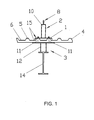
- FIG. 1 to 3 show a total of two safety devices according to the invention shown in sections and in cross section.
- These safety devices initially consist of a mounting flange 1.
- This is in the Cross section seen cup-shaped. Its rectangular in plan view Basic structure enables the support over two elevations 5 running in parallel of the roof equipped with elevations 5 and depressions 6 Elevations 5 and the depressions 6 are on the surface of the roof 4 arranged.
- the underside of the roof is flat here.
- the cross section seen cup-shaped design of the mounting flange 1 it has a shielding Function. Rainwater can therefore along the wells and to drain freely without the sealing function of the roof through the safety device according to the invention is impaired.
- a safety bracket is made in one piece was designated a total of 2.
- the safety bracket 2 has in its upper section facing away from the mounting flange 1 has a receiving opening 8 in Form of a safety eyelet. Through this receiving opening 8 can, for example a safety rope to guide the person to be secured haltem.
- a support element which has a total of 3 was designated below the roof 4 . In the simplest case, this support element can Carrier 14 be.
- FIGS. 1 to 3 an assembly was used as the supporting element 3 used, the present from a carrier 14, which here as a double-T carrier and an intermediate flange 12 fastened on this carrier 14 consists.
- the roof 4 is in a solution according to the invention between the Intermediate flange 12 and the mounting flange 1 arranged.
- the components of the safety device serve sealing screws 11, which from the top of the roof through the mounting flange 1 and the roof 4 through until the screw head on the mounting flange 1 rests.
- Stiffening elements 9 are present, which is the safety bracket designed as a flat profile 7 support.
- seals 15 are provided.
- This can consist of a glued on sealing tape, so that the assembly too here is not complicated by the application of the seal.
- the intermediate flanges 12 are only to be provided where a safety bracket is attached to the roof.
- 12 purlins 13 are provided spaced apart from the intermediate flanges. These bridge the distance between the underside of the roof 4 and the carrier 14 in a manner known per se.
- the carrier 14 is, for example, part of a supporting structure for a hall made of steel girders.
- a safety device according to the invention is particularly suitable for this application.
Landscapes
- Engineering & Computer Science (AREA)
- Architecture (AREA)
- Mechanical Engineering (AREA)
- Civil Engineering (AREA)
- Structural Engineering (AREA)
- Health & Medical Sciences (AREA)
- General Health & Medical Sciences (AREA)
- Business, Economics & Management (AREA)
- Emergency Management (AREA)
- Emergency Lowering Means (AREA)
- Roof Covering Using Slabs Or Stiff Sheets (AREA)
Abstract
Es wird eine Sicherheitsvorrichtung zur Absicherung auf Dächem tätiger Personen vorgestellt, die aus mindestens einer mit einem Montageflansch (1) verbundenen Sicherheitshalterung (2) besteht. Der Montageflansch (1) ist an oder in Tragelementen (3) eines Daches (4) befestigt. Die erfindungsgemäße Sicherheitsvorrichtung eignet sich insbesondere für ein Dach (4) mit einer profilierten oder wellenförmigen Oberfläche, also mit sich abwechselnden Erhebungen (5) und Vertiefungen (6). Das Dach (4) ist bei dieser Lösung zwischen dem Montageflansch (1) und den Tragelementen (3) angeordnet. Ferner wird ein Montageverfahren für die erfindungsgemäße Sicherheitsvorrichtung beschrieben. <IMAGE>A safety device for securing people working on roofs is presented, which consists of at least one safety bracket (2) connected to a mounting flange (1). The mounting flange (1) is attached to or in support elements (3) of a roof (4). The safety device according to the invention is particularly suitable for a roof (4) with a profiled or undulating surface, that is to say with alternating elevations (5) and depressions (6). In this solution, the roof (4) is arranged between the mounting flange (1) and the support elements (3). Furthermore, an assembly method for the safety device according to the invention is described. <IMAGE>
Description
Die Erfindung betrifft eine Sicherheitsvorrichtung zur Absicherung auf Dächern tätiger Personen und besteht aus mindestens einer mit einem Montageflansch verbundenen Sicherheitshalterung, wobei der Montageflansch an oder in Tragelementen eines Daches befestigt ist.The invention relates to a security device for securing on roofs active persons and consists of at least one with a mounting flange connected safety bracket, the mounting flange on or in Support elements of a roof is attached.
Als Tragelemente für Dächer sind beispielsweise Holzbalken, Stahlträger oder Betondecken geeignet. Die Montageflansche bekannter Sicherheitsvorrichtungen werden für Flachdächer eingesetzt, wobei bei Verwendung von Betondecken zumeist die Befestigung mittels einer Schraube-Dübel-Verbindung erfolgt.As supporting elements for roofs are, for example, wooden beams, steel beams or Suitable for concrete ceilings. The mounting flanges of known safety devices are used for flat roofs, whereby when using concrete ceilings mostly the attachment is made by means of a screw-dowel connection.
Wie aus dem Firmenprospekt "Securant" der Firma Schierling KG für derartige Sicherheitsvorrichtungen hervorgeht, durchdringt die Sicherheitshalterung das Dach vollständig. Um die Sicherheitsvorrichtung an den Tragelementen montieren zu können, muss in dem Flachdach eine Öffnung vorgesehen oder nachträglich aus dem Dach herausgearbeitet werden, die den Montageflanschabmessungen entspricht. Der Montageflansch, welcher einteilig mit der Sicherheitshalterung ausgeführt ist, kann durch diese Öffnung des Daches unmittelbar an den darunter befindlichen Tragelementen befestigt werden. Anschließend muss die Öffnung im Dach wieder verschlossen und dabei sorgfältig abgedichtet werden. Bei diesen Ausführungen ist es zudem erforderlich, eine Schutzkappe vorzusehen, welche über die Sicherheitshalterung gestülpt wird, wenn diese nicht in Gebrauch ist, um eine sichere Abdichtung des Flachdaches zu erreichen. As from the company brochure "Securant" from Schierling KG for such Safety devices emerges, the safety bracket penetrates the roof Completely. To mount the safety device on the support elements an opening in the flat roof must be provided or subsequently made the roof are worked out, the the mounting flange dimensions equivalent. The mounting flange, which is in one piece with the safety bracket can be directly through this opening of the roof to the one below existing support elements are attached. Then the opening in the Close the roof again and seal it carefully. With these Versions, it is also necessary to provide a protective cap, which is placed over the safety holder when it is not in use in order to to achieve a secure seal of the flat roof.
Bei den aus dem Stand der Technik bekannten Ausführungen ist nicht nur die Montage sehr aufwendig, es stellen sich darüber hinaus Probleme bei der sicheren Abdichtung einer derartigen Sicherheitsvorrichtung ein. Auch wenn man den genannten Nachteilen einigermaßen entsprechen kann, sind derartige Sicherheitsvorrichtungen beispielsweise für Dächer mit einer profilierten Oberfläche wie Wellblechdächer überhaupt nicht einsetzbar.In the designs known from the prior art, not only that Assembly very complex, there are also problems with the safe Sealing of such a safety device. Even if you mentioned disadvantages can correspond to some extent, are such Safety devices, for example for roofs with a profiled surface such as corrugated iron roofs cannot be used at all.
Der Erfindung liegt die technische Problemstellung zugrunde, eine Sicherheitsvorrichtung zu schaffen, die für Dächer mit profilierten oder wellenförmigen Oberflächen einsetzbar ist und darüber hinaus ein Verfahren zur Montage einer derartigen Sicherheitsvorrichtung auf den entsprechenden Dächern zur Verfügung zu stellen.The invention is based on the technical problem, a safety device to create that for profiled or wavy roofs Can be used and also a method for assembling a surface such security device on the appropriate roofs available to deliver.
Die Erfindung löst diese technische Problemstellung mit den kennzeichnenden
Merkmalen des Patentanspruches 1 sowie mit den Verfahrensmerkmalen des
Patentanspruches 11.The invention solves this technical problem with the characteristic
Features of
Ein Dach mit einer profilierten oder wellenförmigen Oberfläche weist sich abwechselnde zumeist parallele Erhebungen und Vertiefungen auf. Gemäß der vorliegenden Erfindung wird zur Lösung der eingangs genannten technischen Problemstellung vorgeschlagen, das Dach insgesamt zwischen dem Montageflansch mit der Sicherheitshalterung und den Tragelementen anzuordnen. Diese erfindungsgemäße Ausführungsform hat den entscheidenden Vorteil, dass keine Öffnung mehr erforderlich ist, durch die die Sicherheitshalterung das Dach durchdringt. Demgemäß vereinfacht sich auch die Montage in erheblichem Maße, ohne dass Einbußen an der zur Absicherung der auf dem Dach tätigen Personen erforderlichen Sicherheit hingenommen werden müssen. Die Anordnung des Daches zwischen dem Montageflansch der Sicherheitshalterung und den Tragelementen gestattet in einfacher Weise eine hervorragende Abdichtung des Gesamtsystems.A roof with a profiled or wavy surface shows alternating mostly parallel elevations and depressions. According to the The present invention is used to solve the aforementioned technical Problem proposed, the roof altogether between that To arrange the mounting flange with the safety bracket and the support elements. This embodiment according to the invention has the decisive advantage that No opening is required through which the security bracket opens the roof penetrates. Accordingly, assembly is also considerably simplified, without sacrificing security for those working on the roof necessary security must be accepted. The arrangement of the Roof between the mounting flange of the safety bracket and the support elements allows an excellent sealing of the entire system in a simple manner.
Weitere Ausgestaltungen der Erfindung sind Gegenstand der Unteransprüche. Further embodiments of the invention are the subject of the dependent claims.
Gemäß einer weiteren Ausgestaltung der Erfindung wird der Montageflansch als Passblech ausgeführt, welches im Querschnitt betrachtet einen annähernd tassenförmigen oder U-förmigen Querschnitt aufweisen kann.According to a further embodiment of the invention, the mounting flange is as Fitting plate executed, which in cross-section looks like an approximation can have cup-shaped or U-shaped cross section.
Durch die tassenförmige beziehungsweise U-förmige Querschnittsgeometrie des Montageflansches ist es dementsprechend möglich, dass dieser beispielsweise wenigstens zwei Erhebungen des Daches überspannt. Dadurch wird insgesamt eine sichere Befestigung der Sicherheitshalterung ermöglicht und eine einfache Abdichtung gewährleistet.Due to the cup-shaped or U-shaped cross-sectional geometry of the Mounting flange, it is accordingly possible that this, for example spanned at least two elevations of the roof. This will total enables a secure attachment of the safety bracket and a simple one Sealing guaranteed.
Die Randbereiche, welche in Richtung der Vertiefungen des Daches umgebogen sind, sollten mit einem möglichst geringen Abstand die Erhebungen des Daches überragen. Somit kann beispielsweise Regenwasser über die Vertiefungen des Daches abtransportiert werden, ohne dass dieses in die Verschraubungen der Sicherheitsvorrichtung eindringen kann.The edge areas, which are bent in the direction of the depressions of the roof the elevations of the roof should be as close as possible overtop. Thus, for example, rainwater over the wells of the Can be transported away without this in the screw connections of the Security device can penetrate.
Die Verschraubungen werden nämlich vorzugsweise an den bereits erwähnten Erhebungen des Daches vorgesehen.The screw connections are namely preferably at the elevations already mentioned of the roof.
Um die erfindungsgemäße Sicherheitsvorrichtung insgesamt einfach gestalten zu können, ist es ferner vorteilhaft, die Sicherheitshalterung unlösbar mit dem Montageflansch auszuführen.To make the safety device according to the invention simple overall can, it is also advantageous to make the safety bracket non-detachable from the mounting flange perform.
Die Sicherheitshalterung kann aus einem Flachprofil oder aus einem Zylinderprofil bestehen. Sofern ein Flachprofil als Sicherheitshalterung zum Einsatz kommt, sollten zur Verbesserung der Abstützungsfunktion Versteifungselemente vorgesehen werden.The safety bracket can be made from a flat profile or from a cylinder profile consist. If a flat profile is used as a safety bracket, stiffening elements should be provided to improve the support function become.
Die Sicherheitshalterung weist unabhängig von ihrem geometrischen Querschnitt jeweils eine Aufnahmeöffnung auf, durch welche beispielsweise Sicherheitsseile hindurch geführt werden können oder in welche Sicherheitshaken einsetzbar sind. Dementspechend kann die Aufnahmeöffnung eine an der Sicherheitshalterung angeformte oder daran befestigte Sicherheitsöse sein. The safety bracket shows regardless of its geometric cross-section each have a receiving opening through which, for example, safety ropes can be passed through or in which safety hooks can be used. Accordingly, the receiving opening on the safety bracket molded or attached safety eyelet.
Gemäß einer vorteilhaften Ausgestaltung der Erfindung sollte das Dach im Sinne der nachfolgend noch zu beschreibenden Verfahrensmerkmale aus mehreren sandwichförmigen Einzelelementen zusammengesetzt sein, die übereinander geschichtet oder ineinander einsetzbar sind. Dadurch lässt sich die Montage des Daches in erheblichem Maße vereinfachen.According to an advantageous embodiment of the invention, the roof should be in the sense the process features to be described below from several sandwich-like individual elements can be assembled, one above the other are layered or can be used in one another. This allows the assembly of the Simplify the roof considerably.
Eine sehr vorteilhafte und einfache Ausführungsform einer erfindungsgemäßen Sicherheitsvorrichtung wird weiterhin darin gesehen, dass die Tragelemente Träger sind, an denen der Montageflansch mit selbstschneidenden Dichtschrauben angeschraubt ist. Diese Dichtschrauben durchsetzen das Dach vollständig. Als Dichtschrauben sind jegliche Art von Schrauben anzusehen, die eine sichere Abdichtung gegen das Eindringen von Feuchtigkeit in das Dachinnere beziehungsweise die darunter befindlichen Räume gewährleisten. Nur beispielhaft seien hier Schrauben erwähnt, die mit einer Schutzkappe versehen sind oder die eine Dichtungsmasse in ihren oberen Gewindegängen aufweisen beziehungsweise bei denen eine Dichtscheibe zwischen dem Schraubenkopf und der Oberfläche, an welcher der Schraubenkopf anliegt, aufweisen.A very advantageous and simple embodiment of an inventive Safety device is also seen in the fact that the support elements are carriers on which the mounting flange with self-tapping sealing screws is screwed on. These sealing screws penetrate the roof completely. As Sealing screws are to be regarded as any type of screw that is secure Sealing against the ingress of moisture into the roof or respectively ensure the rooms below. Here are only examples Screws mentioned, which are provided with a protective cap or one Have sealant in their upper threads or at which a sealing washer between the screw head and the surface which the screw head rests on.
Als Träger können erfindungsgemäß sämtliche Arten von Trägem zum Einsatz kommen, also beispielsweise T-Träger, Doppel-T-Träger, Holzbalken oder andere Profilformen. Auch der Materialwahl der Träger sind nahezu keine Grenzen gesetzt. Eine Auslegung derselben erfolgt lediglich in Abhängigkeit der aufzunehmenden Traglast.According to the invention, all types of carriers can be used as carriers come, for example T-beams, double-T beams, wooden beams or others Profile forms. There are almost no limits to the choice of material for the beams. The same is interpreted only depending on the one to be included Load.
Gemäß einer spezielleren Ausgestaltung der vorliegenden Erfindung können die
Tragelemente Baugruppen bilden, die entweder aus einem Träger und mindestens
einer Pfette besteht oder aus einem Träger mit je Sicherheitsvorrichtung einem
daran befestigten Zwischenflansch. Auch hierbei wird der Montageflansch mit
selbstschneidenden Dichtschrauben an seinem ihm jeweils zugeordneten
Zwischenflansch angeschraubt. Die Dichtschrauben durchdringen das Dach
vollständig.
Mit einer erfindungsgemäßen Sicherheitsvorrichtung wurde insgesamt eine sehr
einfache Möglichkeit geschaffen, Dächer, die bislang als Problemfall für die
Anbringung von Sicherheitsvorrichtungen galten, mit einer solchen auszustatten.
Diese mit einer profilierten oder wellenförmigen Oberfläche versehenen Dächer
können nunmehr auch mit Sicherheitsvorrichtungen zur Absicherung der auf den
Dächern tätigen Personen versehen werden, wobei die Abdichtung nach außen
ebenfalls erheblich vereinfacht und verbessert wurde.According to a more specific embodiment of the present invention, the support elements can form assemblies which either consist of a carrier and at least one purlin or of a carrier with an intermediate flange attached to each safety device. Here, too, the mounting flange is screwed to its associated intermediate flange with self-tapping sealing screws. The sealing screws penetrate the roof completely.
With a security device according to the invention, a very simple possibility was created overall to equip roofs, which were previously considered to be a problem for the attachment of security devices. These roofs, which are provided with a profiled or undulating surface, can now also be provided with safety devices for securing the people working on the roofs, the sealing to the outside also being considerably simplified and improved.
Ein erfindungsgemäßes Montageverfahren einer Sicherheitsvorrichtung weist hauptsächlich nachfolgende Verfahrensschritte auf:
- Auflage des Daches auf die Tragelemente bei gleichzeitiger Kennzeichnung der Befestigungspunkte des Montageflansches der Sicherheitshalterung,
- Anbringung von Dichtungen an den Erhebungen des Daches und Aufsetzen des Montageflansches mit der Sicherheitshalterung auf die abgedichteten Stellen und
- Montage der Sicherheitsvorrichtung sowie abdichtende Befestigung des Daches an den Tragelementen.
- Support of the roof on the supporting elements with simultaneous identification of the fastening points of the mounting flange of the safety bracket,
- Attach seals to the elevations of the roof and place the mounting flange with the safety bracket on the sealed points and
- Installation of the safety device and sealing fastening of the roof to the support elements.
Zwei bevorzugte Ausführungsformen einer erfindungsgemäßen Sicherheitsvorrichtung
werden nachfolgend anhand der Figuren näher beschrieben.
Es zeigen:
Show it:
in den Figuren 1 bis 3 sind insgesamt zwei erfindungsgemäße Sicherheitsvorrichtungen
ausschnittsweise und im Querschnitt gezeigt. Diese Sicherheitsvorrichtungen
bestehen zunächst aus einem Montageflansch 1. Dieser ist im
Querschnitt gesehen tassenförmig ausgeführt. Seine in der Draufsicht rechteckige
Grundstruktur ermöglicht die Auflage über zwei parallel verlaufende Erhebungen 5
des mit Erhebungen 5 und Vertiefungen 6 ausgestatteten Daches 4. Die
Erhebungen 5 sowie die Vertiefungen 6 sind auf der Oberfläche des Daches 4
angeordnet. Die Dachunterseite ist vorliegend eben. Durch die im Querschnitt
gesehen tassenförmige Gestaltung des Montageflansches 1 hat er eine abschirmende
Funktion. Regenwasser kann demnach die Vertiefungen entlang und
damit ungehindert abfließen, ohne dass die Dichtfunktion des Daches durch die
erfindungsgemäße Sicherheitsvorrichtung beeinträchtigt wird.1 to 3 show a total of two safety devices according to the invention
shown in sections and in cross section. These safety devices
initially consist of a
Mit dem Montageflansch 1 ist eine Sicherheitshalterung einstückig ausgeführt, die
insgesamt mit 2 bezeichnet wurde. Die Sicherheitshalterung 2 weist in ihrem
oberen, dem Montageflansch 1 abgewandten Abschnitt eine Aufnahmeöffnung 8 in
Form einer Sicherheitsöse auf. Durch diese Aufnahmeöffnung 8 kann beispielsweise
ein Sicherungsseil geführt werden, um die abzusichernde Person daran zu
haltem. Unterhalb des Daches 4 ist ein Tragelement, welches insgesamt mit 3
bezeichnet wurde, angeordnet. Im einfachsten Fall kann dieses Tragelement ein
Träger 14 sein. In den Figuren 1 bis 3 wurde als Tragelement 3 eine Baugruppe
eingesetzt, die vorliegend aus einem Träger 14, welcher hier als Doppel-T-Träger
ausgeführt ist, und einem auf diesem Träger 14 befestigten Zwischenflansch 12
besteht. Das Dach 4 ist bei einer erfindungsgemäßen Lösung zwischen dem
Zwischenflansch 12 und dem Montageflansch 1 angeordnet. Zur gegenseitigen
Befestigung der Bauteile der Sicherheitsvorrichtung dienen Dichtschrauben 11,
welche von der Dachoberseite her durch den Montageflansch 1 und das Dach 4
hindurch geführt werden, bis der Schraubenkopf auf dem Montageflansch 1
aufliegt. Auf der Gegenseite greifen diese als selbstschneidende Dichtschrauben
ausgeführten Befestigungsmittel in den Zwischenflansch 12 ein, sodass die
Montage der Gesamtbaugruppe in einfacher Weise von der Dachoberfläche aus
erfolgen kann.With the mounting
Die Unterschiede zwischen den Figuren 1 und 2 bestehen lediglich darin, dass bei
der Figur 1 ein zylinderförmiges Profil als Sicherheitshalterung 2 zum Einsatz
kommt und bei der Ausführung entsprechend Figur 2 ein Flachprofil 7 als
Sicherheitshalterung 2 dient. The only difference between Figures 1 and 2 is that at
1 shows a cylindrical profile as a
Bei der in Figur 2 gezeigten Sicherheitsvorrichtung sind zudem
Versteifungselemente 9 vorhanden, die die als Flachprofil 7 ausgeführte Sicherheitshalterung
abstützen.In the safety device shown in Figure 2 are also
Stiffening elements 9 are present, which is the safety bracket designed as a
Um eine optimale Abdichtung des Daches zu gewährleisten, sind wenigstens unter
den Schraubenköpfen der Dichtschrauben 11 Dichtungen 15 vorgesehen. Zur
Verbesserung der Dichtwirkung ist es jedoch sinnvoll, auch zwischen der
Dachoberfläche und dem Montageflansch 1 eine weitere Dichtung 15 anzuordnen.
Diese kann aus einem aufgeklebten Dichtband bestehen, sodass die Montage auch
hier durch das Aufbringen der Dichtung nicht erschwert wird.To ensure an optimal sealing of the roof, at least below
the screw heads of the sealing screws 11
Wie anschaulich aus der Figur 3 hervorgeht, sind die Zwischenflansche 12 lediglich
dort vorzusehen, wo eine Sicherheitshalterung an dem Dach angebracht ist. Um die
Tragfunktion des Daches zu gewährleisten, sind beabstandet zu den
Zwischenflanschen 12 Pfetten 13 vorhanden. Diese überbrücken den Abstand
zwischen der Unterseite des Daches 4 und dem Träger 14 in an sich bekannter
Weise.
Der Träger 14 ist beispielsweise Bestandteil einer Tragkonstruktion für eine aus
Stahlträgem hergestellte Halle. Für diesen Anwendungsfall ist eine erfindungsgemäße
Sicherheitsvorrichtung in besonderer Weise geeignet. As can be clearly seen from FIG. 3, the
The
- 11
- Montageflanschmounting flange
- 22
- Sicherheitshalterungsafety bracket
- 33
- Tragelementsupporting member
- 44
- Dachtop, roof
- 55
- Erhebungsurvey
- 66
- Vertiefungdeepening
- 77
- Flachprofillow profile
- 88th
- Aufnahmeöffnungreceiving opening
- 99
- Versteifungselementstiffener
- 1010
- Zylinderprofilcylinder profile
- 1111
- Dichtschraubesealing screw
- 1212
- ZwischenflanschWafer
- 1313
- Pfettepurlin
- 1414
- Trägercarrier
- 1515
- Dichtungpoetry
Claims (11)
dadurch gekennzeichnet, dass
das eine profilierte oder wellenförmige Oberfläche mit sich abwechselnden Erhebungen (5) und Vertiefungen (6) aufweisende Dach (4) zwischen dem Montageflansch (1) und den Tragelementen (3) angeordnet ist.Safety device for securing people working on roofs, comprising at least one safety bracket (2) connected to a mounting flange (1), the mounting flange (1) being fastened to or in supporting elements (3) of a roof (4),
characterized in that
the roof (4) having a profiled or undulating surface with alternating elevations (5) and depressions (6) is arranged between the mounting flange (1) and the support elements (3).
dadurch gekennzeichnet, dass
der Montageflansch (1) ein Passblech mit einem tassenförmigen oder annähernd U-förmigen Querschnitt ist. Safety device according to claim 1,
characterized in that
the mounting flange (1) is a fitting plate with a cup-shaped or approximately U-shaped cross section.
dadurch gekennzeichnet, dass
der Montageflansch (1) mindestens zwei Erhebungen (5) des Daches (4) überspannt.Safety device according to claim 2,
characterized in that
the mounting flange (1) spans at least two elevations (5) of the roof (4).
dadurch gekennzeichnet, dass
die Sicherheitshalterung (2) unlösbar mit dem Montageflansch (1) verbunden ist und aus einem Flachprofil (7) mit einer Aufnahmeöffnung (8) besteht.Safety device according to one of the preceding claims,
characterized in that
the safety bracket (2) is inseparably connected to the mounting flange (1) and consists of a flat profile (7) with a receiving opening (8).
dadurch gekennzeichnet, dass
der Montageflansch (1) Versteifungselmente (9) zur Stabilisierung des Flachprofiles (7) aufweist.Safety device according to claim 4,
characterized in that
the mounting flange (1) has stiffening elements (9) for stabilizing the flat profile (7).
dadurch gekennzeichnet, dass
die Sicherheitshalterung (2) unlösbar mit dem Montageflansch (1) verbunden ist und aus einem Zylinderprofil (10) mit einer Aufnahmeöffnung (8) besteht.Safety device according to one of claims 1 to 3
characterized in that
the safety bracket (2) is non-detachably connected to the mounting flange (1) and consists of a cylinder profile (10) with a receiving opening (8).
dadurch gekennzeichnet, dass
die Aufnahmeöffnung (8) eine an der Sicherheitshalterung (2) angeformte, daran befestigte oder darin vorhandene Sicherheitsöse ist.Safety device according to claim 4 or 6
characterized in that
the receiving opening (8) is a safety eyelet which is formed on the safety bracket (2), fastened thereon or is present therein.
dadurch gekennzeichnet, dass
das Dach (4) aus mehreren sandwichförmigen Einzelelmenten zusammengesetzt ist.Security device according to one of the preceding claims
characterized in that
the roof (4) is composed of several sandwich-like individual elements.
dadurch gekennzeichnet, dass
die Tragelemente (3) Träger (14) sind, an denen der Montageflansch (1) mit selbstschneidenden Dichtschrauben (11) angeschraubt ist, die das Dach (4) vollständig durchsetzen.Security device according to one of the preceding claims
characterized in that
the support elements (3) are supports (14), to which the mounting flange (1) is screwed with self-tapping sealing screws (11) which completely penetrate the roof (4).
dadurch gekennzeichnet, dass
die Tragelemente (3) jeweils eine Baugruppe bestehend aus einem Träger (14) und mindestens einer Pfette (13) beziehungsweise aus einem Träger (14) mit je Sicherheitsvorrichtung einem daran befestigten Zwischenflansch (12) bilden, wobei an jedem Zwischenflansch (12) je ein Montageflansch (1) mit selbstschneidenden Dichtschrauben (11) angeschraubt ist und die Dichtschrauben (11) das Dach (4) vollständig durchsetzen.Safety device according to one of claims 1 to 8,
characterized in that
the supporting elements (3) each form an assembly consisting of a support (14) and at least one purlin (13) or of a support (14) with an intermediate flange (12) attached to each safety device, one on each intermediate flange (12) Mounting flange (1) is screwed on with self-tapping sealing screws (11) and the sealing screws (11) completely penetrate the roof (4).
Applications Claiming Priority (2)
| Application Number | Priority Date | Filing Date | Title |
|---|---|---|---|
| DE10052572 | 2000-10-23 | ||
| DE10052572A DE10052572C2 (en) | 2000-10-23 | 2000-10-23 | safety device |
Publications (1)
| Publication Number | Publication Date |
|---|---|
| EP1219762A2 true EP1219762A2 (en) | 2002-07-03 |
Family
ID=7660802
Family Applications (1)
| Application Number | Title | Priority Date | Filing Date |
|---|---|---|---|
| EP01120527A Pending EP1219762A2 (en) | 2000-10-23 | 2001-08-29 | Security device for the protection of a person working on a roof |
Country Status (2)
| Country | Link |
|---|---|
| EP (1) | EP1219762A2 (en) |
| DE (1) | DE10052572C2 (en) |
Cited By (1)
| Publication number | Priority date | Publication date | Assignee | Title |
|---|---|---|---|---|
| EP2767652A2 (en) | 2013-02-14 | 2014-08-20 | Torbau Schmidiger | Fall protection device on roofs |
Families Citing this family (1)
| Publication number | Priority date | Publication date | Assignee | Title |
|---|---|---|---|---|
| NL1032405C2 (en) * | 2006-09-01 | 2008-03-04 | Cladding Partners B V | Building roof involves protective anchors to ensure safety of roof workers |
Family Cites Families (1)
| Publication number | Priority date | Publication date | Assignee | Title |
|---|---|---|---|---|
| DD281847A5 (en) * | 1988-12-22 | 1990-08-22 | Kooperative Einrichtung Landba | ARRANGEMENT FOR FIXING FALL PROTECTION AGENTS |
-
2000
- 2000-10-23 DE DE10052572A patent/DE10052572C2/en not_active Expired - Fee Related
-
2001
- 2001-08-29 EP EP01120527A patent/EP1219762A2/en active Pending
Cited By (1)
| Publication number | Priority date | Publication date | Assignee | Title |
|---|---|---|---|---|
| EP2767652A2 (en) | 2013-02-14 | 2014-08-20 | Torbau Schmidiger | Fall protection device on roofs |
Also Published As
| Publication number | Publication date |
|---|---|
| DE10052572A1 (en) | 2002-05-02 |
| DE10052572C2 (en) | 2002-11-28 |
Similar Documents
| Publication | Publication Date | Title |
|---|---|---|
| DE102005027592A1 (en) | Device for securing people on roofs, in particular flat roofs, persons | |
| EP1947260B1 (en) | Facility for supplying a particularly sloped roof substructure | |
| DE10052572C2 (en) | safety device | |
| DE102015100700A1 (en) | Roof fuse holder | |
| DE102010037831A1 (en) | Fastening device on a building | |
| EP0433236B1 (en) | Supporting construction for roof covering | |
| DE102012105985A1 (en) | Device for protecting people against crash by roof, has metal rope connection comprising stainless steel rope and arranged in inner side of post, where connection is provided for tight connection of eyelet in anchorage area of device | |
| DE3440012A1 (en) | Device for holding masts for outdoor antennas | |
| DE102010001692A1 (en) | Hood for placing on a concrete post | |
| DE202008008405U1 (en) | connecting fitting | |
| EP0243526A1 (en) | Drive-in screw | |
| WO1982004283A1 (en) | Anchoring of dog-spikes in concrete elements or the like | |
| AT402833B (en) | DEVICE FOR FASTENING FIRST COVERS ON THE ROOF ROOF OF A ROOF COVER | |
| DE102018114871A1 (en) | Installation arrangement for a floor ceiling | |
| DE3420841A1 (en) | CONNECTING DEVICE FOR CREATING A MULTI-DIMENSIONAL CONSTRUCTION | |
| EP0524631A1 (en) | Mounting device for insulating glazing | |
| DE202017103966U1 (en) | Retaining clip for a roof tile | |
| DE4313728C1 (en) | Protection device to avoid corrosion of building materials | |
| DE102016216212A1 (en) | Roofing device and method for producing a roofing device | |
| DE10324293B3 (en) | Safety harness roof anchorage fitting is attached to an upright post inside the building with safety wire extending through window | |
| DE102014003761B4 (en) | Fixing device for sheets of metal facades and roofs | |
| DE102015205715A1 (en) | Mounting arrangement for personal and / or property protection on roofs | |
| DE102005001216B4 (en) | retaining profile | |
| DE102018123598A1 (en) | Profile construction and assembly process | |
| DE19914847A1 (en) | Anchor for a reinforcement plate at a concrete construction component is over the plate on the flat surface bonded into openings in the concrete |
Legal Events
| Date | Code | Title | Description |
|---|---|---|---|
| PUAI | Public reference made under article 153(3) epc to a published international application that has entered the european phase |
Free format text: ORIGINAL CODE: 0009012 |
|
| AK | Designated contracting states |
Kind code of ref document: A2 Designated state(s): AT BE CH CY DE DK ES FI FR GB GR IE IT LI LU MC NL PT SE TR |
|
| AX | Request for extension of the european patent |
Free format text: AL;LT;LV;MK;RO;SI |
|
| 18W | Application withdrawn |
Effective date: 20040117 |
|
| D18W | Application withdrawn (deleted) | ||
| STAA | Information on the status of an ep patent application or granted ep patent |
Free format text: STATUS: THE APPLICATION IS DEEMED TO BE WITHDRAWN |
|
| 18D | Application deemed to be withdrawn |
Effective date: 20040302 |