EP1219414A2 - Verfahren und Vorrichtung zur Einstellung des Ruheabstandes eines Gravurstichels von der Zylinderoberfläche eines Tiefdruckformzylinders - Google Patents
Verfahren und Vorrichtung zur Einstellung des Ruheabstandes eines Gravurstichels von der Zylinderoberfläche eines Tiefdruckformzylinders Download PDFInfo
- Publication number
- EP1219414A2 EP1219414A2 EP01127506A EP01127506A EP1219414A2 EP 1219414 A2 EP1219414 A2 EP 1219414A2 EP 01127506 A EP01127506 A EP 01127506A EP 01127506 A EP01127506 A EP 01127506A EP 1219414 A2 EP1219414 A2 EP 1219414A2
- Authority
- EP
- European Patent Office
- Prior art keywords
- engraving
- cylinder
- stylus
- engraving stylus
- measuring
- Prior art date
- Legal status (The legal status is an assumption and is not a legal conclusion. Google has not performed a legal analysis and makes no representation as to the accuracy of the status listed.)
- Granted
Links
Images



Classifications
-
- B—PERFORMING OPERATIONS; TRANSPORTING
- B41—PRINTING; LINING MACHINES; TYPEWRITERS; STAMPS
- B41C—PROCESSES FOR THE MANUFACTURE OR REPRODUCTION OF PRINTING SURFACES
- B41C1/00—Forme preparation
- B41C1/02—Engraving; Heads therefor
- B41C1/04—Engraving; Heads therefor using heads controlled by an electric information signal
-
- B—PERFORMING OPERATIONS; TRANSPORTING
- B41—PRINTING; LINING MACHINES; TYPEWRITERS; STAMPS
- B41M—PRINTING, DUPLICATING, MARKING, OR COPYING PROCESSES; COLOUR PRINTING
- B41M2205/00—Printing methods or features related to printing methods; Location or type of the layers
- B41M2205/16—Correction processes or materials
Definitions
- the invention relates to a method for adjusting the resting distance of an engraving stylus for engraving a gravure cylinder from the cylinder surface of the gravure forme cylinder, including a cross to the axis of the Rotogravure cylinder adjustable sliding foot, which to guide the with the Engraving stylus connected to the sliding foot along the cylinder surface during the Engraving is provided.
- the invention relates to an adjusting device, preferably for implementation the aforementioned procedure.
- a printing form is usually inserted into the cylinder surface Gravure cylinder with one engraving stylus or with several engraving styluses engraved.
- the engraving stylus tip is usually made of diamond.
- the engraving stylus is used with a predetermined frequency and Amplitude driven vibrating. This basic vibration becomes the one to be seriously Image information superimposed as a signal, so that the engraving stylus corresponds to the Image information when it vibrates at different depths in the cylinder surface occurs or does not occur.
- the gravure form cylinder driven in rotation, and the engraving stylus is continuous or in steps moved in the axial direction along the cylinder surface to continue the Engraving image, which usually consists of a matrix of cells to achieve. It supports itself with its relative movement over the cylinder surface engraving head with a sliding foot, also preferred made of diamond, on the cylinder surface.
- This sliding foot can be used to vary the distance of the engraving head from the cylinder surface mostly by means of a Spindle extended or retracted transversely to the axis of the gravure cylinder , where "transverse” does not necessarily mean perpendicular to the axis and the The sliding foot does not necessarily have to lie in a radial jet to the axis, but rather For example, can also be aligned secant.
- the engraving stylus When the vibration drive is switched off, the engraving stylus is in its rest position at a small clear distance from the cylinder surface, this resting distance is determined by the adjustment of the extension length of the sliding foot. This resting distance must of course be very precise so that the image information engraved into the cylinder surface as intended.
- the position of the engraving tip corresponds to the zero crossing of the amplitude of the basic vibration of the engraving stylus without image information or with the image information on the corresponding Not to engrave the cylinder surface.
- the resting distance is z. B. 3 to 5 microns, preferably 4 microns, and should be at least 10% can be set precisely.
- the engraving stylus wears out over time or it can even to be damaged.
- the engraving stylus must therefore be relatively often against new ones Engraving stylus can be exchanged. After such an exchange the Resting distance can be set again because the engraving tips or cutting geometry of the engraving stylus match, but the engraving stylus otherwise do not have exactly the same overall lengths.
- the change the engraving stylus must, like the setting of the resting distance, in the Engraving operations are carried out more often, mostly more or less simultaneously for several engraving machines, since the gravure form cylinders are usually used for the different colors of a color print at about the same time be engraved.
- the procedure for adjusting the resting distance is that the new Engraving stylus is roughly positioned and then with a rotogravure cylinder the spindle of the sliding foot is slowly retracted until the engraving tip just lies on the cylinder surface and on it a very light one Leaves scratches that make this system recognizable. After that, with help its precision thread the spindle by exactly the desired rest distance extended again, which indirectly means this resting distance of the engraving stylus is produced.
- the invention is therefore based on the object, the adjustment of the resting distance a engraving stylus for gravure engraving economically, preferably also more precise and reproducible.
- this task is performed in a method of the type mentioned at the beginning Genus according to the invention solved in that the adjustment of the resting distance with respect to a cylinder surface replacing or representing Reference area is made.
- This measure according to the invention can advantageously be used in the engraving machine a gravure cylinder to be engraved remains and the engraving machine can also be used during the adjustment process, especially when if after a further development of the method it is provided that the engraving head or the slide foot with the engraving stylus connected to it on which the Adjustment is to be made during the adjustment from its working position spent, preferably taken from the engraving machine and preferred is replaced by an already set engraving head.
- the method according to the invention appears in that only one according to the invention Setting device for an entire set or stock of engraving machines must be provided.
- the engraving stylus is in principle in a tangential plane of the cylinder surface works, as after a development of the invention Procedures provided for easier adjustment and handling and setup a device according to the invention as a reference surface, a plane, preferably a flat surface of a plate can be used.
- control and measurement possibly also the setting process itself, as objectively as possible and reproducible, possibly even automated.
- the engraving stylus can be moved in by retracting the spindle Sliding foot are moved against a resilient area of the reference surface, whose yield is registered and measured with a sensor. This can then taken with the desired accuracy as a reference for adjustment be, the necessary movements preferably motor and not by a person can be made manually to achieve reproducible precision reach and jerky movements that can destroy the engraving stylus avoid. It can also be ensured that the setting is always with a certain direction of movement of the engraving stylus, system hysteresis or spindle inaccuracies in the measurement avoid. Of course, this also applies to methods of control other than mechanical.
- Another way of checking and measuring is with an optical one Method.
- the set idle distance between the engraving tip can be set directly and the reference surface and its change made visible and observed become.
- a measuring or scale microscope can be used for this become. This can be viewed directly, or it can the generated image via video camera on a screen in even more convenient Way be made visible, being through a in the transmission system generated projection factor an additionally better and more accurate scale selectable is.
- An additional more precise, more objective setting is also possible if the reference surface is mirrored or reflective, since then the (doubled) rest distance the engraving tip can be adjusted in relation to its reflection, a zero point to be precisely determined by the symmetry thereby obtained can be omitted, which may not be optically accurate enough to recognize and would be absolutely determined.
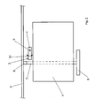
- Fig. 1 shows schematically in a side view the conventional working position of an engraving head 1 in an engraving machine (not shown) in one Side view.
- the engraving head 1 is on the cylinder surface of a gravure cylinder 2 employed.
- An engraving stylus 3 has a stylus holder 4 on the engraving head 1 is pivotable and about its, in the embodiment shown by 15 ° inclined stylus axis 5 arranged to be driven in a vibrating manner.
- the engraving head 1 is supported on the cylinder surface via a sliding foot 6.
- the sliding foot 6 can be extended and retracted with a spindle 7 and an adjusting wheel 8, whereby the rest distance of the tip of the engraving stylus 3 from the cylinder surface is set.
- the engraving head 1 is resiliently mounted on a support 9, not shown in detail, and that is pivotally mounted on leaf springs 10, which serve as a hinge and supported on coil springs 11.
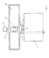
- FIG. 2 shows the area from FIG. 1 again in a top view. Same components are, as in the following figures, with the same reference numbers designated as in FIG. 1.
- FIG. 2 shows in particular the arrangement which can be pivoted in the direction of the double arrow 12 of the stylus holder 4 on the stylus axis 5 in the plan view.
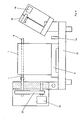
- FIG 3 shows a first exemplary embodiment of an adjusting device according to the invention, which works electromechanically, in the top view.
- the measuring pin 13 is supported by a spring 15 soft to a Avoid damaging the engraving stylus 3. That is why it becomes an engine used instead of the handwheel 8 to control the movement of the engraving stylus to be able to perform.
- the measuring pin 13 closes with its end face precisely deflected Surface of a ground stop plate 16 for the sliding foot 6.
- Fig. 4 shows the embodiment of Fig. 3 in a side view.
- the stop plate 16 with sensor 14 is for a problem-free changing of the stylus folded.
- the newly inserted engraving stylus can also be used in this position With the help of a camera, not shown, its height can be set. This will the engraving head 1 in a corresponding measuring device outside an engraving machine parked on a support 17 on which the stop plate 16 and Sensor 14 are pivoted up to a stop 19.
- the motor 18 can also be seen in FIG. 4, which has a V-belt 20 Spindle 7 drives.
- FIG. 5 shows the device according to FIG. 4 again in a side view as well folded drive unit (motor 18 and V-belt 20) for the sliding foot 6 or its spindle 7 in order to change or remove and insert the whole engraving head 1 in and out of the measuring device.
- the spindle has a pin 21 on.
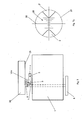
- FIG. 6 shows a second exemplary embodiment of an adjusting device according to the invention, which works optically, in a side view.
- the microscope 22 has an eyepiece micrometer for measurement on. The distance becomes the surface (reference surface 25) of a special one Measure reference plate 24.
- FIG. 7 shows the device according to FIG. 6 in a top view.
- the observation area the camera 23 or the microscope, not itself shown in FIGS. 7 and 7a 22 is marked there as a detail with a dashed line and labeled Vlla. This detail is highlighted in Fig. 7a.
- the reference surface 25 of the reference plate 24 is specular. Therefore with the Camera not only to recognize the stylus tip of the engraving stylus 3, but also also their reflection 3 'in the reference surface. This can the stylus tip is set symmetrically with respect to its own mirror image be what with a scale (eyepiece micrometer 26) in the eyepiece field of view 27 of the microscope 22 is measurable or verifiable.
Landscapes
- Engineering & Computer Science (AREA)
- Manufacturing & Machinery (AREA)
- Manufacture Or Reproduction Of Printing Formes (AREA)
Abstract
Description
- Fig. 1
- einen an einen Tiefdruckformzylinder angestellten Gravierkopf in einer Seitenansicht in einer nicht näher dargestellten Graviermaschine,
- Fig. 2
- den in Fig. 1 dargestellten Bereich in der Draufsicht,
- Fig. 3
- ein erstes, elektromechanisches Ausführungsbeispiel einer erfindungsgemäßen Einstellvorrichtung in der Draufsicht,
- Fig. 4
- das Ausführungsbeispiel gem. Fig. 3 in einer Seitenansicht für einen Stichelwechsel,
- Fig. 5
- das Ausführungsbeispiel gem. Fig. 4 für einen Gravierkopfwechsel,
- Fig. 6
- ein zweites, optisches Ausführungsbeispiel einer erfindungsgemäßen Einstellvorrichtung in einer Seitenansicht,
- Fig. 7
- das Ausführungsbeispiel gem. Fig. 6 in der Draufsicht und
- Fig. 7a
- das Detail Vlla aus Fig. 7 in einer Detailansicht.
Claims (15)
- Verfahren zur Einstellung des Ruheabstandes eines Gravurstichels für das Gravieren eines Tiefdruckformzylinders von der Zylinderoberfläche des Tiefdruckformzylinders unter Einbeziehung eines in Richtung quer zur Achse des Tiefdruckformzylinders verstellbaren Gleitfußes zur Führung des mit dem Gleitfuß verbundenen Gravurstichels entlang der Zylinderoberfläche,
dadurch gekennzeichnet, daß die Einstellung des Ruheabstandes bezüglich einer die Zylinderoberfläche ersetzenden bzw. repräsentierenden Referenzfläche vorgenommen wird. - Verfahren nach Anspruch 1, dadurch gekennzeichnet, daß der Gleitfuß mit dem mit ihm verbundenen Gravurstichel aus seiner Arbeitstellung in einer Graviermaschine vor der Einstellung verbracht wird und nach der Einstellung in die Arbeitsstellung zurück verbracht wird.
- Verfahren nach Anspruch 1 oder 2, dadurch gekennzeichnet, daß als Referenzfläche eine ebene Fläche, vorzugsweise einer Platte, verwendet wird.
- Verfahren nach einem der vorhergehenden Ansprüche, dadurch gekennzeichnet, daß die Einstellung mechanisch oder elektromechanisch kontrolliert und gemessen wird.
- Verfahren nach Anspruch 4, dadurch gekennzeichnet, daß bei der Einstellung der Gravurstichel definiert gegen einen beweglichen Anschlag gefahren bzw. bewegt wird, dessen Bewegung, vorzugsweise mittels einem Sensor, quantitativ kontrolliert und gemessen wird.
- Verfahren nach Anspruch 5, dadurch gekennzeichnet, daß der Gravurstichel maschinell und gesteuert bewegt wird.
- Verfahren nach einem der vorhergehenden Ansprüche, dadurch gekennzeichnet, daß die Einstellung optisch kontrolliert und gemessen wird.
- Verfahren nach Anspruch 7, dadurch gekennzeichnet, daß ein Meß- bzw. Skalenmikroskop verwendet wird.
- Vorrichtung zur Einstellung des Ruheabstandes eines Gravurstichels für das Gravieren eines Tiefdruckformzylinders von der Zylinderoberfläche des Tiefdruckformzylinders unter Einbeziehung eines in Richtung quer zur Achse des Tiefdruckformzylinders verstellbaren Gleitfußes zur Führung des mit dem Gleitfuß verbundenen Gravurstichels entlang der Zylinderoberfläche, vorzugsweise zur Durchführung des Verfahrens nach einem der vorhergehenden Ansprüche,
dadurch gekennzeichnet, daß sie eine die Zylinderfläche ersetzende Referenzfläche umfaßt. - Vorrichtung nach Anspruch 9, dadurch gekennzeichnet, daß die Referenzfläche eben ausgebildet ist.
- Vorrichtung nach Anspruch 9 oder 10, dadurch gekennzeichnet, daß sie eine Meß- und Kontrolleinrichtung umfaßt.
- Vorrichtung nach Anspruch 11, dadurch gekennzeichnet, daß die Meß- und Kontrolleinrichtung im wesentlichen elektromechanisch arbeitet.
- Vorrichtung nach Anspruch 12, dadurch gekennzeichnet, daß die Meß- und Kontrolleinrichtung einen Bewegungssensor umfaßt.
- Vorrichtung nach Anspruch 11, dadurch gekennzeichnet, daß die Meß- und Kontrolleinrichtung im wesentlichen optisch arbeitet.
- Vorrichtung nach Anspruch 14, dadurch gekennzeichnet, daß die Referenzfläche verspiegelt oder spiegelnd ist und daß von der Meß- und Kontrolleinrichtung die Spitze des Gravurstichels und gleichzeitig ihr Spiegelbild erfaßt wird.
Applications Claiming Priority (2)
| Application Number | Priority Date | Filing Date | Title |
|---|---|---|---|
| DE10064813 | 2000-12-22 | ||
| DE10064813 | 2000-12-22 |
Publications (3)
| Publication Number | Publication Date |
|---|---|
| EP1219414A2 true EP1219414A2 (de) | 2002-07-03 |
| EP1219414A3 EP1219414A3 (de) | 2004-01-02 |
| EP1219414B1 EP1219414B1 (de) | 2005-04-13 |
Family
ID=7668833
Family Applications (1)
| Application Number | Title | Priority Date | Filing Date |
|---|---|---|---|
| EP01127506A Expired - Lifetime EP1219414B1 (de) | 2000-12-22 | 2001-11-17 | Verfahren und Vorrichtung zur Einstellung des Ruheabstandes eines Gravurstichels von der Zylinderoberfläche eines Tiefdruckformzylinders |
Country Status (4)
| Country | Link |
|---|---|
| US (1) | US7031027B2 (de) |
| EP (1) | EP1219414B1 (de) |
| JP (1) | JP2002225215A (de) |
| DE (2) | DE50105897D1 (de) |
Family Cites Families (10)
| Publication number | Priority date | Publication date | Assignee | Title |
|---|---|---|---|---|
| US4837941A (en) * | 1987-10-28 | 1989-06-13 | Dana Corporation | Preset tool gauge |
| US4868994A (en) * | 1988-07-25 | 1989-09-26 | Pirce Kent H | Method and equipment for determining tool offsets from a reference position |
| US5737090A (en) * | 1993-02-25 | 1998-04-07 | Ohio Electronic Engravers, Inc. | System and method for focusing, imaging and measuring areas on a workpiece engraved by an engraver |
| US5867280A (en) * | 1993-02-25 | 1999-02-02 | Ohio Electronic Engravers, Inc. | Engraver with automatic tool changer |
| US5454306A (en) * | 1993-07-12 | 1995-10-03 | Ohio Electric Engravers, Inc. | Engraving head platform |
| US5475914A (en) * | 1993-08-10 | 1995-12-19 | Ohio Electronic Engravers, Inc. | Engraving head with cartridge mounted components |
| JP2895719B2 (ja) * | 1993-09-22 | 1999-05-24 | 大日本スクリーン製造株式会社 | グラビア彫刻機の彫刻ヘッド制御装置 |
| US5652659A (en) * | 1995-10-09 | 1997-07-29 | Ohio Electronic Engravers, Inc. | System and method for measuring run-out and other characteristics of a workpiece mounted on an engraver |
| DE19708469C2 (de) * | 1997-02-20 | 1998-12-24 | Gruner & Jahr | Verfahren zur Kalibrierung eines Graviersystems und Gravierverfahren |
| JP2000062395A (ja) * | 1998-08-24 | 2000-02-29 | Ando Electric Co Ltd | 彫刻ペン |
-
2001
- 2001-11-17 EP EP01127506A patent/EP1219414B1/de not_active Expired - Lifetime
- 2001-11-17 DE DE50105897T patent/DE50105897D1/de not_active Expired - Lifetime
- 2001-11-27 DE DE10158084A patent/DE10158084A1/de not_active Ceased
- 2001-12-19 US US10/025,015 patent/US7031027B2/en not_active Expired - Lifetime
- 2001-12-21 JP JP2001389725A patent/JP2002225215A/ja active Pending
Also Published As
| Publication number | Publication date |
|---|---|
| US20020089697A1 (en) | 2002-07-11 |
| EP1219414B1 (de) | 2005-04-13 |
| EP1219414A3 (de) | 2004-01-02 |
| US7031027B2 (en) | 2006-04-18 |
| DE50105897D1 (de) | 2005-05-19 |
| DE10158084A1 (de) | 2002-07-18 |
| JP2002225215A (ja) | 2002-08-14 |
Similar Documents
| Publication | Publication Date | Title |
|---|---|---|
| EP1407224B1 (de) | Verfahren zur messung von oberflächeneigenschaften sowie koordinatenmessgerät | |
| DE19616663B4 (de) | Meßgerät | |
| DE3841439C2 (de) | ||
| DE69000140T2 (de) | Schleifbearbeitungsverfahren mit messung einer formschleifscheibe und maschine zu dessen durchfuehrung. | |
| DE10322762B4 (de) | Halter für einen Rohling und Verfahren zur Vermessung der Lage und Orientierung des Halters | |
| DE19604354A1 (de) | Verfahren zur koordinatenmäßigen Vermessung von Werkstücken auf Bearbeitungsmaschinen | |
| EP0287758A2 (de) | Positionsmesseinrichtung | |
| EP0961118A2 (de) | Pipettierautomat | |
| DE19811459C1 (de) | Messvorrichtung für Sägeblätter | |
| DE1918898U (de) | Zusatzgeraet fuer eine vorrichtung zum messen der oberflachenrauhigkeit. | |
| EP1887311A2 (de) | Verfahren zum Messen der Mikrostruktur von Oberflächen von Zylinderbohrungen und Messvorrichtung zur Durchführung des Messverfahrens | |
| DE3808548A1 (de) | Messvorrichtung zur lagebestimmung von werkstueck-flaechen | |
| DE3320983A1 (de) | Transportables geraet zur pruefung des zahnflankenprofils und der zahnflankenlinien (zahnschraege) von zahnraedern auf verzahnmaschinen oder zahnflankenschleifmaschinen sowie zur positionierung dieses geraetes und zum orientieren des messtasters an der verzahnung fuer den messvorgang | |
| DE10123496A1 (de) | Verzahnungsmessmaschine | |
| EP1219414B1 (de) | Verfahren und Vorrichtung zur Einstellung des Ruheabstandes eines Gravurstichels von der Zylinderoberfläche eines Tiefdruckformzylinders | |
| DE60032635T2 (de) | Verfahren und vorrichtung zum testen von werkzeugmaschinen | |
| DE69520141T2 (de) | Verfahren und vorrichtung zur reparatur des chassis und/oder der karosserie eines kraftfahrzeuges | |
| DE102010011634B3 (de) | Verfahren zum Vermessen der Schneidengeometrie von Fräswerkzeugen | |
| DE102005006242A1 (de) | Schleifmaschine und Verfahren zum Einrichten eines Werkstückträgers an einer Schleifmaschine | |
| DE10319711A1 (de) | Verfahren zur hochgenauen dimensionalen Messung an Messobjekten | |
| DE19803360C2 (de) | Verfahren zur Montage einer Positionsmeßeinrichtung und Vorrichtung zur Durchführung des Verfahrens | |
| DE2615578C2 (de) | Einrichtung zum Einstellen der verstellbaren Spannleiste eines Rotationsdruck-Plattenzylinders | |
| DE932037C (de) | Vorrichtung zum Einstellen und Messen grosser Laengen | |
| WO2008012068A2 (de) | Sensor und vorrichtung zur prüfung von blattgut und verfahren zur sensor-vorjustage | |
| EP3536450B1 (de) | Vorrichtung zur einstellung und/oder vermessung eines werkzeugs |
Legal Events
| Date | Code | Title | Description |
|---|---|---|---|
| PUAI | Public reference made under article 153(3) epc to a published international application that has entered the european phase |
Free format text: ORIGINAL CODE: 0009012 |
|
| AK | Designated contracting states |
Kind code of ref document: A2 Designated state(s): AT BE CH CY DE DK ES FI FR GB GR IE IT LI LU MC NL PT SE TR |
|
| AX | Request for extension of the european patent |
Free format text: AL;LT;LV;MK;RO;SI |
|
| RAP1 | Party data changed (applicant data changed or rights of an application transferred) |
Owner name: HELL GRAVURE SYSTEMS GMBH |
|
| PUAL | Search report despatched |
Free format text: ORIGINAL CODE: 0009013 |
|
| AK | Designated contracting states |
Kind code of ref document: A3 Designated state(s): AT BE CH CY DE DK ES FI FR GB GR IE IT LI LU MC NL PT SE TR |
|
| AX | Request for extension of the european patent |
Extension state: AL LT LV MK RO SI |
|
| GRAP | Despatch of communication of intention to grant a patent |
Free format text: ORIGINAL CODE: EPIDOSNIGR1 |
|
| 17P | Request for examination filed |
Effective date: 20040110 |
|
| GRAS | Grant fee paid |
Free format text: ORIGINAL CODE: EPIDOSNIGR3 |
|
| AKX | Designation fees paid |
Designated state(s): CH DE FR IT LI |
|
| GRAA | (expected) grant |
Free format text: ORIGINAL CODE: 0009210 |
|
| AK | Designated contracting states |
Kind code of ref document: B1 Designated state(s): CH DE FR IT LI |
|
| REG | Reference to a national code |
Ref country code: CH Ref legal event code: EP Ref country code: CH Ref legal event code: NV Representative=s name: ISLER & PEDRAZZINI AG |
|
| REG | Reference to a national code |
Ref country code: IE Ref legal event code: FG4D Free format text: LANGUAGE OF EP DOCUMENT: GERMAN |
|
| REF | Corresponds to: |
Ref document number: 50105897 Country of ref document: DE Date of ref document: 20050519 Kind code of ref document: P |
|
| ET | Fr: translation filed | ||
| PLBE | No opposition filed within time limit |
Free format text: ORIGINAL CODE: 0009261 |
|
| STAA | Information on the status of an ep patent application or granted ep patent |
Free format text: STATUS: NO OPPOSITION FILED WITHIN TIME LIMIT |
|
| 26N | No opposition filed |
Effective date: 20060116 |
|
| REG | Reference to a national code |
Ref country code: CH Ref legal event code: PFA Owner name: HELL GRAVURE SYSTEMS GMBH & CO. KG Free format text: HELL GRAVURE SYSTEMS GMBH#PHILIPP-REIS-WEG 5#24148 KIEL (DE) -TRANSFER TO- HELL GRAVURE SYSTEMS GMBH & CO. KG#PHILIPP-REIS-WEG 5#24148 KIEL (DE) |
|
| REG | Reference to a national code |
Ref country code: FR Ref legal event code: CJ |
|
| REG | Reference to a national code |
Ref country code: CH Ref legal event code: PCAR Free format text: ISLER & PEDRAZZINI AG;POSTFACH 1772;8027 ZUERICH (CH) |
|
| PGFP | Annual fee paid to national office [announced via postgrant information from national office to epo] |
Ref country code: CH Payment date: 20091124 Year of fee payment: 9 |
|
| PGFP | Annual fee paid to national office [announced via postgrant information from national office to epo] |
Ref country code: FR Payment date: 20091203 Year of fee payment: 9 Ref country code: IT Payment date: 20091123 Year of fee payment: 9 |
|
| REG | Reference to a national code |
Ref country code: CH Ref legal event code: PL |
|
| PG25 | Lapsed in a contracting state [announced via postgrant information from national office to epo] |
Ref country code: CH Free format text: LAPSE BECAUSE OF NON-PAYMENT OF DUE FEES Effective date: 20101130 Ref country code: LI Free format text: LAPSE BECAUSE OF NON-PAYMENT OF DUE FEES Effective date: 20101130 |
|
| REG | Reference to a national code |
Ref country code: FR Ref legal event code: ST Effective date: 20110801 |
|
| PG25 | Lapsed in a contracting state [announced via postgrant information from national office to epo] |
Ref country code: FR Free format text: LAPSE BECAUSE OF NON-PAYMENT OF DUE FEES Effective date: 20101130 |
|
| PG25 | Lapsed in a contracting state [announced via postgrant information from national office to epo] |
Ref country code: IT Free format text: LAPSE BECAUSE OF NON-PAYMENT OF DUE FEES Effective date: 20101117 |
|
| PGFP | Annual fee paid to national office [announced via postgrant information from national office to epo] |
Ref country code: DE Payment date: 20201130 Year of fee payment: 20 |
|
| REG | Reference to a national code |
Ref country code: DE Ref legal event code: R071 Ref document number: 50105897 Country of ref document: DE |