EP1219012B1 - Ensemble moteur a commutation electronique, dispositif d'alimentation dudit moteur et aspirateur electrique equipe dudit ensemble - Google Patents
Ensemble moteur a commutation electronique, dispositif d'alimentation dudit moteur et aspirateur electrique equipe dudit ensemble Download PDFInfo
- Publication number
- EP1219012B1 EP1219012B1 EP00964341A EP00964341A EP1219012B1 EP 1219012 B1 EP1219012 B1 EP 1219012B1 EP 00964341 A EP00964341 A EP 00964341A EP 00964341 A EP00964341 A EP 00964341A EP 1219012 B1 EP1219012 B1 EP 1219012B1
- Authority
- EP
- European Patent Office
- Prior art keywords
- motor
- voltage
- capacitor
- assembly
- capacitive filter
- Prior art date
- Legal status (The legal status is an assumption and is not a legal conclusion. Google has not performed a legal analysis and makes no representation as to the accuracy of the status listed.)
- Expired - Lifetime
Links
- 239000003990 capacitor Substances 0.000 claims abstract description 37
- 230000003068 static effect Effects 0.000 claims abstract description 13
- 229920000728 polyester Polymers 0.000 claims description 3
- 230000008033 biological extinction Effects 0.000 description 9
- 230000007423 decrease Effects 0.000 description 7
- 238000010586 diagram Methods 0.000 description 7
- 238000004804 winding Methods 0.000 description 6
- 230000004907 flux Effects 0.000 description 4
- 238000001914 filtration Methods 0.000 description 3
- 230000000694 effects Effects 0.000 description 2
- RYGMFSIKBFXOCR-UHFFFAOYSA-N Copper Chemical compound [Cu] RYGMFSIKBFXOCR-UHFFFAOYSA-N 0.000 description 1
- 230000015556 catabolic process Effects 0.000 description 1
- 230000002860 competitive effect Effects 0.000 description 1
- 238000010276 construction Methods 0.000 description 1
- 229910052802 copper Inorganic materials 0.000 description 1
- 239000010949 copper Substances 0.000 description 1
- 230000006378 damage Effects 0.000 description 1
- 230000003247 decreasing effect Effects 0.000 description 1
- 238000006731 degradation reaction Methods 0.000 description 1
- 238000010292 electrical insulation Methods 0.000 description 1
- 238000005516 engineering process Methods 0.000 description 1
- 230000005669 field effect Effects 0.000 description 1
- 230000001939 inductive effect Effects 0.000 description 1
- 238000000034 method Methods 0.000 description 1
- 210000000056 organ Anatomy 0.000 description 1
- 238000011084 recovery Methods 0.000 description 1
Images


Classifications
-
- H—ELECTRICITY
- H02—GENERATION; CONVERSION OR DISTRIBUTION OF ELECTRIC POWER
- H02P—CONTROL OR REGULATION OF ELECTRIC MOTORS, ELECTRIC GENERATORS OR DYNAMO-ELECTRIC CONVERTERS; CONTROLLING TRANSFORMERS, REACTORS OR CHOKE COILS
- H02P6/00—Arrangements for controlling synchronous motors or other dynamo-electric motors using electronic commutation dependent on the rotor position; Electronic commutators therefor
- H02P6/14—Electronic commutators
-
- H—ELECTRICITY
- H02—GENERATION; CONVERSION OR DISTRIBUTION OF ELECTRIC POWER
- H02P—CONTROL OR REGULATION OF ELECTRIC MOTORS, ELECTRIC GENERATORS OR DYNAMO-ELECTRIC CONVERTERS; CONTROLLING TRANSFORMERS, REACTORS OR CHOKE COILS
- H02P25/00—Arrangements or methods for the control of AC motors characterised by the kind of AC motor or by structural details
- H02P25/02—Arrangements or methods for the control of AC motors characterised by the kind of AC motor or by structural details characterised by the kind of motor
- H02P25/08—Reluctance motors
- H02P25/092—Converters specially adapted for controlling reluctance motors
- H02P25/0925—Converters specially adapted for controlling reluctance motors wherein the converter comprises only one switch per phase
Definitions
- the invention relates to a supply circuit for a switching motor.
- electronic for example of the direct current type without collector or with variable reluctance. More specifically, it relates to such supply circuits intended to be connected to an AC voltage supply network. She aims more specifically the configuration of the supply circuit, with regard to concerns the voltage filter connected to the output of a rectifier bridge which is itself connected to the alternative power network.
- electronically commutated motors such as in particular motors without a collector, of the "brushless" type, can be supplied from the AC network through a circuit power supply including a rectifier bridge, a capacitive filter and a structure of voltage inverter.
- the voltage inverter structure is an H-bridge with four static switches, but the invention is not limited to the use of four switches, the invention covering all types of motor, therefore all order types.
- the inverter structure of voltage has two arms connected to the terminals of a capacitive filter, and each comprising two static switches constituted, depending on the required motor power, by bipolar transistors, transistors field effect, or IGBT, each equipped with a freewheeling diode in antiparallel.
- the capacitive filter set place at the output of the rectifier bridge is intended to maintain the voltage in output of the rectifier bridge and therefore at the input of the inverter, at a value also constant as possible to ensure a constant supply of energy to the engine.
- the capacitive filter consists of a capacitor relatively high value, intended to limit voltage drops across the the inverter between two half-waves of the grid supply voltage.
- the DC voltage maintained across the terminals of the inverter has for effect, during switching phenomena of the arms of the inverter, to ensure a decrease in current within a phase of the motor.
- the current flowing in the freewheeling diodes D 2 and D 3 partially charges the capacity of the input filter, thereby causing the filter voltage to increase.
- the increase in this voltage therefore accelerates the decrease of the current and therefore its extinction.
- a first problem which the invention proposes to solve is therefore that of the speed of the extinction of the current in the phases of the motor.
- this capacitor is generally defined to filter a low frequency, equal to twice the frequency of the network, which is very significantly lower than the operating frequency of the inverter.
- Another problem which the invention proposes to solve is that of the reliability and simplicity of a supply device intended to equip in particular devices produced in large series, and in which the number of components has a significant impact on the cost price of the device.
- the capacity of the DC voltage filter therefore affects the value of harmonics of current rejected on the AC network Power.
- Another problem which the invention proposes to solve is that of the limitation of harmonic disturbances generated on the supply network alternative.
- the invention therefore proposes to provide a supply circuit allowing to ensure that the extinction and establishment as quickly as possible of the current in the motor windings, while minimizing the number of components necessary for this extinction and while remaining compatible with the standard requirements for the discharge of harmonic currents to the alternative power network.
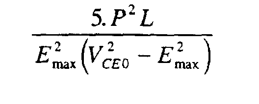
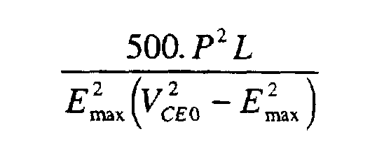
- the supply device according to the invention is characterized in that the capacity C of the capacitive filter is greater than: and less than:
- the invention consists in selecting a capacitor intended to serve input filter, whose capacity is much lower than that of commonly used capacitors.
- This operating mode results in an increase in current harmonics inside the motor, and therefore an increase in the effective value of this current for the same useful current value.
- the engine must be oversized compared to an engine operating from a constant voltage.
- the windings of copper and the rotor magnets must be larger than those of a motor operating from an equivalent constant voltage.
- the voltage inverter can adopt different architectures.
- it has two connected arms across the capacitive filter, each arm having two switches static in series.
- the voltage inverter has two arms connected to the terminals of the capacitive filter, each arm comprising a single static switch.
- the capacitor chosen is a polyester capacitor.
- the engine comprises a number of poles greater than or equal to four, and preferably equal to six.
- torque for the same flux value inside the motor, therefore torque, divide the phase inductance of the motor by the number of pairs of poles.
- the invention has an advantage, conversely, increase the number of pole pairs.
- the inductance of a winding is proportional to the square of its number of turns, while the flux traversed by the coil is proportional to the product of the number of turns by the current running through them.
- the invention relates to a power supply circuit for an engine such as for example a brushless electronic switching motor, especially intended for applications in the fields of household appliances, and in particular for electric vacuum cleaners.
- an engine such as for example a brushless electronic switching motor
- the diagram of a supply circuit is connected to AC network 1 typically with a value of 230 V effective
- the effective value of the network voltage can vary by around 10% around its nominal value. This therefore means that the maximum effective value can reach 253 V on an AC 230 V network, which corresponds to a maximum peak value E max of 358 V.
- the supply circuit therefore comprises a rectifier bridge 2, consisting of four diodes 3 arranged in accordance with FIG. 1.
- This rectifier bridge delivers a rectified voltage to the capacitive filter consisting of capacitor C.
- the voltage inverter 4 shown in FIG. 1 is connected to the terminals of the capacitive filter C, and comprises two identical arms, each having two transistors T 1 , T 2 , T 3 , T 4 , one of which is connected to the positive terminal of the capacitive filter, while the other is connected to the negative terminal of the capacitive filter.
- the bases of the transistors T 1 , T 2 , T 3 , T 4 are connected to the control circuit 8 which triggers their switching.
- Each of the transistors (T 1 -T 4 ) comprises a diode (D 1 -D 4 ) connected in antiparallel.
- each arm to which the two transistors (T 1 , T 2 , T 3 , T 4 ) are connected, is also connected to one of the terminals of the motor phase, modeled in Figure 1 by a inductance L, crossed by a current I L.
- each arm of the inverters are characterized by a maximum voltage value to which they must not be subjected at the risk of degradation or even destruction.
- this maximum voltage is generally known by the abbreviation of V CE0 corresponding to the maximum voltage between the collector and the emitter.
- the motor supplied by this voltage inverter is a "brushless" motor or a variable reluctance motor, whose nominal power P and phase inductance are required to determine the value of the capacitance C of the input filter, in accordance with the invention.
- the capacity of the input filter C is between the following two values: in which E max is the maximum peak voltage of the AC network, L is the inductance of a phase of the motor, P is the nominal power of the motor, and V CE0 is the maximum voltage to which the bipolar transistors can be subjected.
- the capacity of the DC voltage filter at C can be between 0.5 ⁇ F and 50 ⁇ F.
- the transistors T 1 and T 4 are controlled and the operation corresponds to what has already been described previously.
- the freewheeling diodes D 3 -D 2 or D 1 -D 4 are conductive, the input current of the inverter I e , with the sign convention corresponding to FIG. 1, is negative.
- the voltage illustrated in FIG. 2 has a component 15 at twice the network frequency, typically 100 Hz, corresponding to the value of the line voltage partially filtered by capacitor C.
- the inverter and therefore the motor does not work as very generally on a constant voltage, but well on a variable voltage.
- the motor is the seat of higher harmonic currents to those who cross it when it is supplied with constant voltage, since the peak and rms values deviate from the mean value. This induces a slight oversizing of the winding and the magnetized parts of the motor including the influence on the cost price is however offset by the low cost of capacitor chosen in accordance with the invention.
- FIG. 3 is an oscillogram representing, for a point of engine operation, the composition of the currents that produce the flux magnetic in the motor. There is a frequency beat due to the network frequency, phenomenon induced by the low value of the capacitor input, as previously explained.
- the motor used in the configuration according to the invention has a number of pairs of poles greater than or equal to two, and preferably equal to three.
- the use of a capacitive filter of relatively low value also limits the current harmonics injected on the AC power network, and allow the device equipped with the characteristic engine to respect the standards in force in particular concerning household appliances.
- the network voltage is 230 V, and can go up to 358 V peak.
- the selected inverter is equipped with bipolar transistors whose V CE0 is 600 V.
- the capacitor of the characteristic input filter is a polyester capacitor, with a capacity equal to 4.7 ⁇ F.
- the harmonic currents rejected on the network are much lower than the rates authorized by most standards governing harmonic rejection of household appliances.
- the invention is not limited to the voltage inverter structure described in detail above, but on the contrary covers the variants in which the inverter has a reduced number of static switches, as for example illustrated in Figure 5.
- the motor comprises two windings (B 1 , B 2 ) magnetically coupled according to the points shown and having a common terminal (e 1 , s 2 ).
- the inverter has two static switches (T 11 , T 12 ) each connected to a terminal (s 1 , e 2 ) of the winding different from the common terminal, also comprising diodes, respectively D 11 and D 22 mounted in antiparallel .
- a recovery circuit is made up of diodes D R1 , D R2 and impedance Z 2 .
- inverter structures can also be adopted, as long as the principle of the invention is respected, namely that the capacity of the filtering capacitor at the bridge output is such that the voltage across its terminals varies significantly during of the transfer of energy from the inductor to the capacitor during switching operations.
- the motor and its supply device according to the invention can present multiple applications, particularly in the field of household appliances, and more particularly in organ training rotating such as fans or turbines. So it finds a whole application natural in electric vacuum cleaners.
Landscapes
- Engineering & Computer Science (AREA)
- Power Engineering (AREA)
- Inverter Devices (AREA)
- Control Of Ac Motors In General (AREA)
- Electric Vacuum Cleaner (AREA)
- Manipulator (AREA)
- Nozzles For Electric Vacuum Cleaners (AREA)
Description
- d'un pont redresseur connecté au réseau de tension alternative ;
- d'un filtre capacitif connecté en sortie du pont redresseur, constitué d'au moins un condensateur de capacité C ;
- d'un onduleur de tension connecté aux bornes du filtre capacitif, et comportant au moins un interrupteur statique, chaque interrupteur étant apte à supporter une tension maximale VCE0 entre ses bornes ;
- d'un moteur à commutation électronique de puissance nominale P, et présentant une inductance de phase de valeur L.


Lorsque les diodes de roue libre D3-D2 ou D1-D4 sont conductrices, le courant d'entrée de l'onduleur Ie, avec la convention de signe correspondant à la figure 1, est négatif.
- la possibilité d'adopter un condensateur de filtrage continu appartenant à une gamme technologiquement moins coûteuse que les condensateurs électrolytiques habituellement utilisés pour ce genre de montage ;
- une commutation facilitée par une extinction rapide du courant dans la phase moteur, dans la phase de conduction ou diode de roue libre ;
- une faible réjection d'harmoniques de courant sur le réseau alternatif d'alimentation.
Claims (7)
- Ensemble moteur à commutation électronique, tel que notamment un moteur sans collecteur et dispositif d'alimentation dudit moteur à partir d'un réseau de tension alternative de tension crête maximale Emax, composé :caractérisé en ce que la capacité C du filtre capacitif est supérieure à :d'un pont redresseur (2) connecté au réseau de tension alternative ;d'un filtre capacitif connecté en sortie du pont redresseur, constitué d'au moins un condensateur de capacité C ;d'un onduleur de tension (4) connecté aux bornes du filtre capacitif (C), et comportant au moins un interrupteur statique (T1, T2, T3, T4), chaque interrupteur étant apte à supporter une tension maximale VCE0 entre ses bornes ;d'un moteur à commutation électronique de puissance nominale P, et présentant une inductance de phase de valeur L,et inférieure à :
- Ensemble selon la revendication 1, caractérisé en ce que l'onduleur de tension comporte deux bras connectés aux bornes du filtre capacitif (C), chaque bras comportant deux interrupteurs statiques (T1, T2, T3, T4) en série.
- Ensemble selon la revendication 1, caractérisé en ce que l'onduleur de tension comporte deux bras connectés aux bornes du filtre capacitif (C), chaque bras comportant un interrupteur statique.
- Ensemble selon l'une des revendications 1 à 3, caractérisé en ce que le condensateur est un condensateur polyester.
- Ensemble selon la revendication 1, caractérisé en ce que le moteur comporte un nombre de pôles supérieur ou égal à quatre.
- Ensemble selon la revendication 5, caractérisé en ce que le moteur comporte un nombre de pôles égal à six.
- Aspirateur électrique caractérisé en ce qu'il comporte un ensemble selon l'une des revendications 1 à 6.
Applications Claiming Priority (3)
| Application Number | Priority Date | Filing Date | Title |
|---|---|---|---|
| FR9912788A FR2799587B1 (fr) | 1999-10-08 | 1999-10-08 | Ensemble moteur electrique a commutation electronique, par exemple du type sans collecteur et dispositif d'alimentation dudit moteur, et aspirateur electrique equipe dudit ensemble |
| FR9912788 | 1999-10-08 | ||
| PCT/FR2000/002619 WO2001028083A1 (fr) | 1999-10-08 | 2000-09-21 | Ensemble moteur a commutation electrique, dispositif d'alimentation dudit moteur et aspirateur electrique equipe dudit ensemble |
Publications (2)
| Publication Number | Publication Date |
|---|---|
| EP1219012A1 EP1219012A1 (fr) | 2002-07-03 |
| EP1219012B1 true EP1219012B1 (fr) | 2003-04-23 |
Family
ID=9550897
Family Applications (1)
| Application Number | Title | Priority Date | Filing Date |
|---|---|---|---|
| EP00964341A Expired - Lifetime EP1219012B1 (fr) | 1999-10-08 | 2000-09-21 | Ensemble moteur a commutation electronique, dispositif d'alimentation dudit moteur et aspirateur electrique equipe dudit ensemble |
Country Status (6)
| Country | Link |
|---|---|
| EP (1) | EP1219012B1 (fr) |
| AT (1) | ATE238627T1 (fr) |
| AU (1) | AU7529700A (fr) |
| DE (1) | DE60002355T2 (fr) |
| FR (1) | FR2799587B1 (fr) |
| WO (1) | WO2001028083A1 (fr) |
Cited By (1)
| Publication number | Priority date | Publication date | Assignee | Title |
|---|---|---|---|---|
| EP2273669A1 (fr) | 2009-05-20 | 2011-01-12 | Miele & Cie. KG | Convertisseur de fréquence d'un moteur à réluctance commutée et système de mecatronique |
Families Citing this family (2)
| Publication number | Priority date | Publication date | Assignee | Title |
|---|---|---|---|---|
| GB2396491B (en) * | 2002-12-21 | 2005-11-30 | Dyson Ltd | Power conversion apparatus |
| GB2410847A (en) | 2004-02-05 | 2005-08-10 | Dyson Ltd | Control of motor winding energisation according to rotor angle |
Family Cites Families (3)
| Publication number | Priority date | Publication date | Assignee | Title |
|---|---|---|---|---|
| DE3010435A1 (de) * | 1980-03-19 | 1981-09-24 | Papst-Motoren Kg, 7742 St Georgen | Kollektorloser gleichstrommotor |
| JPH0279792A (ja) * | 1988-09-12 | 1990-03-20 | Secoh Giken Inc | 高速3相直流電動機 |
| JPH02294293A (ja) * | 1989-05-02 | 1990-12-05 | Secoh Giken Inc | 低電圧で駆動できるリラクタンス型電動機 |
-
1999
- 1999-10-08 FR FR9912788A patent/FR2799587B1/fr not_active Expired - Fee Related
-
2000
- 2000-09-21 AU AU75297/00A patent/AU7529700A/en not_active Abandoned
- 2000-09-21 WO PCT/FR2000/002619 patent/WO2001028083A1/fr not_active Ceased
- 2000-09-21 EP EP00964341A patent/EP1219012B1/fr not_active Expired - Lifetime
- 2000-09-21 DE DE60002355T patent/DE60002355T2/de not_active Expired - Lifetime
- 2000-09-21 AT AT00964341T patent/ATE238627T1/de not_active IP Right Cessation
Cited By (1)
| Publication number | Priority date | Publication date | Assignee | Title |
|---|---|---|---|---|
| EP2273669A1 (fr) | 2009-05-20 | 2011-01-12 | Miele & Cie. KG | Convertisseur de fréquence d'un moteur à réluctance commutée et système de mecatronique |
Also Published As
| Publication number | Publication date |
|---|---|
| WO2001028083A1 (fr) | 2001-04-19 |
| EP1219012A1 (fr) | 2002-07-03 |
| AU7529700A (en) | 2001-04-23 |
| FR2799587B1 (fr) | 2001-12-21 |
| DE60002355T2 (de) | 2004-02-12 |
| DE60002355D1 (de) | 2003-05-28 |
| FR2799587A1 (fr) | 2001-04-13 |
| ATE238627T1 (de) | 2003-05-15 |
Similar Documents
| Publication | Publication Date | Title |
|---|---|---|
| FR3037741A1 (fr) | Convertisseur a circuit correcteur du facteur de puissance | |
| CH694386A5 (fr) | Dispositif d'alimentation en courant à harmoniques diminués pour une charge recevant un courant alternatif polyphasé. | |
| FR2478896A1 (fr) | Moteur a courant continu sans collecteur | |
| EP1275196B1 (fr) | Moteur a angle d'avance de phase | |
| CH616784A5 (fr) | ||
| EP2822800A2 (fr) | Procede de decharge d'au moins un condensateur d'un circuit electrique | |
| WO2022171947A1 (fr) | Convertisseur modulaire multiniveaux pour application basse tension comprenant des branches de courant en mode de conduction discontinue | |
| EP2413485B1 (fr) | Système d'alimentation d'une charge en courant alternatif à partir d'un réseau alternatif sans présence d'un transformateur entre le réseau et le système d'alimentation, et chaîne d'entraînement comprenant un tel système | |
| EP1219012A1 (fr) | Ensemble moteur a commutation electronique, dispositif d'alimentation dudit moteur et aspirateur electrique equipe dudit ensemble | |
| EP0727866B1 (fr) | Dispositif de commande d'un moteur électrique à vitesse variable | |
| FR3106454A1 (fr) | Décharge de condensateur | |
| FR2911226A1 (fr) | Generateur et procede de generation de haute tension continue, depoussiereur utilisant ce generateur. | |
| EP0107539B1 (fr) | Circuit de commande d'un moteur synchrone à deux enroulements induits | |
| WO2012084389A2 (fr) | Convertisseur de puissance équipé en sortie d'un dispositif de filtrage | |
| EP3965299B1 (fr) | Dispositif de commande d'un thyristor | |
| WO2021038158A1 (fr) | Convertisseur modulaire multiniveaux pour application basse tension avec dimensionnement optimise des condensateurs | |
| EP0670628A1 (fr) | Dispositif d'alimentation pour moteur électrique à courant alternatif | |
| WO2001028082A1 (fr) | Ensemble moteur electrique sans collecteur, dispositif d'alimentation dudit moteur et aspirateur electrique equipe dudit ensemble | |
| EP2647112B1 (fr) | Variateur de vitesse equipe d'un dispositif de filtrage de mode commun | |
| EP0320560A1 (fr) | Dispositif moteur pour l'alimentation de véhicules et engins industriels | |
| FR2468248A1 (fr) | Circuit de supression de bruit pour moteur electrique commande par thyristors | |
| WO2021038155A1 (fr) | Convertisseur modulaire multiniveaux pour application basse tension avec inductances optimisees et un nombre de niveaux augmente | |
| CA2170317C (fr) | Procede de commande pour courant electrique bidirectionnel et onduleur de tension a commutation douce | |
| FR2717017A1 (fr) | Dispositif d'alimentation pour moteur électrique à courant alternatif. | |
| EP0101121B1 (fr) | Dispositifs statiques de conversion d'énergie électrique à semi-conducteurs |
Legal Events
| Date | Code | Title | Description |
|---|---|---|---|
| PUAI | Public reference made under article 153(3) epc to a published international application that has entered the european phase |
Free format text: ORIGINAL CODE: 0009012 |
|
| 17P | Request for examination filed |
Effective date: 20020319 |
|
| AK | Designated contracting states |
Kind code of ref document: A1 Designated state(s): AT BE CH CY DE DK ES FI FR GB GR IE IT LI LU MC NL PT SE |
|
| AX | Request for extension of the european patent |
Free format text: AL;LT;LV;MK;RO;SI |
|
| GRAH | Despatch of communication of intention to grant a patent |
Free format text: ORIGINAL CODE: EPIDOS IGRA |
|
| GRAH | Despatch of communication of intention to grant a patent |
Free format text: ORIGINAL CODE: EPIDOS IGRA |
|
| GRAA | (expected) grant |
Free format text: ORIGINAL CODE: 0009210 |
|
| AK | Designated contracting states |
Designated state(s): AT BE CH CY DE DK ES FI FR GB GR IE IT LI LU MC NL PT SE |
|
| PG25 | Lapsed in a contracting state [announced via postgrant information from national office to epo] |
Ref country code: IT Free format text: LAPSE BECAUSE OF FAILURE TO SUBMIT A TRANSLATION OF THE DESCRIPTION OR TO PAY THE FEE WITHIN THE PRESCRIBED TIME-LIMIT;WARNING: LAPSES OF ITALIAN PATENTS WITH EFFECTIVE DATE BEFORE 2007 MAY HAVE OCCURRED AT ANY TIME BEFORE 2007. THE CORRECT EFFECTIVE DATE MAY BE DIFFERENT FROM THE ONE RECORDED. Effective date: 20030423 Ref country code: FI Free format text: LAPSE BECAUSE OF FAILURE TO SUBMIT A TRANSLATION OF THE DESCRIPTION OR TO PAY THE FEE WITHIN THE PRESCRIBED TIME-LIMIT Effective date: 20030423 Ref country code: IE Free format text: LAPSE BECAUSE OF FAILURE TO SUBMIT A TRANSLATION OF THE DESCRIPTION OR TO PAY THE FEE WITHIN THE PRESCRIBED TIME-LIMIT Effective date: 20030423 Ref country code: GB Free format text: LAPSE BECAUSE OF FAILURE TO SUBMIT A TRANSLATION OF THE DESCRIPTION OR TO PAY THE FEE WITHIN THE PRESCRIBED TIME-LIMIT Effective date: 20030423 Ref country code: NL Free format text: LAPSE BECAUSE OF FAILURE TO SUBMIT A TRANSLATION OF THE DESCRIPTION OR TO PAY THE FEE WITHIN THE PRESCRIBED TIME-LIMIT Effective date: 20030423 Ref country code: AT Free format text: LAPSE BECAUSE OF FAILURE TO SUBMIT A TRANSLATION OF THE DESCRIPTION OR TO PAY THE FEE WITHIN THE PRESCRIBED TIME-LIMIT Effective date: 20030423 |
|
| REG | Reference to a national code |
Ref country code: GB Ref legal event code: FG4D Free format text: NOT ENGLISH |
|
| REG | Reference to a national code |
Ref country code: CH Ref legal event code: EP |
|
| PGFP | Annual fee paid to national office [announced via postgrant information from national office to epo] |
Ref country code: FR Payment date: 20030522 Year of fee payment: 4 |
|
| REF | Corresponds to: |
Ref document number: 60002355 Country of ref document: DE Date of ref document: 20030528 Kind code of ref document: P |
|
| REG | Reference to a national code |
Ref country code: IE Ref legal event code: FG4D Free format text: FRENCH |
|
| PG25 | Lapsed in a contracting state [announced via postgrant information from national office to epo] |
Ref country code: SE Free format text: LAPSE BECAUSE OF FAILURE TO SUBMIT A TRANSLATION OF THE DESCRIPTION OR TO PAY THE FEE WITHIN THE PRESCRIBED TIME-LIMIT Effective date: 20030723 Ref country code: DK Free format text: LAPSE BECAUSE OF FAILURE TO SUBMIT A TRANSLATION OF THE DESCRIPTION OR TO PAY THE FEE WITHIN THE PRESCRIBED TIME-LIMIT Effective date: 20030723 Ref country code: GR Free format text: LAPSE BECAUSE OF FAILURE TO SUBMIT A TRANSLATION OF THE DESCRIPTION OR TO PAY THE FEE WITHIN THE PRESCRIBED TIME-LIMIT Effective date: 20030723 Ref country code: PT Free format text: LAPSE BECAUSE OF FAILURE TO SUBMIT A TRANSLATION OF THE DESCRIPTION OR TO PAY THE FEE WITHIN THE PRESCRIBED TIME-LIMIT Effective date: 20030723 |
|
| PG25 | Lapsed in a contracting state [announced via postgrant information from national office to epo] |
Ref country code: LU Free format text: LAPSE BECAUSE OF NON-PAYMENT OF DUE FEES Effective date: 20030921 Ref country code: CY Free format text: LAPSE BECAUSE OF FAILURE TO SUBMIT A TRANSLATION OF THE DESCRIPTION OR TO PAY THE FEE WITHIN THE PRESCRIBED TIME-LIMIT Effective date: 20030921 |
|
| LTIE | Lt: invalidation of european patent or patent extension |
Effective date: 20030423 |
|
| PG25 | Lapsed in a contracting state [announced via postgrant information from national office to epo] |
Ref country code: BE Free format text: LAPSE BECAUSE OF NON-PAYMENT OF DUE FEES Effective date: 20030930 Ref country code: MC Free format text: LAPSE BECAUSE OF NON-PAYMENT OF DUE FEES Effective date: 20030930 |
|
| NLV1 | Nl: lapsed or annulled due to failure to fulfill the requirements of art. 29p and 29m of the patents act | ||
| GBV | Gb: ep patent (uk) treated as always having been void in accordance with gb section 77(7)/1977 [no translation filed] |
Effective date: 20030423 |
|
| PG25 | Lapsed in a contracting state [announced via postgrant information from national office to epo] |
Ref country code: ES Free format text: LAPSE BECAUSE OF FAILURE TO SUBMIT A TRANSLATION OF THE DESCRIPTION OR TO PAY THE FEE WITHIN THE PRESCRIBED TIME-LIMIT Effective date: 20031030 |
|
| REG | Reference to a national code |
Ref country code: IE Ref legal event code: FD4D Ref document number: 1219012E Country of ref document: IE |
|
| PLBE | No opposition filed within time limit |
Free format text: ORIGINAL CODE: 0009261 |
|
| STAA | Information on the status of an ep patent application or granted ep patent |
Free format text: STATUS: NO OPPOSITION FILED WITHIN TIME LIMIT |
|
| BERE | Be: lapsed |
Owner name: S.A. *SEB Effective date: 20030930 |
|
| 26N | No opposition filed |
Effective date: 20040126 |
|
| PG25 | Lapsed in a contracting state [announced via postgrant information from national office to epo] |
Ref country code: CH Free format text: LAPSE BECAUSE OF NON-PAYMENT OF DUE FEES Effective date: 20040930 Ref country code: LI Free format text: LAPSE BECAUSE OF NON-PAYMENT OF DUE FEES Effective date: 20040930 |
|
| REG | Reference to a national code |
Ref country code: CH Ref legal event code: PL |
|
| PG25 | Lapsed in a contracting state [announced via postgrant information from national office to epo] |
Ref country code: FR Free format text: LAPSE BECAUSE OF NON-PAYMENT OF DUE FEES Effective date: 20050531 |
|
| REG | Reference to a national code |
Ref country code: FR Ref legal event code: ST |
|
| PGFP | Annual fee paid to national office [announced via postgrant information from national office to epo] |
Ref country code: DE Payment date: 20150914 Year of fee payment: 16 |
|
| REG | Reference to a national code |
Ref country code: DE Ref legal event code: R119 Ref document number: 60002355 Country of ref document: DE |
|
| PG25 | Lapsed in a contracting state [announced via postgrant information from national office to epo] |
Ref country code: DE Free format text: LAPSE BECAUSE OF NON-PAYMENT OF DUE FEES Effective date: 20170401 |