EP1218318B1 - Gas generator and method for the generation of low-temperature gas - Google Patents
Gas generator and method for the generation of low-temperature gas Download PDFInfo
- Publication number
- EP1218318B1 EP1218318B1 EP00970317A EP00970317A EP1218318B1 EP 1218318 B1 EP1218318 B1 EP 1218318B1 EP 00970317 A EP00970317 A EP 00970317A EP 00970317 A EP00970317 A EP 00970317A EP 1218318 B1 EP1218318 B1 EP 1218318B1
- Authority
- EP
- European Patent Office
- Prior art keywords
- gas
- gas generator
- solid material
- generator according
- decomposition
- Prior art date
- Legal status (The legal status is an assumption and is not a legal conclusion. Google has not performed a legal analysis and makes no representation as to the accuracy of the status listed.)
- Expired - Lifetime
Links
- 238000000034 method Methods 0.000 title claims description 23
- 239000000159 acid neutralizing agent Substances 0.000 claims abstract description 23
- 239000007795 chemical reaction product Substances 0.000 claims abstract description 14
- 230000002123 temporal effect Effects 0.000 claims abstract description 7
- 239000007789 gas Substances 0.000 claims description 157
- IJGRMHOSHXDMSA-UHFFFAOYSA-N Atomic nitrogen Chemical compound N#N IJGRMHOSHXDMSA-UHFFFAOYSA-N 0.000 claims description 71
- 238000000354 decomposition reaction Methods 0.000 claims description 40
- NINIDFKCEFEMDL-UHFFFAOYSA-N Sulfur Chemical group [S] NINIDFKCEFEMDL-UHFFFAOYSA-N 0.000 claims description 39
- 239000005864 Sulphur Substances 0.000 claims description 38
- 229910052757 nitrogen Inorganic materials 0.000 claims description 33
- 239000011734 sodium Substances 0.000 claims description 29
- 239000011343 solid material Substances 0.000 claims description 28
- DGAQECJNVWCQMB-PUAWFVPOSA-M Ilexoside XXIX Chemical compound C[C@@H]1CC[C@@]2(CC[C@@]3(C(=CC[C@H]4[C@]3(CC[C@@H]5[C@@]4(CC[C@@H](C5(C)C)OS(=O)(=O)[O-])C)C)[C@@H]2[C@]1(C)O)C)C(=O)O[C@H]6[C@@H]([C@H]([C@@H]([C@H](O6)CO)O)O)O.[Na+] DGAQECJNVWCQMB-PUAWFVPOSA-M 0.000 claims description 27
- 229910052708 sodium Inorganic materials 0.000 claims description 27
- 230000003472 neutralizing effect Effects 0.000 claims description 26
- 239000002893 slag Substances 0.000 claims description 23
- PXIPVTKHYLBLMZ-UHFFFAOYSA-N Sodium azide Chemical compound [Na+].[N-]=[N+]=[N-] PXIPVTKHYLBLMZ-UHFFFAOYSA-N 0.000 claims description 22
- 238000006243 chemical reaction Methods 0.000 claims description 21
- 239000000203 mixture Substances 0.000 claims description 21
- 238000006386 neutralization reaction Methods 0.000 claims description 18
- 239000003795 chemical substances by application Substances 0.000 claims description 16
- 230000008569 process Effects 0.000 claims description 12
- 238000001816 cooling Methods 0.000 claims description 10
- 239000001257 hydrogen Substances 0.000 claims description 5
- 229910052739 hydrogen Inorganic materials 0.000 claims description 5
- UFHFLCQGNIYNRP-UHFFFAOYSA-N Hydrogen Chemical compound [H][H] UFHFLCQGNIYNRP-UHFFFAOYSA-N 0.000 claims description 4
- 239000011358 absorbing material Substances 0.000 claims description 4
- 150000001540 azides Chemical class 0.000 claims description 4
- QVGXLLKOCUKJST-UHFFFAOYSA-N atomic oxygen Chemical compound [O] QVGXLLKOCUKJST-UHFFFAOYSA-N 0.000 claims description 3
- 239000000356 contaminant Substances 0.000 claims description 3
- 239000001301 oxygen Substances 0.000 claims description 3
- 229910052760 oxygen Inorganic materials 0.000 claims description 3
- 238000001914 filtration Methods 0.000 claims 1
- 239000000463 material Substances 0.000 description 17
- 239000000047 product Substances 0.000 description 15
- 150000001875 compounds Chemical class 0.000 description 9
- 239000002826 coolant Substances 0.000 description 8
- 229910001873 dinitrogen Inorganic materials 0.000 description 6
- 239000000126 substance Substances 0.000 description 6
- VYPSYNLAJGMNEJ-UHFFFAOYSA-N Silicium dioxide Chemical compound O=[Si]=O VYPSYNLAJGMNEJ-UHFFFAOYSA-N 0.000 description 5
- GRVFOGOEDUUMBP-UHFFFAOYSA-N sodium sulfide (anhydrous) Chemical compound [Na+].[Na+].[S-2] GRVFOGOEDUUMBP-UHFFFAOYSA-N 0.000 description 5
- 230000007423 decrease Effects 0.000 description 3
- 230000000694 effects Effects 0.000 description 3
- XEEYBQQBJWHFJM-UHFFFAOYSA-N iron Substances [Fe] XEEYBQQBJWHFJM-UHFFFAOYSA-N 0.000 description 3
- 238000004519 manufacturing process Methods 0.000 description 3
- 239000011148 porous material Substances 0.000 description 3
- 239000004576 sand Substances 0.000 description 3
- 239000007787 solid Substances 0.000 description 3
- XTEGARKTQYYJKE-UHFFFAOYSA-M Chlorate Chemical class [O-]Cl(=O)=O XTEGARKTQYYJKE-UHFFFAOYSA-M 0.000 description 2
- UQSXHKLRYXJYBZ-UHFFFAOYSA-N Iron oxide Chemical compound [Fe]=O UQSXHKLRYXJYBZ-UHFFFAOYSA-N 0.000 description 2
- 229910000831 Steel Inorganic materials 0.000 description 2
- 230000004913 activation Effects 0.000 description 2
- 239000003513 alkali Substances 0.000 description 2
- 229910052783 alkali metal Inorganic materials 0.000 description 2
- 229910052796 boron Inorganic materials 0.000 description 2
- 230000006378 damage Effects 0.000 description 2
- 231100001261 hazardous Toxicity 0.000 description 2
- 238000010438 heat treatment Methods 0.000 description 2
- 150000004678 hydrides Chemical class 0.000 description 2
- 229910052742 iron Inorganic materials 0.000 description 2
- 229910052751 metal Inorganic materials 0.000 description 2
- 239000002184 metal Substances 0.000 description 2
- 229910044991 metal oxide Inorganic materials 0.000 description 2
- 150000004706 metal oxides Chemical class 0.000 description 2
- 229910052976 metal sulfide Inorganic materials 0.000 description 2
- 230000007935 neutral effect Effects 0.000 description 2
- 239000000843 powder Substances 0.000 description 2
- 150000003388 sodium compounds Chemical class 0.000 description 2
- 239000010959 steel Substances 0.000 description 2
- 241001323490 Colias gigantea Species 0.000 description 1
- MYMOFIZGZYHOMD-UHFFFAOYSA-N Dioxygen Chemical compound O=O MYMOFIZGZYHOMD-UHFFFAOYSA-N 0.000 description 1
- 238000010521 absorption reaction Methods 0.000 description 1
- 230000002411 adverse Effects 0.000 description 1
- 239000000443 aerosol Substances 0.000 description 1
- 150000001340 alkali metals Chemical group 0.000 description 1
- -1 alkalimetal azides Chemical class 0.000 description 1
- 239000003153 chemical reaction reagent Substances 0.000 description 1
- 229910052681 coesite Inorganic materials 0.000 description 1
- 238000010276 construction Methods 0.000 description 1
- 229910052802 copper Inorganic materials 0.000 description 1
- 229910052906 cristobalite Inorganic materials 0.000 description 1
- 230000003247 decreasing effect Effects 0.000 description 1
- 230000007812 deficiency Effects 0.000 description 1
- 229910001882 dioxygen Inorganic materials 0.000 description 1
- 238000004880 explosion Methods 0.000 description 1
- 239000002360 explosive Substances 0.000 description 1
- 238000009472 formulation Methods 0.000 description 1
- 239000008187 granular material Substances 0.000 description 1
- 239000000383 hazardous chemical Substances 0.000 description 1
- 150000002431 hydrogen Chemical class 0.000 description 1
- 238000009434 installation Methods 0.000 description 1
- 230000003993 interaction Effects 0.000 description 1
- 229910052749 magnesium Inorganic materials 0.000 description 1
- 230000007246 mechanism Effects 0.000 description 1
- QJGQUHMNIGDVPM-UHFFFAOYSA-N nitrogen(.) Chemical compound [N] QJGQUHMNIGDVPM-UHFFFAOYSA-N 0.000 description 1
- 239000002245 particle Substances 0.000 description 1
- 238000005192 partition Methods 0.000 description 1
- 239000005011 phenolic resin Substances 0.000 description 1
- 229920001568 phenolic resin Polymers 0.000 description 1
- TZLVRPLSVNESQC-UHFFFAOYSA-N potassium azide Chemical compound [K+].[N-]=[N+]=[N-] TZLVRPLSVNESQC-UHFFFAOYSA-N 0.000 description 1
- 239000003380 propellant Substances 0.000 description 1
- 230000009257 reactivity Effects 0.000 description 1
- 238000000926 separation method Methods 0.000 description 1
- 239000000377 silicon dioxide Substances 0.000 description 1
- 229910052979 sodium sulfide Inorganic materials 0.000 description 1
- 239000004449 solid propellant Substances 0.000 description 1
- 229910052682 stishovite Inorganic materials 0.000 description 1
- 229910052718 tin Inorganic materials 0.000 description 1
- 229910052719 titanium Inorganic materials 0.000 description 1
- 229910052905 tridymite Inorganic materials 0.000 description 1
- XLYOFNOQVPJJNP-UHFFFAOYSA-N water Substances O XLYOFNOQVPJJNP-UHFFFAOYSA-N 0.000 description 1
- 210000002268 wool Anatomy 0.000 description 1
Images
Classifications
-
- C—CHEMISTRY; METALLURGY
- C06—EXPLOSIVES; MATCHES
- C06B—EXPLOSIVES OR THERMIC COMPOSITIONS; MANUFACTURE THEREOF; USE OF SINGLE SUBSTANCES AS EXPLOSIVES
- C06B23/00—Compositions characterised by non-explosive or non-thermic constituents
- C06B23/04—Compositions characterised by non-explosive or non-thermic constituents for cooling the explosion gases including antifouling and flash suppressing agents
-
- C—CHEMISTRY; METALLURGY
- C06—EXPLOSIVES; MATCHES
- C06B—EXPLOSIVES OR THERMIC COMPOSITIONS; MANUFACTURE THEREOF; USE OF SINGLE SUBSTANCES AS EXPLOSIVES
- C06B23/00—Compositions characterised by non-explosive or non-thermic constituents
- C06B23/02—Compositions characterised by non-explosive or non-thermic constituents for neutralising poisonous gases from explosives produced during blasting
-
- C—CHEMISTRY; METALLURGY
- C06—EXPLOSIVES; MATCHES
- C06B—EXPLOSIVES OR THERMIC COMPOSITIONS; MANUFACTURE THEREOF; USE OF SINGLE SUBSTANCES AS EXPLOSIVES
- C06B45/00—Compositions or products which are defined by structure or arrangement of component of product
-
- C—CHEMISTRY; METALLURGY
- C06—EXPLOSIVES; MATCHES
- C06D—MEANS FOR GENERATING SMOKE OR MIST; GAS-ATTACK COMPOSITIONS; GENERATION OF GAS FOR BLASTING OR PROPULSION (CHEMICAL PART)
- C06D5/00—Generation of pressure gas, e.g. for blasting cartridges, starting cartridges, rockets
- C06D5/06—Generation of pressure gas, e.g. for blasting cartridges, starting cartridges, rockets by reaction of two or more solids
Definitions
- the invention relates to applied chemistry, more specifically to a composition for the generation of gases of low temperature and a process for the obtaining of gases of low temperature.
- Gas generating processes based on the decomposition or burning of chemical propellants and other compositions are frequently being used for a number of purposes such as the inflation of airbags from, for instance, cars, rafts, life boats and vests, fast installed partitions (which are used in well drifts to cut off the well in case of fire), drives and generators for different types of pneumatic systems and operations mechanisms etc.
- the hot gases generated from the decomposition of these materials are in general cooled with the aid of special chemical cooling agents or by specific designed features such as heat exchangers.
- the high temperature burning gases are passed through the layer of the cooling agent or the heat exchanger and the temperature of the gases decreases as a result of the endothermal decomposition process of, or heat absorption by the cooling agent.
- Such processes are described for instance in US-1362349 , GB-1371506 , FR-136897 and the Russian inventors certificate 801540 .
- the use of heat exchangers is described in GB-1500137 and GB-1487944 .
- the degree of cooling of the generated gas depends on the nature of the cooling agent, the mass of the cooling agent, which can sometimes exceeds the mass of the gas-generating composition, and in case of the heat exchanger, the design features of exchanger.
- gases obtained by the use of the above described methods contain large and undesired amounts of components which may not only have a negative effect on the construction but also in case of airbags for cars, for the person (driver) who is supposed to be protected by the airbag.
- RF-patent 2108282 describes a method of generating cold gases, specifically nitrogen, but also hydrogen and oxygen, by using the endothermal decomposition of a product made of gas penetrable solid material.
- the gas penetratable solid material comprises a gas source and a heat absorbing mixture, whereby the gaseous reaction products are cooled by passing the hot gases through the porous body of the product in the moving direction of the reaction front.
- the hot gases heat the porous body to a temperature necessary to support the endothermic chemical reaction taking place.
- the heating of the porous body is necessary to enable the main reaction.
- the decomposition of the cooling agent is also an endothermic chemical reaction.
- NaN 3 may be used for a nitrogen producing gas generator composition.
- the decomposition reaction of NaN 3 results in Na and N 2 .
- sodium is formed.
- the formed gas is blown off and the slag remains.
- This slag comprises of the remains of cementing agent and , the cooling agent and the metallic sodium.
- This highly reactive material will accumulate in the condensed burning decomposition products and thus provides a potential hazard for persons involved. When moisture is present this can result in vigorous and dangerous reactions taking place in combination with the generation of the highly flammable and explosive hydrogen.
- the decomposition of which might be followed by explosions, other undesirable effects or even personal injuries, if persons are involved.
- sodium-compounds as the gas source, elemental sodium (Na) is formed upon decomposition of sodiumazide.
- Sodium is a highly reactive and aggressive chemical. As a result of this reactivity, sodium can react with a wide class of substances to a number of sufficiently stable compounds.
- One of these compounds is sulphur. Sodium reacts with sulphur to form sodium sulphide (Na 2 S).
- the neutralisation of sodium by reaction with sulphur or sulphur compounds in gas generating compositions is known for instance from US 3775199 , US 5536340 , EP 394103 and US 3741585 .
- the sulphur is vaporised during the decomposition of the gas-generating composition and reacts with the formed sodium slag to the neutral sodiumsulphide.
- the invention accordingly comprises a gas generator comprising at least one first body, comprising means for the generation of gas and one or more reaction products at a decomposition front by decomposition of a gas-penetrable porous solid material in said first body, and at least one spatially separated second body, comprising means for the generation of a neutralisation agent, wherein means are present for passing said gas through the said first body and means are present for passing said neutralisation agent through the said decomposed gas-penetrable solid material, whereby the neutralising agent does not come into contact with the decomposing solid material, during or prior to decomposition thereof, to neutralise one ore more reaction products - such as slag - from the generation of gas in the said first body, and wherein means are present for operating the generation of a neutralisation agent in the second body at a spatial interval and optionally a temporal interval from the generation of gas in the first body.
- the principle of the invention encompasses the separation of gas generation material and neutralising material, thereby making it possible to improve the effectivity and reliability of the gas generation and neutralisation.
- two gas generating materials are present in one housing, spatially separated from each other.
- the first gas generator comprises a composition from which nitrogen, hydrogen and/or oxygen gas, preferably of low temperature can be obtained by the decomposition of a gas generating composition in the form of a gas penetrable solid material wherein the generated gaseous products are passed through the porous body in the direction of the moving decomposition front.
- the second gas generator (the neutraliser) is another composition generating a neutralising gas, preferably comprising a gas generating composition together with an effective neutraliser compound, for instance sulphur, iron oxide, metal sulphide, metal oxides (from Fe, Cu, Mg, Ti, Sn, B etc.), SiO 2 and the like.
- an effective neutraliser compound for instance sulphur, iron oxide, metal sulphide, metal oxides (from Fe, Cu, Mg, Ti, Sn, B etc.), SiO 2 and the like.
- an effective neutraliser compound for instance sulphur, iron oxide, metal sulphide, metal oxides (from Fe, Cu, Mg, Ti, Sn, B etc.), SiO 2 and the like.
- an effective neutraliser compound for instance sulphur, iron oxide, metal sulphide, metal oxides (from Fe, Cu, Mg, Ti, Sn, B etc.), SiO 2 and the like.
- the invention is based on the principle, that only after the material has been decomposed, the neutralising material is passed through the decomposed porous solid material, thereby neutralising the (usually hazardous) decomposition products (slag).
- the neutralising gas is generated at a rate and a manner that the effective neutralisation of slag is accomplished and the vaporous neutralising agent is not emitted.
- the neutralising agent such as vaporous sulphur, reacts with the reaction products (slag) from the first gas generator such that the these products are effectively neutralised.
- the invention thus relates to a first gas generator comprising a gas penetrable solid material comprising a nitrogen source, preferably an azide, more preferably sodiumazide, cementing agent and optionally a heat absorbing mixture, wherein the solid material has a porosity of 35-60 % and a second gas generator containing a neutraliser composition which contains sulphur and an additional nitrogen source.
- a nitrogen source preferably an azide, more preferably sodiumazide, cementing agent and optionally a heat absorbing mixture
- the solid material has a porosity of 35-60 %
- a second gas generator containing a neutraliser composition which contains sulphur and an additional nitrogen source.
- the gases to be generated can be selected from the group of nitrogen, oxygen and hydrogen, or combinations thereof. Generally azides, hydrides and chlorates are used for that, preferably in the alkali metal form.
- the gas to be produced is nitrogen
- the nitrogen sources in both the first and the second gas generator are selected from the group of alkalimetal azides or an earth-alkalimetal azides, preferably potassium azide or sodium azide, more preferably sodium azide.
- the first and second gas generator do not have to be physically separated from each other. In embodiments of the invention they can be placed in any position relative to each other, as long as the vaporised neutraliser of the second generator can come into contact with the slag from the first generator.
- the neutralisation takes place behind the reaction front of the decomposition reaction of the first gas generator.
- the spatial interval between the said reaction front of the first gas generator and production of the neutralising agent in the second gas generator is such that the reaction products of high temperature from the first gas generator stay behind, while the nitrogen gas is blown off.
- the neutralisation front lags behind the decomposition front and neutralises the said reaction products remaining behind.
- the rate at which the gas generating composition decomposes is different from the decomposition rate of the neutraliser charge.
- the decomposition of the gas generating composition and the neutraliser are started simultaneously.
- Metallic slag is formed, followed by the generation of vaporous neutraliser in the second generator, which neutralises the slag.
- the moment at which the neutraliser is activated lies later than the moment of activation of the gas generator.
- the activation, or ignition, of the two bodies can be done by any suitable means known in the art.
- a typical embodiment of the invention is as follows.
- a body consists essentially of two parts: the gas generator and the neutraliser.
- the gas generator will contain a porous solid material, containing a gas generating component such as sodiumazide, together with cementing agents (such as phenolic resins) and optionally cooling agents or other heat absorbing mixtures.
- the other part of the body is the neutraliser mass.
- the neutraliser contains the neutraliser (sulphur, iron, metal sulphides, metal oxide) and a gas generating component.
- the gas-generating component may be identical to the gas generating component in the first part, for instance sodiumazide.
- the neutraliser is activated and the neutralising reagent is vaporised; in the case of solid neutralising agents it may be brought in aerosol form.
- the neutraliser will react with the slag, resulting in non-hazardous or less hazardous materials, in the case of neutralising sodium with sulphur, resulting in the neutral sodiumsulphide.
- the amount of neutraliser is such that it is sufficient to effectively neutralise the slag formed in both the neutraliser and the gas generator and that only minimal or almost no vaporous neutraliser is blown off.
- the neutralisation product in order to facilitate the interaction between the sodium and the neutraliser compound (e.g. sulphur) it is preferred that the neutralisation product is in a form in which the reaction with the sodium slag is enhanced.
- the neutraliser can be mixed with the gas-generating compound in the form of powder, granules, etc.
- the combined amounts of the nitrogen sources in the first and second body comprises 50-80 wt.% drawn on the total weight of the gas generator and the amount of neutralisation agent in the second body 47-90 wt.% of neutralisation agent, drawn on the weight of the second body.
- the respective weight of the gas generator is measured in the absence of housing, external cooling aids, etc.
- the second body comprises between 17 and 35 wt.% of the gas generator according to the invention, drawn on the total weight of the gas generator.
- the second body (gas generator) contains 10 to 53 wt.% of the nitrogen source and 47 to 90 wt.% of neutralising agent.
- the second body (gas generator) contains 15 to 25 wt.%, more preferable 17 to 23 wt.% of nitrogen source and 75 to 85 wt.%, more preferable 77 to 83 wt.% of sulphur.
- the sulphur is in a particulate form, preferably in the form of small particles, more preferably in the form of sulphur powder.
- the relative amounts of sodium azide and sulphur are contained between the lower limit of sulphur which that is the amount of sulphur necessary for the neutralisation of the elemental sodium formed.
- the upper limit of sulphur is determined by the amount at which almost no vaporised sulphur will be blown off or the amount that is considered acceptable with respect to output gas purity.
- the rate at which the gas was generated was determined in order to provide for an optimal formulation together with the optional heat absorbing product and the neutraliser product.
- the ratio of the different components was chosen such that the required maximum discharge of vaporised sulphur and the stable burning of the material was obtained. It was found that a stable ignition and burning of the material was not possible if the concentration of the sulphur in the material was more than 90 wt.% of the combined weight of additional nitrogen source and sulphur (neutraliser mass).
- the concentration of sulphur was below 47 wt.% of said combined weight, the discharge of vaporised sulphur decreased below the desired level and the total (neutraliser mass)/(nitrogen source) ratio had to be increased in order to obtain the bonding of the elemental sodium in sufficiently high levels.
- the preferred mass ratio of the nitrogen source and the neutraliser is determined by the total neutralisation of sodium to sodium sulphide in the slag.
- the nitrogen source and the neutraliser, preferably sulphur are homogeneously mixed as part of the second body.
- the neutraliser product comprises sulphur and additional nitrogen source in an amount of 10-53 wt.% of the additional nitrogen source and 47-90 wt.% of sulphur, based on the combined weight thereof.
- the combined amount of the nitrogen source and sulphur, based on the total weight of the product is from 17 to 35 wt.%.
- the combined amount of the additional nitrogen source and the sulphur is less than 17 wt.%, the total neutralisation of sodium is insufficient because of lack of sulphur. In case the amount is above 35 wt.%, the vaporised sulphur will be blown off with the generated gas and thus the purity of the generated nitrogen gas decreases.
- the generated gas may contain some entrained contaminants. If these are un-desirable in the intended use of the generator, it may be advantageous to include additional downstream filter means. This may be any kind of filter, such as sand, chemical filters, metal wire filters and the like. In some instances it may also be advantageous to include some additional neutralising agent in the filter, thereby providing an additional safeguard against contaminants being blown out with the gas.
- the invention also relates to a process for the generation of gases, preferably nitrogen, comprising the steps of:
- the materials Upon ignition of the nitrogen source containing gas generating material and the neutralisation material, the materials start decomposing.
- the gaseous decomposition products of the nitrogen source pass through the ramified porous body in the moving direction of the reaction front and are cooled by transferring heat to the porous body.
- vaporised sulphur is generated and passed through the slag of the nitrogen source.
- a spatial and temporal interval between the reaction front of the nitrogen source and the reaction front of the neutraliser is provided.
- the reaction between the vaporised sulphur and the metallic sodium is exothermic. However, as there is a spatial and/or temporal interval between the gas generation and the neutralisation, this will not influence the temperature of the generated gas.
- This interval can be accomplished by a lower reaction rate of the neutraliser when compared to the reaction rate of the nitrogen source or by a suitable time delay. By this interval the vaporised sulphur is mainly generated after the sodium is formed, thus allowing for more optimal reaction conditions for both the generation of gas and the neutralisation of sodium.
- the interval can also be controlled by design related features such as the adjustment of the flow rates by a different form of the burning surface or by the non-simultaneous ignition of the nitrogen source and the neutraliser.
- the invention accordingly comprises a generator for low temperature gas.
- the generated gases are cooled by passing the gases through a porous body in the moving direction of the reaction front.
- heat is absorbed which is formed in the exothermic reaction by a heat absorbing material included in the porous body.
- the amount of heat generated in relation to the amount absorbed heat is such that the generated gas is cooled to a temperature below 150°C, preferably below 100°C.
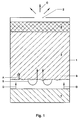
- a gas generator having a housing 1, provided with an opening 2, for generated gas.
- two gas generating bodies 3,4 are present.
- a body 5 of cooling and/or filter material is present, for example a sand filter, optionally containing a dispersed additional neutralising agent.
- the decomposition starts, resulting in the production of a gas, which flows mainly in the direction of the arrows B, i.e. through the body 3, thereby heating the porous material, at the same time as being cooled to a relatively low temperature. Finally the cooled gases leave the housing 1, through opening 2 in the direction of arrows C.
- the decomposition of the porous solid material proceeds with time and the decomposition front moves in the direction of arrow A.
- a neutralising gas is produced, after ignition of the body (by ignition means, not shown).
- the gas flows in the direction of arrows D and creates a neutralisation front (not shown) in body 3, which front stays behind the decomposition front, but moves in the same direction (arrow A).
Landscapes
- Chemical & Material Sciences (AREA)
- Organic Chemistry (AREA)
- Health & Medical Sciences (AREA)
- Chemical Kinetics & Catalysis (AREA)
- Engineering & Computer Science (AREA)
- Combustion & Propulsion (AREA)
- Crystallography & Structural Chemistry (AREA)
- Toxicology (AREA)
- Feeding, Discharge, Calcimining, Fusing, And Gas-Generation Devices (AREA)
- Air Bags (AREA)
- Diaphragms For Electromechanical Transducers (AREA)
- Treating Waste Gases (AREA)
- Sampling And Sample Adjustment (AREA)
- Gas Separation By Absorption (AREA)
Applications Claiming Priority (3)
| Application Number | Priority Date | Filing Date | Title |
|---|---|---|---|
| RU99120797 | 1999-09-30 | ||
| RU99120797/12A RU2250800C2 (ru) | 1999-09-30 | 1999-09-30 | Способ генерирования газов, предпочтительно азота, с низкой температурой и газогенератор для его осуществления |
| PCT/NL2000/000696 WO2001023327A1 (en) | 1999-09-30 | 2000-09-29 | Gas generator and method for the generation of low-temperature gas |
Publications (2)
| Publication Number | Publication Date |
|---|---|
| EP1218318A1 EP1218318A1 (en) | 2002-07-03 |
| EP1218318B1 true EP1218318B1 (en) | 2008-08-06 |
Family
ID=20225417
Family Applications (1)
| Application Number | Title | Priority Date | Filing Date |
|---|---|---|---|
| EP00970317A Expired - Lifetime EP1218318B1 (en) | 1999-09-30 | 2000-09-29 | Gas generator and method for the generation of low-temperature gas |
Country Status (11)
| Country | Link |
|---|---|
| US (1) | US20050199325A1 (https=) |
| EP (1) | EP1218318B1 (https=) |
| JP (1) | JP4596722B2 (https=) |
| CN (1) | CN1190393C (https=) |
| AT (1) | ATE403634T1 (https=) |
| AU (1) | AU775547B2 (https=) |
| BR (1) | BR0014426B1 (https=) |
| DE (1) | DE60039775D1 (https=) |
| NO (1) | NO321492B1 (https=) |
| RU (1) | RU2250800C2 (https=) |
| WO (1) | WO2001023327A1 (https=) |
Families Citing this family (12)
| Publication number | Priority date | Publication date | Assignee | Title |
|---|---|---|---|---|
| EP1151978A1 (en) * | 2000-05-02 | 2001-11-07 | Nederlandse Organisatie voor toegepast-natuurwetenschappelijk Onderzoek TNO | Process for generating a gas |
| EP1151976A1 (en) * | 2000-05-02 | 2001-11-07 | Nederlandse Organisatie Voor Toegepast-Natuurwetenschappelijk Onderzoek Tno | Process for inflating an object |
| EP1151977A1 (en) * | 2000-05-02 | 2001-11-07 | Nederlandse Organisatie voor toegepast-natuurwetenschappelijk Onderzoek TNO | Process for generating a gas for providing energy |
| EP1153903A1 (en) * | 2000-05-08 | 2001-11-14 | Nederlandse Organisatie voor toegepast-natuurwetenschappelijk Onderzoek TNO | Process for the generation of a gas |
| RU2302993C2 (ru) | 2001-07-26 | 2007-07-20 | Недерландсе Органисати Вор Тугепаст-Натюрветенсхаппелейк Ондерзук Тно | Химический кислородный генератор |
| US20070038175A1 (en) * | 2005-08-04 | 2007-02-15 | Kurt Daniel Van Laar | Enhanced needleless medication delivery system |
| US20060216337A1 (en) * | 2005-03-28 | 2006-09-28 | Van Laar Kurt D | Needeleless medication delivery system |
| RU2317283C1 (ru) * | 2006-05-29 | 2008-02-20 | Военная академия Ракетных войск стратегического назначения имени Петра Великого | Способ генерации низкотемпературного газа |
| EP2070870A1 (en) * | 2007-12-14 | 2009-06-17 | Nederlandse Organisatie voor toegepast- natuurwetenschappelijk onderzoek TNO | Formulation for generating nitrogen gas |
| CN103429556B (zh) * | 2011-02-07 | 2016-10-26 | 荷兰应用自然科技研究组织Tno | 化学二氧化碳气体发生器 |
| FR3012419B1 (fr) | 2013-10-25 | 2017-02-17 | Herakles | Procede et dispositif d'inertage d'une soute de fuel d'un aeronef |
| EP3901086A1 (en) | 2020-04-21 | 2021-10-27 | Nederlandse Organisatie voor toegepast- natuurwetenschappelijk Onderzoek TNO | Material and generator for generating hydrogen gas |
Family Cites Families (20)
| Publication number | Priority date | Publication date | Assignee | Title |
|---|---|---|---|---|
| US3741585A (en) * | 1971-06-29 | 1973-06-26 | Thiokol Chemical Corp | Low temperature nitrogen gas generating composition |
| US3985076A (en) * | 1973-11-19 | 1976-10-12 | Thiokol Corporation | Gas generator |
| DE3238465A1 (de) * | 1982-10-16 | 1984-05-03 | Erno Raumfahrttechnik Gmbh, 2800 Bremen | Stoffgemisch zur gaserzeugung |
| DE3316529A1 (de) * | 1982-10-16 | 1984-11-08 | Erno Raumfahrttechnik Gmbh, 2800 Bremen | Stoffgemisch zur gaserzeugung |
| US4630539A (en) * | 1985-06-24 | 1986-12-23 | The United States Of America As Represented By The Secretary Of The Army | Device for flash suppression of a rocket motor |
| IL76874A0 (en) * | 1985-10-29 | 1986-02-28 | Yeda Res & Dev | Source of nitrogen based on alkali metal azides |
| US4758287A (en) * | 1987-06-15 | 1988-07-19 | Talley Industries, Inc. | Porous propellant grain and method of making same |
| JPH0327782U (https=) * | 1989-07-28 | 1991-03-20 | ||
| DE3935869C1 (https=) * | 1989-10-27 | 1991-07-18 | Bayern-Chemie Gesellschaft Fuer Flugchemische Antriebe Mbh, 8261 Aschau, De | |
| EP0587900A4 (en) * | 1992-02-10 | 1995-09-27 | Daicel Chem | Linear gas generating agent and filter construction for gas generator |
| JPH0648880A (ja) * | 1992-06-05 | 1994-02-22 | Trw Inc | ガス発生器用の多層型ガス発生ディスク |
| US5495819A (en) * | 1994-03-09 | 1996-03-05 | Marion; Frank A. | Endothermic gas generator for use in a device propulsion |
| WO1996040541A1 (en) * | 1995-06-07 | 1996-12-19 | Takata Moses Lake, Inc. | Airbag inflator system |
| EP0767155B1 (en) * | 1995-10-06 | 2000-08-16 | Autoliv Asp, Inc. | Heterogeneous gas generant charges |
| US5868424A (en) * | 1996-03-06 | 1999-02-09 | Oea, Inc. | Substantially smoke-free and particulate-free inflator for inflatable safety restraint system |
| RU2108282C1 (ru) * | 1996-11-28 | 1998-04-10 | Научно-производственное объединение "Алтай" | Способ получения холодных газов и изделие для его осуществления |
| JPH10324219A (ja) * | 1997-03-26 | 1998-12-08 | Nippon Kayaku Co Ltd | ガス発生器 |
| EP0979219A1 (de) * | 1997-05-02 | 2000-02-16 | Dynamit Nobel GmbH Explosivstoff- und Systemtechnik | Reduzierung von schadgasen in gasgemischen aus pyrotechnischen reaktionen |
| WO1999010093A1 (fr) * | 1997-08-21 | 1999-03-04 | Nikolai Nikolaevich Sysoev | Procede de generation de gaz a basse temperature a partir de carburant solide |
| JPH11157412A (ja) * | 1997-11-28 | 1999-06-15 | Nippon Kayaku Co Ltd | ガス発生器 |
-
1999
- 1999-09-30 RU RU99120797/12A patent/RU2250800C2/ru active
-
2000
- 2000-09-29 CN CNB008136904A patent/CN1190393C/zh not_active Expired - Lifetime
- 2000-09-29 WO PCT/NL2000/000696 patent/WO2001023327A1/en not_active Ceased
- 2000-09-29 EP EP00970317A patent/EP1218318B1/en not_active Expired - Lifetime
- 2000-09-29 AT AT00970317T patent/ATE403634T1/de not_active IP Right Cessation
- 2000-09-29 BR BRPI0014426-6A patent/BR0014426B1/pt not_active IP Right Cessation
- 2000-09-29 DE DE60039775T patent/DE60039775D1/de not_active Expired - Lifetime
- 2000-09-29 JP JP2001526483A patent/JP4596722B2/ja not_active Expired - Lifetime
- 2000-09-29 AU AU79716/00A patent/AU775547B2/en not_active Expired
-
2002
- 2002-03-27 NO NO20021537A patent/NO321492B1/no not_active IP Right Cessation
-
2005
- 2005-04-25 US US11/113,904 patent/US20050199325A1/en not_active Abandoned
Also Published As
| Publication number | Publication date |
|---|---|
| BR0014426A (pt) | 2002-06-11 |
| CN1407958A (zh) | 2003-04-02 |
| NO321492B1 (no) | 2006-05-15 |
| EP1218318A1 (en) | 2002-07-03 |
| US20050199325A1 (en) | 2005-09-15 |
| RU2250800C2 (ru) | 2005-04-27 |
| AU775547B2 (en) | 2004-08-05 |
| ATE403634T1 (de) | 2008-08-15 |
| JP2003510228A (ja) | 2003-03-18 |
| WO2001023327A1 (en) | 2001-04-05 |
| BR0014426B1 (pt) | 2009-05-05 |
| AU7971600A (en) | 2001-04-30 |
| NO20021537L (no) | 2002-05-22 |
| DE60039775D1 (de) | 2008-09-18 |
| NO20021537D0 (no) | 2002-03-27 |
| JP4596722B2 (ja) | 2010-12-15 |
| CN1190393C (zh) | 2005-02-23 |
Similar Documents
| Publication | Publication Date | Title |
|---|---|---|
| EP0055904B1 (en) | Azide-free compositions for generating nitrogen, the generation of nitrogen therefrom and inflation of gas bags therewith | |
| US3785674A (en) | Crash restraint nitrogen generating inflation system | |
| US5542704A (en) | Automotive inflatable safety system propellant with complexing agent | |
| EP1218318B1 (en) | Gas generator and method for the generation of low-temperature gas | |
| EP0925808B1 (en) | Method of extinguishing a fire and a fire-extinguishing system | |
| US6605233B2 (en) | Gas generant composition with coolant | |
| US8142726B2 (en) | Cool oxygen chemical gas generator | |
| US20070102076A1 (en) | Gas-producing mixtures | |
| JPS646156B2 (https=) | ||
| JPH09508095A (ja) | ガス発生剤として用いる金属錯体 | |
| MXPA94009331A (en) | Generating composition of | |
| CA2708165C (en) | Formulation for generating nitrogen gas | |
| EP0012626B1 (en) | Method of and apparatus for gas generation | |
| US6589375B2 (en) | Low solids gas generant having a low flame temperature | |
| EP0844223B1 (en) | Gas-generating preparation and use thereof in an air bag | |
| KR20010041919A (ko) | 가스 발생기용 추진제 | |
| EP3901086A1 (en) | Material and generator for generating hydrogen gas | |
| RU2105750C1 (ru) | Газогенерирующий состав | |
| CN111918704A (zh) | 用于灭火的产生氮的组合物及其制备方法 | |
| Muhammed et al. | A review on gas-generants for application in exploding fire extinguisher balls | |
| WO2008108745A2 (en) | A nitroguanidine based gas generant containing mica | |
| JPH08151288A (ja) | エアバッグ用ガス発生剤 | |
| WO2001083402A1 (en) | Process for generating a gas |
Legal Events
| Date | Code | Title | Description |
|---|---|---|---|
| PUAI | Public reference made under article 153(3) epc to a published international application that has entered the european phase |
Free format text: ORIGINAL CODE: 0009012 |
|
| 17P | Request for examination filed |
Effective date: 20020402 |
|
| AK | Designated contracting states |
Kind code of ref document: A1 Designated state(s): AT BE CH CY DE DK ES FI FR GB GR IE IT LI LU MC NL PT SE |
|
| AX | Request for extension of the european patent |
Free format text: AL;LT;LV;MK;RO;SI |
|
| 17Q | First examination report despatched |
Effective date: 20040302 |
|
| GRAP | Despatch of communication of intention to grant a patent |
Free format text: ORIGINAL CODE: EPIDOSNIGR1 |
|
| GRAC | Information related to communication of intention to grant a patent modified |
Free format text: ORIGINAL CODE: EPIDOSCIGR1 |
|
| GRAS | Grant fee paid |
Free format text: ORIGINAL CODE: EPIDOSNIGR3 |
|
| GRAA | (expected) grant |
Free format text: ORIGINAL CODE: 0009210 |
|
| AK | Designated contracting states |
Kind code of ref document: B1 Designated state(s): AT BE CH CY DE DK ES FI FR GB GR IE IT LI LU MC NL PT SE |
|
| REG | Reference to a national code |
Ref country code: GB Ref legal event code: FG4D |
|
| REG | Reference to a national code |
Ref country code: CH Ref legal event code: EP |
|
| REG | Reference to a national code |
Ref country code: IE Ref legal event code: FG4D |
|
| REF | Corresponds to: |
Ref document number: 60039775 Country of ref document: DE Date of ref document: 20080918 Kind code of ref document: P |
|
| PG25 | Lapsed in a contracting state [announced via postgrant information from national office to epo] |
Ref country code: ES Free format text: LAPSE BECAUSE OF FAILURE TO SUBMIT A TRANSLATION OF THE DESCRIPTION OR TO PAY THE FEE WITHIN THE PRESCRIBED TIME-LIMIT Effective date: 20081117 |
|
| PG25 | Lapsed in a contracting state [announced via postgrant information from national office to epo] |
Ref country code: AT Free format text: LAPSE BECAUSE OF FAILURE TO SUBMIT A TRANSLATION OF THE DESCRIPTION OR TO PAY THE FEE WITHIN THE PRESCRIBED TIME-LIMIT Effective date: 20080806 Ref country code: FI Free format text: LAPSE BECAUSE OF FAILURE TO SUBMIT A TRANSLATION OF THE DESCRIPTION OR TO PAY THE FEE WITHIN THE PRESCRIBED TIME-LIMIT Effective date: 20080806 |
|
| PG25 | Lapsed in a contracting state [announced via postgrant information from national office to epo] |
Ref country code: BE Free format text: LAPSE BECAUSE OF FAILURE TO SUBMIT A TRANSLATION OF THE DESCRIPTION OR TO PAY THE FEE WITHIN THE PRESCRIBED TIME-LIMIT Effective date: 20080806 |
|
| PG25 | Lapsed in a contracting state [announced via postgrant information from national office to epo] |
Ref country code: DK Free format text: LAPSE BECAUSE OF FAILURE TO SUBMIT A TRANSLATION OF THE DESCRIPTION OR TO PAY THE FEE WITHIN THE PRESCRIBED TIME-LIMIT Effective date: 20080806 Ref country code: MC Free format text: LAPSE BECAUSE OF NON-PAYMENT OF DUE FEES Effective date: 20080930 |
|
| REG | Reference to a national code |
Ref country code: CH Ref legal event code: PL |
|
| PG25 | Lapsed in a contracting state [announced via postgrant information from national office to epo] |
Ref country code: PT Free format text: LAPSE BECAUSE OF FAILURE TO SUBMIT A TRANSLATION OF THE DESCRIPTION OR TO PAY THE FEE WITHIN THE PRESCRIBED TIME-LIMIT Effective date: 20090106 |
|
| PLBE | No opposition filed within time limit |
Free format text: ORIGINAL CODE: 0009261 |
|
| STAA | Information on the status of an ep patent application or granted ep patent |
Free format text: STATUS: NO OPPOSITION FILED WITHIN TIME LIMIT |
|
| REG | Reference to a national code |
Ref country code: IE Ref legal event code: MM4A |
|
| 26N | No opposition filed |
Effective date: 20090507 |
|
| PG25 | Lapsed in a contracting state [announced via postgrant information from national office to epo] |
Ref country code: IE Free format text: LAPSE BECAUSE OF NON-PAYMENT OF DUE FEES Effective date: 20080929 |
|
| PG25 | Lapsed in a contracting state [announced via postgrant information from national office to epo] |
Ref country code: LI Free format text: LAPSE BECAUSE OF NON-PAYMENT OF DUE FEES Effective date: 20080930 Ref country code: CH Free format text: LAPSE BECAUSE OF NON-PAYMENT OF DUE FEES Effective date: 20080930 |
|
| PG25 | Lapsed in a contracting state [announced via postgrant information from national office to epo] |
Ref country code: SE Free format text: LAPSE BECAUSE OF FAILURE TO SUBMIT A TRANSLATION OF THE DESCRIPTION OR TO PAY THE FEE WITHIN THE PRESCRIBED TIME-LIMIT Effective date: 20081106 |
|
| PG25 | Lapsed in a contracting state [announced via postgrant information from national office to epo] |
Ref country code: LU Free format text: LAPSE BECAUSE OF NON-PAYMENT OF DUE FEES Effective date: 20080929 Ref country code: CY Free format text: LAPSE BECAUSE OF FAILURE TO SUBMIT A TRANSLATION OF THE DESCRIPTION OR TO PAY THE FEE WITHIN THE PRESCRIBED TIME-LIMIT Effective date: 20080806 |
|
| PG25 | Lapsed in a contracting state [announced via postgrant information from national office to epo] |
Ref country code: GR Free format text: LAPSE BECAUSE OF FAILURE TO SUBMIT A TRANSLATION OF THE DESCRIPTION OR TO PAY THE FEE WITHIN THE PRESCRIBED TIME-LIMIT Effective date: 20081107 |
|
| REG | Reference to a national code |
Ref country code: FR Ref legal event code: PLFP Year of fee payment: 17 |
|
| REG | Reference to a national code |
Ref country code: FR Ref legal event code: PLFP Year of fee payment: 18 |
|
| REG | Reference to a national code |
Ref country code: FR Ref legal event code: PLFP Year of fee payment: 19 |
|
| PGFP | Annual fee paid to national office [announced via postgrant information from national office to epo] |
Ref country code: DE Payment date: 20190918 Year of fee payment: 20 Ref country code: IT Payment date: 20190925 Year of fee payment: 20 Ref country code: NL Payment date: 20190918 Year of fee payment: 20 Ref country code: FR Payment date: 20190925 Year of fee payment: 20 |
|
| PGFP | Annual fee paid to national office [announced via postgrant information from national office to epo] |
Ref country code: GB Payment date: 20190920 Year of fee payment: 20 |
|
| REG | Reference to a national code |
Ref country code: DE Ref legal event code: R071 Ref document number: 60039775 Country of ref document: DE |
|
| REG | Reference to a national code |
Ref country code: NL Ref legal event code: MK Effective date: 20200928 |
|
| REG | Reference to a national code |
Ref country code: GB Ref legal event code: PE20 Expiry date: 20200928 |
|
| PG25 | Lapsed in a contracting state [announced via postgrant information from national office to epo] |
Ref country code: GB Free format text: LAPSE BECAUSE OF EXPIRATION OF PROTECTION Effective date: 20200928 |