EP1218287B1 - Beweglicher ladearm mit ausgleich durch federn - Google Patents
Beweglicher ladearm mit ausgleich durch federn Download PDFInfo
- Publication number
- EP1218287B1 EP1218287B1 EP00949534A EP00949534A EP1218287B1 EP 1218287 B1 EP1218287 B1 EP 1218287B1 EP 00949534 A EP00949534 A EP 00949534A EP 00949534 A EP00949534 A EP 00949534A EP 1218287 B1 EP1218287 B1 EP 1218287B1
- Authority
- EP
- European Patent Office
- Prior art keywords
- spring
- section
- axis
- mobile
- balancing device
- Prior art date
- Legal status (The legal status is an assumption and is not a legal conclusion. Google has not performed a legal analysis and makes no representation as to the accuracy of the status listed.)
- Expired - Lifetime
Links
Images


Classifications
-
- B—PERFORMING OPERATIONS; TRANSPORTING
- B67—OPENING, CLOSING OR CLEANING BOTTLES, JARS OR SIMILAR CONTAINERS; LIQUID HANDLING
- B67D—DISPENSING, DELIVERING OR TRANSFERRING LIQUIDS, NOT OTHERWISE PROVIDED FOR
- B67D7/00—Apparatus or devices for transferring liquids from bulk storage containers or reservoirs into vehicles or into portable containers, e.g. for retail sale purposes
- B67D7/002—Apparatus or devices for transferring liquids from bulk storage containers or reservoirs into vehicles or into portable containers, e.g. for retail sale purposes using articulated pipes
-
- B—PERFORMING OPERATIONS; TRANSPORTING
- B67—OPENING, CLOSING OR CLEANING BOTTLES, JARS OR SIMILAR CONTAINERS; LIQUID HANDLING
- B67D—DISPENSING, DELIVERING OR TRANSFERRING LIQUIDS, NOT OTHERWISE PROVIDED FOR
- B67D9/00—Apparatus or devices for transferring liquids when loading or unloading ships
- B67D9/02—Apparatus or devices for transferring liquids when loading or unloading ships using articulated pipes
Definitions
- the invention relates to the transfer of fluid, liquid or gas, between a base and a mobile tank, for example a tank boarded a truck or railroad car.
- Fluid products can be of very varied types, for example but not limited to petroleum products, such as petrol or gas notably liquefied petroleum (LPG), or chemicals, acids or solvents in particular.
- petroleum products such as petrol or gas notably liquefied petroleum (LPG), or chemicals, acids or solvents in particular.
- LPG liquefied petroleum
- these fluid products are mainly liquid, but are generally in equilibrium with a gas phase, so that, rather than talking about liquid products, it's more accurate to talk about products fluids; sometimes it is necessary to transfer these two phases separately liquid and gaseous.
- connection between the base, on the one hand, and the flange connection of the mobile tank, on the other hand can only be achieved by a device with a certain deformation capacity.
- the devices transfer of fluid products often called transfer arms or loading / unloading, are thus of two possible types: either they have a flexible part, which poses possible problems of resistance to aging, either they consist of a succession of at least two tubular sections articulated to each other.
- the fluid transfer arms must therefore, in practice, be brought into an appropriate configuration when preparing a transfer operation, so as to bring a free end of this arm (the other end being generally permanently connected to the base) opposite of the connection flange of the tank concerned.
- This operation is generally performed by an operator, and it is desirable that the operator or not be forced to make too much effort.
- a motorized control of a liquid product transfer arm which avoids all effort to operators, however, is difficult to implement, given the difficulty of automatically bringing the free end of the arm opposite precisely from the connection flange; that supposes a great mastery of the arm configuration control automaton, and therefore training possibly long and costly for the operator. In any event, a such motorized control involves significant costs.
- a first category of balancing device uses one or several counterweights which are fixed opposite the arm part to be balanced. This solution, quite effective, is nevertheless cumbersome in the convenient.
- balancing device involves springs, for example steel torsion springs, in cylindrical helix the more often, attached to or inside the rotating joint; he can too they are torsion springs in steel in Archimedes spiral or in spiral hyperbolic. These devices can be illustrated by US-A-4,537,233.
- balancing device uses a spring steel compression, often located along the part of the arm to be balanced or in a device called balancing box or spring box, fixed on the part of arm to be balanced (see for example US-A-3,086,552).
- Yet another category of balancing device uses steel tension springs often also located along the arm.
- balancing device uses jacks, for example nitrogen, pneumatic, hydraulic, or electric.
- the object of the invention is to overcome the aforementioned drawbacks.
- an articulated product transfer arm fluids, liquids or gases comprising: two tubular sections connected one to the other by a rotary joint of horizontal axis, and one of which, movable in rotation around this horizontal axis, has a reference angular configuration in which it is in balance despite gravity; and a balancing device for compensate for variations in the effect of gravity on this mobile tubular section according to the orientation of the latter with respect to the vertical, characterized in that that this balancing device is mounted between a fixed reference portion by relative to the axis of rotation of the rotary joint and a connecting portion of the section mobile tubular which is at a constant non-zero distance from the axis of rotation, and includes a spring tending to return the movable section to its configuration angular reference, this spring being designed and mounted so as to apply to the movable tubular section, directly or indirectly, a force substantially proportional and substantially parallel to the distance between this portion of bond and the location in which this bond portion comes when the movable section is in its
- the other section is of fixed orientation by relative to the axis of the rotary joint (it is common in practice that this is the section connected to the fixed base), and the fixed reference portion to which the balancing device is connected at one of its ends is integral with this fixed section. This minimizes the size of the device balancing.
- the balancing device is connected to this fixed reference portion and to the connecting portion of the movable section by joints of horizontal axes which, when the balancing device is not not flexible, minimizes parasitic torques around the joint rotation axis turning.
- Another interesting case in which there is only one joint, for example between the spring and the movable section, and a rigid connection.
- the fixed portion is substantially opposite, parallel to the axis of rotation, from the location where the link portion of the section comes from mobile tubular, when the latter is in its reference configuration. it contributes to approaching a very good linearity of the spring as a function of the angular amplitude of rotation of the section to be balanced. Indeed, during the rotation of the tubular section to be balanced, the distance to the axis (lever arm) of the return force applied by the spring varies in the same way as the distance to the weight axis.
- the device balancing in the form of a loop, located in a plane substantially perpendicular to the axis of rotation and elastically deformable in this plane, and has two ends which are, in the rest configuration of this spring, one with the other.
- the spring comprises: a U-shaped piece forming a spring, elastically flexible in the plane of the loop, and having two branches connected by a curved portion; and two attachment tabs extending these branches to the ends of this balancing device.
- the spring advantageously comprises a single loop, for the sake of simplicity, but that, if we admit a more large size parallel to the axis of rotation, we can choose springs with several loops or turns (this can give more low stiffness, when desired.
- a spring having a general U-shape within a device for balancing any conception.
- it can also be a device in which one of the ends of the spring is connected to the connecting portion of the movable section by a belt passing over a pulley located parallel to the axis of rotation, opposite the location in which the portion is located of connection of the mobile tubular section when the latter is in the configuration of reference.
- the spring can also be a compression spring of traction located between a portion of a cylinder linked to the fixed section and a connected piston to this belt and mounted in this cylinder.
- the branches of the spring are solicited in one direction throughout the travel of the movable section, preferably in the direction corresponding to a reconciliation (we sometimes speak of "compression" of the branch spring).
- Figures 1 to 3 partially show a transfer arm fluid, liquid or gaseous products, comprising a first tubular section 1 (in fixed practice, fixed to a base), a second tubular section 2, a joint turning 3 with a horizontal axis, and a balancing device 4 connected to each of the tubular sections to compensate for variations in torque (due to the gravity) around the axis of the rotary joint during a relative rotation between the sections around this horizontal axis.
- the first tubular section 1 is vertical and is connected to a second rotating joint 6 with a vertical axis.
- This second seal turn 6 is in turn connected to the rotary joint 3 of horizontal axis by an elbow at right angles 7.
- This second tubular section 2 in the configuration shown in Figures 1 and 2, horizontal.
- This second tubular section 2 is ends at its left end with a third 90 ° elbow marked 8 which is connected to the rotary joint 3.
- the second tubular section 2 can take any orientation angular (inside of course of a given clearance), as well in azimuth only in elevation, relative to the first tubular section 1.
- elbow 7 which is connected to each of the rotary joints 3 and 6 in itself constitutes a tubular section, which is connected to the second tubular section 2 by a rotary joint with a horizontal axis.
- the balancing device 4 is connected to each of these sections tubular 2 and 7. It is therefore indirectly that this balancing device is connected to the tubular section 1, but, insofar as the rotary joint 6 has a vertical axis, no balancing effort is necessary to take into account variations in angular position during rotation of this rotating joint.
- This balancing device essentially consists of a spring 10, here generally U-shaped, having two branches 11 and 12, here parallel to each other in the spring rest configuration, and the ends of which 11A and 12A are each connected to one, respectively, of sections 2 and 7 by fastening lugs 15 and 16.
- each of the ends 15A and 16A of these fastening tabs is articulated on its respective section, around an axis parallel to the axis of the rotary joint.
- the pins 13 and 14 are advantageously facing each other parallel to the axis of the joint turning, i.e. are at least approximately in the extension one of the other.
- the ends 15A and 16A of the attachment tabs are arranged one next to the other, preferably one next to the other, in so that the housings are concentric.
- the ends of the branches of the spring can include a plurality of housings for receiving a member intended to its connection to the respective tubular section, for example the pin 13 or 14 supra.
- the attachment tabs 15 and 16 are, in the example of FIG. 4, reported at the ends of the branches of the spring 10, on the internal side of them.
- One and / or the other of the blocks 15 and 16 can be fixed outside the spring.
- the spring marked 10 ' (and so the balancing device of which it is the essential part) has the form of a loop, located in a plane substantially perpendicular to the axis of rotation of the Turning joint.
- This loop is here formed of a single piece whose ends are arranged side by side (see Figure 6).
- the two tubular sections 7 and 8 + 2 connected by the rotating joint horizontal axis marked 3 are each provided on either side with this seal rotating, of fastening pads 20 and 21 carrying the pins 13 and 14. These are advantageously shaped so that the spring is substantially arranged in a plane perpendicular to the axis of the rotary joint, that is to say in a vertical plane perpendicular to the plane of Figure 2, or in a parallel plane in the plan of figure 1.
- these studs can thus be consisting, as regards the tab 20, of two plates 20A and 20B angled and carrying a plate 20C carrying the pin 13 thus that, advantageously, a stop 22 for the spring or its legs attachment .
- the other attachment tab 21 it is constituted a collar 23 enclosing a portion of the movable tubular section 2 and carrying the pin 14.
- the stud 20 can be attached to a portion of the elbow 8 located in the immediate vicinity of the joint turning 3.
- the spring is advantageously made of a composite material. he these are for example glass fibers or carbon coated with resin and tooling (mold) to obtain the final U shape in the oven.
- the spring after baking goes into the finishing phase, by deburring, finishing, drilling, installation of a possible silicone finishing sheath (or other subject to market availability).
- this spring is advantageously coated with a silicone sheath able to effectively protect the material of the U-shaped part from various external attacks.
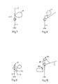
- Figures 7 to 9 show schematically the principle of balancing a device according to the invention.
- the spring In the configuration of natural balance (vertical section in Figure 7) the spring is in configuration of rest, its ends being substantially superimposed parallel to the axis remote rotation of it.
- section 2 to be balanced is inclined to the right, the branches of the spring begin to cross (we say that the spring compresses) and a return force is applied by the spring to a distance from the axis which depends on this inclination; we can however show that the variations of this distance are similar to the variations of the distance to the axis of the weight on this section 2. This property is preserved over a large range, up to a configuration inclined towards the bottom of the section (see figure 9).
- Figure 10 shows a configuration with the same properties, but in which the spring 10 (without the attachment tabs) is mounted between a fixed reference portion 100, preferably by articulation, and the end of a belt 101, passing through a pulley 102 and connected at its other end at a point in the section 2 which comes opposite the location of the pulley 102 in the natural equilibrium configuration of this section.
- the location of the pin 14 on the section is substantially oriented so as to intercept the axis longitudinal of this section, but this location in relation to the section is any, as long as the spring attachment point (or the location of the pulley) is opposite this journal in a natural balance configuration.
- the invention thus leads to a much more efficient balancing than the simple assistance provided by known devices while being simple, reliable and inexpensive.
- the balancing obtained is indeed very close to very good balancing achieved by counterweights but which has been previously said that they led to annoying congestion during maneuvers.
- the balancing device proposed by the invention is shown on a large scale. However, it should be noted that compared to an entire liquid product transfer arm, which may include several sections, and only a part of which is shown in FIGS. 1 to 3, the invention leads to a much smaller footprint than in the solutions known.
- the balancing proposed by the invention does not provide of overload on the part to be balanced, by comparison with a box spring.
- the balancing device proposed above allows, in a travel of 35 ° above and 85 ° below the horizontal reference position, almost perfect arm balancing (at less than 1 kg in absolute value).
- the weight of this spring is much less than all of the known balancing systems.
- this spring cannot break when the arm falls under its own weight as can be seen during even when adding heavy overloads to the arm: this spring can be deteriorate but not to the point of dropping the load suddenly.
- stops can be provided to limit the approximation (or even the spacing) of the branches of the spring.
- the spring is stressed in one direction (compression); of course in a variant not shown, it can only be used in traction.
- the attachment of the proposed device is simple to implement and does not requires no special tools.
- the device described above has been shown to be insensitive to variations of usual climatic temperatures. It is also, by design (notably due to the composite nature of the U-shaped part) not very sensitive to ultraviolet rays. No protective paint is therefore necessary.
- the balancing device of the invention very significantly reduces the need for spare parts.
- this assembly can be used with several springs mounted in parallel, thus obtaining a moment balancing.
- FIG. 11 partially shows a transfer arm comprising a first section 51 (in fixed practice) fixed to a base, a second section tubular 52, a rotary joint 53 with a horizontal axis, and a balancing device 54.
- This transfer arm is similar to that of FIGS. 1 to 3 and of analogous elements of this arm are designated by numbers derived from those of FIGS. 1 to 3 by adding the number 50.
- first section 51 is connected to a second rotating joint 56 with a vertical axis, itself connected to the rotary joint 53 by an elbow 57 at an angle law.
- the balancing device 54 is connected to each of the sections tubular 52 and 57. It essentially consists of a spring 60 having two branches 61 and 62 whose ends 61A and 62A are each connected to one, respectively, sections 52 and 57 by lugs 65 and 66.
- the end 65A connected to the section mobile, which is articulated at 64 on the tab 71 of this mobile section, while the end 66A, connected to the fixed section, is integral with the latter.
- the fastening tab 66 can constitute both the tabs of attachment of the spring, and of the fixed section.
- it is the end 66A which can be rigidly linked to its section.
- the end 62A of the spring is thus locked in an orientation predetermined, which is preferably the one it would take when the spring is at rest, the mobile section being in its reference configuration.
- the spring 60, its fastening tab 65 and the tab 71 are shown in a working configuration.
- this figure 11 appears further, in dashed, the rest configuration of these elements; we observe that the joint 64 of the fastening tab 65 is then, preferably, facing the tab fixed attachment 66.
- FIG. 12 shows another transfer arm, in accordance with block diagram of Figure 10, except for the structure of the spring used.
- the arm has a vertical section 81 connected by a seal 86 to an elbow 87 connected, by a joint 83 of horizontal axis to a movable section 82.
- the balancing device 84 comprises a spring system 90 connected, here by a rod 91, to a cable 92 passing over a return element 93, such than a pulley, and connected at 94 on the movable section.
- This attachment area 94 is preferably opposite the return element in the configuration balance of the mobile section.
- the spring system 90 comprises a cylinder 90A, integral with the section 81 (and therefore axially fixed relative to the intermediate section 87 on which the movable section is articulated) and a piston 90B, axially movable in this cylinder against a spring 90C compression.
- the rod is here integral with this piston.
- Figure 12 shows an intermediate configuration; the spring is at rest in the configuration balance of section 82.
- the cylinder is connected to this section 81 by rotary collars 81A allowing this cylinder to follow the rotation of the section 87.
- this cylinder is fixed on this section 87.
- the spring is designed and mounted in kind of applying to the movable tubular section (in a position located at a non-zero constant distance from the horizontal axis of rotation), directly or indirectly (for example by a cable), a force appreciably proportional and substantially parallel to the distance between the position instant of this portion of the movable tubular section and the location in which comes this portion when the movable tubular section is in its reference angular configuration (natural balance without spring action).
Landscapes
- Engineering & Computer Science (AREA)
- Mechanical Engineering (AREA)
- Manipulator (AREA)
- Apparatus For Radiation Diagnosis (AREA)
- Automobile Manufacture Line, Endless Track Vehicle, Trailer (AREA)
Claims (13)
- Arm für eine Übertragung von flüssigen oder gasförmigen fluiden Produkten, welcher angelenkt ist, aufweisend: zwei Rohrstücke (7, 8 + 2), welche miteinander durch eine Drehkupplung (3) einer horizontalen Achse verbunden sind, und von denen das eine, das beweglich in Drehung um diese horizontale Achse ist, eine winkelmäßige Referenzkonfiguration aufweist, in welcher es trotz der Schwerkraft im Gleichgewicht ist; und eine Gleichgewichtseinrichtung (4, 10) zum Kompensieren von Veränderungen einer Wirkung der Schwerkraft auf dieses bewegliche Rohrstück in Abhängigkeit von der Ausrichtung von diesem hinsichtlich der Vertikalen, dadurch gekennzeichnet, dass die Gleichgewichtseinrichtung zwischen einem Referenzabschnitt, der fest in Bezug auf die Drehachse der Drehkopplung ist, und einem Verbindungsabschnitt des beweglichen Rohstücks, welcher in einem konstanten Abstand, der nicht Null ist, von der Drehachse vorgesehen ist, montiert ist, und eine Feder (10) aufweist, welche gespannt ist, den beweglichen Abschnitt in seine winkelmäßige Referenzkonfiguration zurückzubringen, wobei diese Feder in einer Weise vorgesehen und montiert ist, auf das bewegliche Rohrstück direkt oder indirekt eine Kraft im Wesentlichen proportional und im Wesentlichen parallel zu dem Abstand zwischen diesem Verbindungsabschnitt und der Stelle, in welche dieser Verbindungsabschnitt gelangt, wenn das bewegliche Stück in seiner winkelmäßigen Referenzkonfiguration ist, anzulegen, wobei diese Feder in einer Ruhestellung ist, wenn das bewegliche Stück in einer Gleichgewichtskonfiguration in Bezug zu der Achse der Drehkupplung ist.
- Arm nach Anspruch 1, dadurch gekennzeichnet, dass das andere Stück in einer festen Ausrichtung in Bezug auf die Achse der Drehkupplung ist, und der feste Referenzabschnitt mit welchem die Gleichgewichtseinrichtung verbunden ist, an einem seiner Enden fest verbunden ist mit diesem festen Stück.
- Arm nach Anspruch 1 oder 2, dadurch gekennzeichnet, dass die Gleichgewichtseinrichtung mit diesem festen Referenzabschnitt und an dem Verbindungsabschnitt des beweglichen Stückes durch Gelenke in horizontalen Achsen verbunden ist.
- Arm nach einem der Ansprüche 1 bis 3, dadurch gekennzeichnet, dass der feste Referenzabschnitt im Wesentlichen gegenüberliegen, parallel zu der Drehachse, zu der Stelle angeordnet ist, in welcher der Verbindungsabschnitt des beweglichen Rohrstücks gelangt, wenn dieses in seiner Referenzkonfiguration ist.
- Arm nach Anspruch 4, dadurch gekennzeichnet, dass die Gleichgewichtseinrichtung die Form von einer Schlaufe aufweist, welche in einer im Wesentlichen rechtwinkligen Ebene zu der Drehachse angeordnet ist und elastisch deformierbar in dieser Ebene ist und zwei Enden aufweist, welche in Ruhestellung dieser Feder beieinander sind.
- Arm nach Anspruch 5, dadurch gekennzeichnet, dass die Feder aufweist:ein Stück in Form eines U, welches die Feder bildet, das elastisch flexibel in der Ebene der Schlaufe ist, und zwei Zweige aufweist, welche durch einen gekrümmten Abschnitt verbunden sind, und zwei Befestigungslaschen, welche diese Zweige bis zu den Enden von dieser Gleichgewichtseinrichtung verlängern.
- Arm nach Anspruch 5 oder 6, dadurch gekennzeichnet, dass die Gleichgewichtseinrichtung an ihren Enden mit dem festen Referenzabschnitt und mit dem Verbindungsabschnitt des beweglichen Rohrstückes verbunden ist durch Gelenke mit Achsen im Wesentlichen parallel zu der Drehachse der Drehkupplung.
- Arm nach Anspruch 1 oder 2, dadurch gekennzeichnet, dass die Gleichgewichtseinrichtung mit dem einen oder dem anderen von dem festen Referenzabschnitt und dem Verbindungsabschnitt des beweglichen Stückes durch ein Gelenk einer horizontalen Achse und eine steife Verbindung verbunden ist.
- Arm nach einem der Ansprüche 5 bis 8, dadurch gekennzeichnet, dass die Enden der Gleichgewichtseinrichtung gegenüberliegend, parallel zu der Drehachse der Drehkupplung sind.
- Arm nach einem der Ansprüche 1 bis 3 oder 8, dadurch gekennzeichnet, dass die Feder eine allgemeine Form eines U aufweist.
- Arm nach Anspruch 1 oder 2, dadurch gekennzeichnet, dass das eine der Enden der Feder mit dem Verbindungsabschnitt des beweglichen Stückes durch einen Riemen verbunden ist, der über eine Rolle läuft, welche parallel zu der Drehachse gegenüber der Stelle angeordnet ist, in welcher sich der Verbindungsabschnitt des beweglichen Rohrstückes befindet, wenn dieses in einer Referenzkonfiguration ist.
- Arm nach Anspruch 11, dadurch gekennzeichnet, dass die Feder eine allgemeine Form eines U aufweist.
- Arm nach Anspruch 11, dadurch gekennzeichnet, dass die Feder zwischen einem Abschnitt eines festen Zylinders und einem Kolben, welcher mit dem Riemen verbunden ist und in dem Zylinder eingebaut ist, angeordnet ist.
Applications Claiming Priority (3)
| Application Number | Priority Date | Filing Date | Title |
|---|---|---|---|
| FR9907500A FR2794738B1 (fr) | 1999-06-14 | 1999-06-14 | Bras articule de transfert de produits fluides a equilibrage par ressort dans un grand debattement |
| FR9907500 | 1999-06-14 | ||
| PCT/FR2000/001631 WO2000076908A1 (fr) | 1999-06-14 | 2000-06-13 | Bras articule de transfert de produits fluides a equilibrage par ressort dans un grand debattement |
Publications (2)
| Publication Number | Publication Date |
|---|---|
| EP1218287A1 EP1218287A1 (de) | 2002-07-03 |
| EP1218287B1 true EP1218287B1 (de) | 2003-08-13 |
Family
ID=9546753
Family Applications (1)
| Application Number | Title | Priority Date | Filing Date |
|---|---|---|---|
| EP00949534A Expired - Lifetime EP1218287B1 (de) | 1999-06-14 | 2000-06-13 | Beweglicher ladearm mit ausgleich durch federn |
Country Status (9)
| Country | Link |
|---|---|
| US (1) | US6416086B1 (de) |
| EP (1) | EP1218287B1 (de) |
| AT (1) | ATE247073T1 (de) |
| AU (1) | AU6286200A (de) |
| BR (1) | BR0011582A (de) |
| DE (1) | DE60004545T2 (de) |
| FR (1) | FR2794738B1 (de) |
| RU (1) | RU2240279C2 (de) |
| WO (1) | WO2000076908A1 (de) |
Families Citing this family (4)
| Publication number | Priority date | Publication date | Assignee | Title |
|---|---|---|---|---|
| FR2796375B1 (fr) * | 1999-07-13 | 2001-10-12 | Fmc Europe | Systeme de chargement offshore par tuyauterie suspendue |
| WO2013083664A2 (en) * | 2011-12-05 | 2013-06-13 | Blue Wave Co S.A. | Loading-offloading system for cng operations |
| WO2014086417A1 (en) * | 2012-12-05 | 2014-06-12 | Blue Wave Co S.A. | Loading-offloading buoy for cng operations |
| CN111533078A (zh) * | 2020-06-12 | 2020-08-14 | 宝钢化工湛江有限公司 | 鹤管调节机构及液体灌注设备 |
Family Cites Families (11)
| Publication number | Priority date | Publication date | Assignee | Title |
|---|---|---|---|---|
| US628692A (en) * | 1899-05-01 | 1899-07-11 | Albert Campbell | Flexible joint. |
| US2739779A (en) * | 1954-10-01 | 1956-03-27 | Wheaton Brass Works | Spring counterbalanced swing joint supported conduit |
| US3086552A (en) * | 1960-05-20 | 1963-04-23 | Fmc Corp | Counterbalance mechanism |
| US3378033A (en) * | 1965-05-07 | 1968-04-16 | Fmc Corp | Balancing mechanism |
| US3458167A (en) * | 1966-12-28 | 1969-07-29 | Fmc Corp | Balancing mechanism |
| SE424409B (sv) * | 1975-12-04 | 1982-07-19 | Coral Sas | Anordning for lokaliserad utsugning av gaser, rokstoft och liknande |
| US4111465A (en) * | 1976-11-26 | 1978-09-05 | Fmc Corporation | Torsionally controlled swivel joint |
| FR2483390A1 (fr) * | 1980-05-30 | 1981-12-04 | Emco Wheaton Sa | Bras articule de chargement pour fluides |
| US4537233A (en) * | 1983-06-21 | 1985-08-27 | Continental Emsco Company | Spring balance assembly |
| US5983936A (en) * | 1997-06-12 | 1999-11-16 | The Dover Corporation | Torsion spring balance assembly and adjustment method |
| FR2779422B1 (fr) * | 1998-06-09 | 2000-09-01 | Fmc Europe | Bras articule de transfert de produits fluides a equilibrage par ressort en u |
-
1999
- 1999-06-14 FR FR9907500A patent/FR2794738B1/fr not_active Expired - Fee Related
-
2000
- 2000-05-31 US US09/584,309 patent/US6416086B1/en not_active Expired - Lifetime
- 2000-06-13 EP EP00949534A patent/EP1218287B1/de not_active Expired - Lifetime
- 2000-06-13 BR BR0011582-7A patent/BR0011582A/pt active Search and Examination
- 2000-06-13 AU AU62862/00A patent/AU6286200A/en not_active Abandoned
- 2000-06-13 DE DE60004545T patent/DE60004545T2/de not_active Expired - Lifetime
- 2000-06-13 WO PCT/FR2000/001631 patent/WO2000076908A1/fr active IP Right Grant
- 2000-06-13 RU RU2002100351/12A patent/RU2240279C2/ru not_active IP Right Cessation
- 2000-06-13 AT AT00949534T patent/ATE247073T1/de not_active IP Right Cessation
Also Published As
| Publication number | Publication date |
|---|---|
| ATE247073T1 (de) | 2003-08-15 |
| EP1218287A1 (de) | 2002-07-03 |
| DE60004545T2 (de) | 2004-06-24 |
| DE60004545D1 (de) | 2003-09-18 |
| FR2794738A1 (fr) | 2000-12-15 |
| FR2794738B1 (fr) | 2002-02-01 |
| RU2240279C2 (ru) | 2004-11-20 |
| BR0011582A (pt) | 2002-03-19 |
| US6416086B1 (en) | 2002-07-09 |
| AU6286200A (en) | 2001-01-02 |
| WO2000076908A1 (fr) | 2000-12-21 |
Similar Documents
| Publication | Publication Date | Title |
|---|---|---|
| EP2855103B1 (de) | Exoskelett stellgliedarm | |
| CA2764219C (fr) | Procede de manoeuvre d'un atterrisseur a contrefiche briseuse | |
| CA2634967C (fr) | Suspension d'un turbomoteur a la structure d'un aeronef | |
| EP2981739A1 (de) | Kabelantrieb für erhöhten spielraum einer verbindung | |
| EP3301021B1 (de) | Fahrwerk eines luftfahrzeugs, das mit einer vorrichtung zur bugradflatterdämpfung ausgestattet ist | |
| EP0533531A1 (de) | Einziehbares Fahrwerk für ein Schwebefahrzeug | |
| EP1218287B1 (de) | Beweglicher ladearm mit ausgleich durch federn | |
| CA2108272A1 (fr) | Vehicule automobile pour prise de vues en terrains difficiles | |
| EP0060189B1 (de) | Abnehmerkopf für Scherenstromabnehmer | |
| EP0506510B1 (de) | Vorrichtung um statische Spannungen zu übertragen und Schwingungen zwischen zwei Teilen zu dämpfen | |
| EP1089936B1 (de) | Gelenkarm zum transfer von flüssigkeiten mit einer gleichgewichtsfeder in "u"-form | |
| EP0100926B1 (de) | Fahrzeug zur Handhabung von Materialien mit orientierbarem Ausleger und eingebautem Stabilisiergestell | |
| CA2903954C (fr) | Atterrisseur d'aeronef muni d'une olive reglable | |
| FR2696989A1 (fr) | Dispositif de manÓoeuvre en orientation de roues équipant l'extrémité inférieure d'une jambe d'atterrisseur d'aéronef. | |
| EP1319921A1 (de) | Säule zur Messung von longitudinalen Dimensionen | |
| FR2716118A1 (fr) | Dispositif de freinage pour un article de sport, notamment un ski. | |
| EP1170156B1 (de) | Hinterradaufhängung mit Schwingarm für ein Kraftfahrzeug mit Querführungsstreben | |
| EP4151838B1 (de) | Flugtriebwerksaufbau mit einer vorrichtung zur aufnahme von schubkräften geeignet zur aufhängung an einem flugzeug | |
| FR2758519A3 (fr) | Mecanisme de frein pour bicyclettes | |
| FR2642707A1 (fr) | Dispositif hydraulique de correction de hauteur | |
| FR2806716A1 (fr) | Appareil securise pour deplacer en etat d'equilibre, une charge | |
| EP1286085A1 (de) | Anordnung zum Umwandeln einer hin- und hergehenden Bewegung in eine schwingende Bewegung | |
| CA3195417A1 (fr) | Atterrisseur d'aeronef equipe d'un dispositif de verrouillage a ressort a lame | |
| FR2492797A1 (fr) | Dispositif de commande de l'assiette horizontale d'une plate-forme, d'un equipement ou d'un objet similaire monte a l'extremite d'un bras de manoeuvre articule et/ou extensible | |
| FR2692514A1 (fr) | Dispositif formant interface mécanique souple interposée entre le poignet d'un robot et un outil de travail de celui-ci. |
Legal Events
| Date | Code | Title | Description |
|---|---|---|---|
| PUAI | Public reference made under article 153(3) epc to a published international application that has entered the european phase |
Free format text: ORIGINAL CODE: 0009012 |
|
| 17P | Request for examination filed |
Effective date: 20011204 |
|
| AK | Designated contracting states |
Kind code of ref document: A1 Designated state(s): AT BE CH CY DE DK ES FI FR GB GR IE IT LI LU MC NL PT SE |
|
| AX | Request for extension of the european patent |
Free format text: AL;LT;LV;MK;RO;SI |
|
| RIN1 | Information on inventor provided before grant (corrected) |
Inventor name: PELLETIER, FREDERIC Inventor name: LE DEVEHAT, RENAUD Inventor name: BEX, CYRILLE, 46, RESIDENCE MAURICE LANGLET |
|
| GRAH | Despatch of communication of intention to grant a patent |
Free format text: ORIGINAL CODE: EPIDOS IGRA |
|
| GRAH | Despatch of communication of intention to grant a patent |
Free format text: ORIGINAL CODE: EPIDOS IGRA |
|
| GRAH | Despatch of communication of intention to grant a patent |
Free format text: ORIGINAL CODE: EPIDOS IGRA |
|
| GRAA | (expected) grant |
Free format text: ORIGINAL CODE: 0009210 |
|
| RAP1 | Party data changed (applicant data changed or rights of an application transferred) |
Owner name: FMC TECHNOLOGIES S.A. |
|
| AK | Designated contracting states |
Designated state(s): AT BE CH CY DE DK ES FI FR GB GR IE IT LI LU MC NL PT SE |
|
| PG25 | Lapsed in a contracting state [announced via postgrant information from national office to epo] |
Ref country code: IE Free format text: LAPSE BECAUSE OF FAILURE TO SUBMIT A TRANSLATION OF THE DESCRIPTION OR TO PAY THE FEE WITHIN THE PRESCRIBED TIME-LIMIT Effective date: 20030813 Ref country code: CY Free format text: LAPSE BECAUSE OF FAILURE TO SUBMIT A TRANSLATION OF THE DESCRIPTION OR TO PAY THE FEE WITHIN THE PRESCRIBED TIME-LIMIT Effective date: 20030813 Ref country code: FI Free format text: LAPSE BECAUSE OF FAILURE TO SUBMIT A TRANSLATION OF THE DESCRIPTION OR TO PAY THE FEE WITHIN THE PRESCRIBED TIME-LIMIT Effective date: 20030813 Ref country code: AT Free format text: LAPSE BECAUSE OF FAILURE TO SUBMIT A TRANSLATION OF THE DESCRIPTION OR TO PAY THE FEE WITHIN THE PRESCRIBED TIME-LIMIT Effective date: 20030813 |
|
| REG | Reference to a national code |
Ref country code: GB Ref legal event code: FG4D Free format text: NOT ENGLISH |
|
| REG | Reference to a national code |
Ref country code: CH Ref legal event code: EP |
|
| REG | Reference to a national code |
Ref country code: IE Ref legal event code: FG4D Free format text: FRENCH |
|
| REF | Corresponds to: |
Ref document number: 60004545 Country of ref document: DE Date of ref document: 20030918 Kind code of ref document: P |
|
| PG25 | Lapsed in a contracting state [announced via postgrant information from national office to epo] |
Ref country code: SE Free format text: LAPSE BECAUSE OF FAILURE TO SUBMIT A TRANSLATION OF THE DESCRIPTION OR TO PAY THE FEE WITHIN THE PRESCRIBED TIME-LIMIT Effective date: 20031113 Ref country code: DK Free format text: LAPSE BECAUSE OF FAILURE TO SUBMIT A TRANSLATION OF THE DESCRIPTION OR TO PAY THE FEE WITHIN THE PRESCRIBED TIME-LIMIT Effective date: 20031113 Ref country code: GR Free format text: LAPSE BECAUSE OF FAILURE TO SUBMIT A TRANSLATION OF THE DESCRIPTION OR TO PAY THE FEE WITHIN THE PRESCRIBED TIME-LIMIT Effective date: 20031113 |
|
| PG25 | Lapsed in a contracting state [announced via postgrant information from national office to epo] |
Ref country code: ES Free format text: LAPSE BECAUSE OF FAILURE TO SUBMIT A TRANSLATION OF THE DESCRIPTION OR TO PAY THE FEE WITHIN THE PRESCRIBED TIME-LIMIT Effective date: 20031124 |
|
| GBT | Gb: translation of ep patent filed (gb section 77(6)(a)/1977) |
Effective date: 20031211 |
|
| PG25 | Lapsed in a contracting state [announced via postgrant information from national office to epo] |
Ref country code: PT Free format text: LAPSE BECAUSE OF FAILURE TO SUBMIT A TRANSLATION OF THE DESCRIPTION OR TO PAY THE FEE WITHIN THE PRESCRIBED TIME-LIMIT Effective date: 20040113 |
|
| LTIE | Lt: invalidation of european patent or patent extension |
Effective date: 20030813 |
|
| REG | Reference to a national code |
Ref country code: IE Ref legal event code: FD4D |
|
| PG25 | Lapsed in a contracting state [announced via postgrant information from national office to epo] |
Ref country code: LU Free format text: LAPSE BECAUSE OF NON-PAYMENT OF DUE FEES Effective date: 20040613 |
|
| PLBE | No opposition filed within time limit |
Free format text: ORIGINAL CODE: 0009261 |
|
| STAA | Information on the status of an ep patent application or granted ep patent |
Free format text: STATUS: NO OPPOSITION FILED WITHIN TIME LIMIT |
|
| PG25 | Lapsed in a contracting state [announced via postgrant information from national office to epo] |
Ref country code: BE Free format text: LAPSE BECAUSE OF NON-PAYMENT OF DUE FEES Effective date: 20040630 Ref country code: CH Free format text: LAPSE BECAUSE OF NON-PAYMENT OF DUE FEES Effective date: 20040630 Ref country code: MC Free format text: LAPSE BECAUSE OF NON-PAYMENT OF DUE FEES Effective date: 20040630 Ref country code: LI Free format text: LAPSE BECAUSE OF NON-PAYMENT OF DUE FEES Effective date: 20040630 |
|
| 26N | No opposition filed |
Effective date: 20040514 |
|
| BERE | Be: lapsed |
Owner name: S.A. *FMC TECHNOLOGIES Effective date: 20040630 |
|
| REG | Reference to a national code |
Ref country code: CH Ref legal event code: PL |
|
| PGFP | Annual fee paid to national office [announced via postgrant information from national office to epo] |
Ref country code: GB Payment date: 20050506 Year of fee payment: 6 |
|
| PGFP | Annual fee paid to national office [announced via postgrant information from national office to epo] |
Ref country code: NL Payment date: 20050518 Year of fee payment: 6 |
|
| PG25 | Lapsed in a contracting state [announced via postgrant information from national office to epo] |
Ref country code: GB Free format text: LAPSE BECAUSE OF NON-PAYMENT OF DUE FEES Effective date: 20060613 |
|
| PGFP | Annual fee paid to national office [announced via postgrant information from national office to epo] |
Ref country code: IT Payment date: 20060630 Year of fee payment: 7 |
|
| PG25 | Lapsed in a contracting state [announced via postgrant information from national office to epo] |
Ref country code: NL Free format text: LAPSE BECAUSE OF NON-PAYMENT OF DUE FEES Effective date: 20070101 |
|
| GBPC | Gb: european patent ceased through non-payment of renewal fee |
Effective date: 20060613 |
|
| NLV4 | Nl: lapsed or anulled due to non-payment of the annual fee |
Effective date: 20070101 |
|
| PG25 | Lapsed in a contracting state [announced via postgrant information from national office to epo] |
Ref country code: IT Free format text: LAPSE BECAUSE OF NON-PAYMENT OF DUE FEES Effective date: 20070613 |
|
| REG | Reference to a national code |
Ref country code: FR Ref legal event code: PLFP Year of fee payment: 16 |
|
| PGFP | Annual fee paid to national office [announced via postgrant information from national office to epo] |
Ref country code: DE Payment date: 20150609 Year of fee payment: 16 |
|
| PGFP | Annual fee paid to national office [announced via postgrant information from national office to epo] |
Ref country code: FR Payment date: 20150608 Year of fee payment: 16 |
|
| REG | Reference to a national code |
Ref country code: DE Ref legal event code: R119 Ref document number: 60004545 Country of ref document: DE |
|
| REG | Reference to a national code |
Ref country code: FR Ref legal event code: ST Effective date: 20170228 |
|
| PG25 | Lapsed in a contracting state [announced via postgrant information from national office to epo] |
Ref country code: DE Free format text: LAPSE BECAUSE OF NON-PAYMENT OF DUE FEES Effective date: 20170103 Ref country code: FR Free format text: LAPSE BECAUSE OF NON-PAYMENT OF DUE FEES Effective date: 20160630 |