EP0060189B1 - Abnehmerkopf für Scherenstromabnehmer - Google Patents
Abnehmerkopf für Scherenstromabnehmer Download PDFInfo
- Publication number
- EP0060189B1 EP0060189B1 EP82400363A EP82400363A EP0060189B1 EP 0060189 B1 EP0060189 B1 EP 0060189B1 EP 82400363 A EP82400363 A EP 82400363A EP 82400363 A EP82400363 A EP 82400363A EP 0060189 B1 EP0060189 B1 EP 0060189B1
- Authority
- EP
- European Patent Office
- Prior art keywords
- bow
- collector head
- plunger
- head according
- movable structure
- Prior art date
- Legal status (The legal status is an assumption and is not a legal conclusion. Google has not performed a legal analysis and makes no representation as to the accuracy of the status listed.)
- Expired
Links
Images


Classifications
-
- B—PERFORMING OPERATIONS; TRANSPORTING
- B60—VEHICLES IN GENERAL
- B60L—PROPULSION OF ELECTRICALLY-PROPELLED VEHICLES; SUPPLYING ELECTRIC POWER FOR AUXILIARY EQUIPMENT OF ELECTRICALLY-PROPELLED VEHICLES; ELECTRODYNAMIC BRAKE SYSTEMS FOR VEHICLES IN GENERAL; MAGNETIC SUSPENSION OR LEVITATION FOR VEHICLES; MONITORING OPERATING VARIABLES OF ELECTRICALLY-PROPELLED VEHICLES; ELECTRIC SAFETY DEVICES FOR ELECTRICALLY-PROPELLED VEHICLES
- B60L5/00—Current collectors for power supply lines of electrically-propelled vehicles
- B60L5/18—Current collectors for power supply lines of electrically-propelled vehicles using bow-type collectors in contact with trolley wire
- B60L5/22—Supporting means for the contact bow
-
- B—PERFORMING OPERATIONS; TRANSPORTING
- B60—VEHICLES IN GENERAL
- B60L—PROPULSION OF ELECTRICALLY-PROPELLED VEHICLES; SUPPLYING ELECTRIC POWER FOR AUXILIARY EQUIPMENT OF ELECTRICALLY-PROPELLED VEHICLES; ELECTRODYNAMIC BRAKE SYSTEMS FOR VEHICLES IN GENERAL; MAGNETIC SUSPENSION OR LEVITATION FOR VEHICLES; MONITORING OPERATING VARIABLES OF ELECTRICALLY-PROPELLED VEHICLES; ELECTRIC SAFETY DEVICES FOR ELECTRICALLY-PROPELLED VEHICLES
- B60L2200/00—Type of vehicles
- B60L2200/26—Rail vehicles
Definitions
- the present invention relates to a collector head for a pantograph according to the preamble of claim 1.
- Collector heads are known, the suspension of which comprises a sub-assembly at each of the ends of the bow. To avoid jamming, these sub-assemblies are articulated to the bow which can thus show a certain roll relative to an axis parallel to the direction of advance of the vehicle. To limit this roll which would in turn cause jamming if it became too large, the sub-assemblies have a high overall stiffness (10,000 daN / m) and a reduced elastic stroke.
- pantograph is not suitable for high speeds, at which oscillations appear, such as those due to the carrying poles, which have an excessive amplitude relative to the maximum stroke of the divers, and which also cannot be absorbed by the folding structure. Indeed, their frequency, proportional to the speed, is no longer compatible with the inertia of the folding structure and with the upward restoring force applied to it, this being determined by the contact force required between the bow and the catenary to capture the current without lifting the contact wire too much.
- each sub-assembly is constituted by a plunger articulated to the bow along an axis parallel to the direction of advance.
- One of the divers is connected to the bow by a binocular, that is to say a double link which compensates for any differences between the distance separating the two divers and the distance separating their attachment points on the bow .
- Coupling means require divers to have the same depression at all times. This provides the bow with a displacement in which it remains parallel to itself when viewed in the direction of travel. It is thus possible to increase the elastic stroke of the plungers without risk of excessive roll of the bow.
- GB-A-404 396 describes a pick-up head comprising at each end of the bow, a spring installed between the mobile structure and a shoe to which the bow is fixed. Between the mobile structure and the shoe are also mounted two opposite compasses. To ensure the bow, seen in the direction of advance, a movement parallel to itself, the compasses of the two ends of the bow are connected in pairs by coupling rods.
- the object of the invention is to remedy these drawbacks by producing a simple, light and not very sensitive to the wind pick-up head while ensuring the maintenance of the bow, seen in the direction of travel, parallel to itself during of its deflections.
- a collection head according to the preamble of claim 1 is characterized in that, by virtue of the parallelism means, the attachment of the first sliding member (39) with the bow (23) and the 'attachment of the second sliding member (29) with the movable structure (3) are substantially rigid with respect to the axis rotation (ZZ) parallel to the direction of advance.
- the bow is slidably mounted relative to the mobile structure. It is therefore no longer necessary to provide two sub-assemblies to support the bow, and even less to couple these two sub-assemblies to impose equal depressions on them.
- the collection head is therefore simplified and lightened, and its wind resistance reduced.
- the two movable members of the slide are two telescopic members of a suspension plunger provided with a helical spring urging the two telescopic members one opposite the other.
- the slide ensures at the same time the guiding of the elastic means.
- the pantograph comprises a base 1 formed of a rectangular metal frame, and intended to be mounted on the roof of a railway vehicle by means of electrical insulators 2.
- the base 1 carries a folding structure 3 comprising a lower arm 4 to which an upper arm 6 is articulated.
- the lower arm 4 comprises two tubular beams 7 directed obliquely towards each other from the base 1 to the upper arm 6. At their end adjacent to the base 1, the arms 7 are welded to a tubular axis 8 which, in service, is substantially parallel to the ground and perpendicular to the direction of travel of the vehicle.
- the axis 8 is mounted in rotation relative to the base 1, between two straps 9 carried by two opposite side members of the base 1.
- the upper arm 6 consists of a single tubular beam terminated at its end opposite to the arm 4, by a fork between the arms 21 from which is mounted the capture head 22 which in particular comprises the bow 23 intended to be in electrical contact with the catenary.
- the bow 23 comprises in known manner two contact bars 24 parallel to the axis 8 and bent at their ends.
- the two bars 24 are connected just below their bent ends, by two bars 26 perpendicular to the axis 8 and supported in their middle by a common carrier cross member 27, parallel to the bars 24.
- the cross member 27 can have a certain elasticity in torsion allowing the bow 23 to remain in correct contact with the catenary during variations in altitude of the latter.
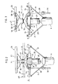
- the collection head 22 also comprises a suspension ensuring, at the bow 23 relative to the end of the fork arms 21, an elastic clearance in a direction YY (FIGS. 2 to 4) perpendicular to the plane of the base 1, c ' that is to say in service perpendicular to the ground.
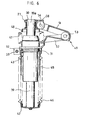
- the aforementioned suspension comprises a slide formed by two telescopic elements constituting the rod 39 and the body 29 of a single central plunger 28 interposed between the fork legs 21 and the middle of the bow 23, c ' that is to say, in the example shown, the middle of the cross member 27.
- the body 29 of the plunger 28 is fixed to a shoe 31 by means of a fixing system comprising two flanges 32 and a tie rod 33.
- the shoe 31 rigidly carries two opposite pins 34 directed in a axis XX parallel to axis 8, and mounted for rotation by means of ball bearings, in the ends of the fork arms 21.
- An anti-sway rod 36 articulated between the end of a lug 37 secured to the lower arm 4 and directed towards the base 1, and the end of a lever 38 also directed towards the base 1 and rigidly fixed to the shoe 31, ensures that the axis YY of the plunger 28 remains substantially perpendicular to the plane of the base 1 whatever the inclination of the upper arm 6.
- the plunger 28 further comprises a rod 39 mounted to slide in the body 29, and fitted and welded by its upper end 39a in a bore 30 of the cross member 27.
- two ball circulation slides 41 are interposed between the body 29 and the rod 39 to facilitate the translation of the latter.
- the rod 39 passes axially through the body 29.
- a cup 42 fixed to the end of the rod 39 opposite the crosspiece 27 covers the lower part of the body 29.
- a tension spring 43 whose turns are screwed, at one of its ends , on a threaded sleeve 44 fixed around the body 29, and, at its other end, in the internal threaded wall of the cup 42, constantly tends to bring the cup 42 against the base of the body 29, that is to say tell to move the crosspiece 27 away from the body 29.
- the collecting head comprises guide means for immobilizing the bow 23 in rotation relative to the folding structure 3 around the axis YY of the plunger 28, this axis YY being substantially perpendicular to the ground thanks to the link 36.
- These guide means comprise a compass 49 formed of two triangles 51, 52, articulated to one another by one of their vertices by means of a ball joint.
- the upper triangle 51 has for this purpose a yoke in which is fixed an axis 53 parallel to the axis 8 and which can pivot relative to the triangle 52 by means of an oscillating ball bearing 54.
- the two other vertices of the upper triangle 51 which constitute one of the ends of the compass 49, are articulated by means of axes 56 parallel to the axis 53, and of ball bearings 57, between yokes 58 welded to cross 27.
- the two other vertices of the lower triangle 52, which constitute the other end of the compass 49, are articulated in the same way, by means of axes 59 parallel to the axis 53, and ball bearings, between clevis 61 fixed on shoe 31.
- the stroke of the rod 39 relative to the body 29 of the plungers 28 can be at least about 50 mm, and the stiffness of the tension spring 43, less than 2500 N / m.
- the stroke of the rod 39 of the plunger is 150 mm, the diameter of this rod is 40 mm, and the stiffness of the elastic means of the plunger is 1200 N / m.
- the weight associated with the mobile mass of the folding structure is balanced, and when the bow 23 is in contact with a catenary, the static force with which it is applied against the catenary is substantially constant whatever the extension of the structure 3.
- the anti-sway rod 36 keeps the bow 23 substantially parallel to the plane that the base 1 when the cross member 27 is not subjected to any torsion.
- the catenary during movement, tilts to approach or move away from the ground, the corresponding inclinations of the bow 23 are ensured by the torsional flexibility of the cross-member 27 or any other suitable system.
- the position thus obtained is intermediate between the position of maximum extension of the rod 39 outside the body 29 shown in FIG. 4, and the position of maximum contraction of the rod 39 inside the body 29 represented in FIG. 6.
- the end of the tiege 39 opposite the crosspiece 27 projects out of the body 29, towards the '' base 1.
- the diver 28 absorbs most of the irregularities or oscillations of low and medium amplitude, while the folding structure 3 essentially has the role of giving the body 29 of the diver 28 an average altitude allowing it to absorb these irregularities in extension as in contraction of the spring 43.
- the compass 49 prevents the entry into rotation of the bow 23 around the axis YY under the effect of the torque exerted by the friction of the catenary on the bars 24 in the aforementioned case where the point of contact with the catenary is offset laterally.
- the capture head 22 comprising a single plunger, it is not necessary for the construction to rigorously position the axis of this plunger relative to other elements of the capture head such as the axis of another plunger , despite the fact that the bow 23 is fixed instead of being articulated to the rod 39 of the plunger 29.
- the capture head according to the invention is not very sensitive to aerodynamic effects, and thanks to the low surface area. because of its frontal profile, it makes it possible to further reduce the influence of these effects. Combined with the folding structure which has been described above and which itself has a small front profile, the collecting head is even more advantageous in this respect.
- the invention makes it possible to produce a pantograph provided for very high speeds (300 km / h for example with regard to current trains), in a surprisingly simple and economical manner in comparison with the pantographs described in the prior art for these applications.
- the capture head can be adapted to other embodiments of the folding structure, for example such as structures of the rhombus type, or even be adapted to the poles of vehicles such as trolleybuses or trams.
- the pick-up head can also be advantageous for slower vehicles, especially if the catenaries have significant variations in flexibility.
- the mounting of the plunger at the top of the mobile structure can be modified provided that the essential kinematic properties of the invention are preserved.
- the guide means for immobilizing the bow in rotation about the axis of the plunger can be modified.
- these means can reside in a particular section of the rod 39, this rod 39 sliding in a slide of corresponding section arranged in the body such as 29.
- These means can also be constituted by a second plunger mounted parallel to the first between the shoe such as 31 and cross member such as 27, so that the axes of the two plungers are carried by a common plane perpendicular to the tubular axis 8.
- the stiffness of the elastic means of the collecting head is of course the sum of the stiffness of the two divers.
- pantograph various devices can be added to the pantograph, such as for example a pneumatic device or the like for folding up the structure 3 against the effect of the springs 12.
Landscapes
- Engineering & Computer Science (AREA)
- Power Engineering (AREA)
- Transportation (AREA)
- Mechanical Engineering (AREA)
- Current-Collector Devices For Electrically Propelled Vehicles (AREA)
Claims (13)
Priority Applications (1)
| Application Number | Priority Date | Filing Date | Title |
|---|---|---|---|
| AT82400363T ATE15013T1 (de) | 1981-03-04 | 1982-03-03 | Abnehmerkopf fuer scherenstromabnehmer. |
Applications Claiming Priority (2)
| Application Number | Priority Date | Filing Date | Title |
|---|---|---|---|
| FR8104290 | 1981-03-04 | ||
| FR8104290A FR2501128A1 (fr) | 1981-03-04 | 1981-03-04 | Tete de captage pour pantographe et pantographe ainsi equipe |
Publications (2)
| Publication Number | Publication Date |
|---|---|
| EP0060189A1 EP0060189A1 (de) | 1982-09-15 |
| EP0060189B1 true EP0060189B1 (de) | 1985-08-21 |
Family
ID=9255847
Family Applications (1)
| Application Number | Title | Priority Date | Filing Date |
|---|---|---|---|
| EP82400363A Expired EP0060189B1 (de) | 1981-03-04 | 1982-03-03 | Abnehmerkopf für Scherenstromabnehmer |
Country Status (4)
| Country | Link |
|---|---|
| EP (1) | EP0060189B1 (de) |
| AT (1) | ATE15013T1 (de) |
| DE (2) | DE60189T1 (de) |
| FR (1) | FR2501128A1 (de) |
Families Citing this family (11)
| Publication number | Priority date | Publication date | Assignee | Title |
|---|---|---|---|---|
| DE19529065C1 (de) * | 1995-08-08 | 1997-02-27 | Abb Patent Gmbh | Stromabnehmer |
| GB2405391A (en) * | 2003-09-01 | 2005-03-02 | Bombardier Transp | Electric current collector for transmitting electrical energy between an electrical line and a vehicle |
| CN101275874B (zh) * | 2004-08-12 | 2011-05-18 | 中南大学 | 高精度微型传感器的力引导装置 |
| CN101531141B (zh) * | 2009-04-24 | 2011-01-26 | 田耕 | 电动汽车与充电站之间的充电接触装置 |
| CN103129401B (zh) * | 2011-11-26 | 2015-07-22 | 南车青岛四方机车车辆股份有限公司 | 车顶受电系统的车体连接阻尼装置及其方法 |
| FR3017829B1 (fr) | 2014-02-24 | 2016-02-12 | Faiveley Transp Tours | Pantographe de vehicule ferroviaire |
| CN107685634B (zh) * | 2017-08-30 | 2020-05-08 | 北京中车赛德铁道电气科技有限公司 | 一种气囊式受电弓底架焊接结构 |
| CN108128169B (zh) * | 2017-12-27 | 2024-03-22 | 青岛特来电新能源科技有限公司 | 车载受电弓及车载受电弓防护装置 |
| CN111251895B (zh) * | 2020-01-21 | 2023-07-07 | 中车株洲电力机车有限公司 | 一种单碳滑板受电弓的导流罩和弓头组件 |
| AT526558A1 (de) * | 2022-09-30 | 2024-04-15 | Siemens Mobility Austria Gmbh | Trägeranordnung für einen Stromabnehmer, Kit, Stromabnehmer und Schienenfahrzeug |
| CN117565683B (zh) * | 2024-01-16 | 2024-04-30 | 北京京仪敬业电工科技有限公司 | 基于城市地铁电力牵引系统的刚性接触网同相供电装置 |
Family Cites Families (4)
| Publication number | Priority date | Publication date | Assignee | Title |
|---|---|---|---|---|
| GB404396A (en) * | 1932-08-31 | 1934-01-18 | Frank Whyman | Improvements in current collecting devices for electric railway vehicles |
| FR2136975B2 (de) * | 1971-05-10 | 1973-05-11 | Faiveley Sa | |
| GB1506855A (en) * | 1975-11-14 | 1978-04-12 | Brecknell Willis & Co Ltd | Electric current collecting pantograph |
| AT358627B (de) * | 1978-03-14 | 1980-09-25 | Wilhelm Buchberger | Halbscheren-stromabnehmer |
-
1981
- 1981-03-04 FR FR8104290A patent/FR2501128A1/fr active Granted
-
1982
- 1982-03-03 DE DE198282400363T patent/DE60189T1/de active Pending
- 1982-03-03 DE DE8282400363T patent/DE3265521D1/de not_active Expired
- 1982-03-03 EP EP82400363A patent/EP0060189B1/de not_active Expired
- 1982-03-03 AT AT82400363T patent/ATE15013T1/de not_active IP Right Cessation
Also Published As
| Publication number | Publication date |
|---|---|
| DE3265521D1 (en) | 1985-09-26 |
| FR2501128B1 (de) | 1984-01-20 |
| ATE15013T1 (de) | 1985-09-15 |
| FR2501128A1 (fr) | 1982-09-10 |
| EP0060189A1 (de) | 1982-09-15 |
| DE60189T1 (de) | 1983-01-20 |
Similar Documents
| Publication | Publication Date | Title |
|---|---|---|
| EP0458665B1 (de) | Hinterradaufhängung eines Kraftfahrzeugs | |
| EP0238768B1 (de) | Lager- und Aufhängungsvorrichtung, verbunden mit dem Vorderrad eines Motorfahrrades | |
| EP0060189B1 (de) | Abnehmerkopf für Scherenstromabnehmer | |
| FR2628377A1 (fr) | Dispositif de liaison entre une roue directrice et un organe de commande de direction | |
| FR2536345A1 (fr) | Suspension a triangles superposes et angle de chasse variable pour vehicules | |
| FR2730457A1 (fr) | Dispositif de suspension de vehicule a roue avant directrice et vehicule correspondant | |
| FR2759340A1 (fr) | Systeme de guidage le long d'au moins un rail au sol pour un essieu d'un vehicule routier | |
| FR2588217A1 (fr) | Suspension de roue arriere independante | |
| EP0279135B1 (de) | Aufhängungs- und Schwenkvorrichtung von einem lenkbaren Rad eines Kraftfahrzeuges | |
| FR2699866A1 (fr) | Ensemble anti-roulis pour véhicule. | |
| EP3222485B1 (de) | Schienenfahrzeugdrehgestell, das eine versetzte primäre federungsvorrichtung umfasst | |
| FR2698825A1 (fr) | Dispositif de liaison entre les roues et le châssis d'un véhicule. | |
| CA2736696C (fr) | Bogie moteur | |
| FR3071813A1 (fr) | Vehicule automobile routier attelable a suspension et direction compacte | |
| EP0444973B1 (de) | Scherenstromabnehmer mit zwei konjugierten Köpfen eines schienengebundenen Triebfahrzeuges | |
| EP0588694B1 (de) | Hinterradaufhängung für Kraftfahrzeug mit unabhängigen Rädern | |
| EP0223640B1 (de) | Anhängbares Fahrzeug mit einer verlängerbaren Kupplung | |
| EP1792758A1 (de) | Weicher Anschlag für die Aufhängung eines Fahrzeugs | |
| EP0538116A1 (de) | Aufhängung, insbesondere mit gezogenen Lenkern für Kraftfahrzeug, mit einem Dämpfungssystem für längsgerichtete Stösse | |
| FR2809069A1 (fr) | Vehicule ferroviaire comportant une voiture d'extremite se prolongeant par une cabine | |
| EP1170156B1 (de) | Hinterradaufhängung mit Schwingarm für ein Kraftfahrzeug mit Querführungsstreben | |
| FR2607449A1 (fr) | Dispositif de suspension pour train de roues independantes de vehicule | |
| EP0962341B1 (de) | Radaufhängung für eine landwirtschaftliche Maschine, z.B. eine Feldspritze | |
| FR2674187A1 (fr) | Dispositif formant suspension notamment de roue arriere d'un vehicule automobile. | |
| EP0914977A1 (de) | Hinterachse mit einer Gelenkvorrichtung zwischen einem oszillierenden Längslenker und dem Kraftfahrzeugaufbau |
Legal Events
| Date | Code | Title | Description |
|---|---|---|---|
| PUAI | Public reference made under article 153(3) epc to a published international application that has entered the european phase |
Free format text: ORIGINAL CODE: 0009012 |
|
| 17P | Request for examination filed |
Effective date: 19820306 |
|
| AK | Designated contracting states |
Designated state(s): AT BE CH DE GB IT NL SE |
|
| ITCL | It: translation for ep claims filed |
Representative=s name: BARZANO' ZANARDO |
|
| TCAT | At: translation of patent claims filed | ||
| TCNL | Nl: translation of patent claims filed | ||
| DET | De: translation of patent claims | ||
| ITF | It: translation for a ep patent filed |
Owner name: BARZANO' E ZANARDO ROMA S.P.A. |
|
| GRAA | (expected) grant |
Free format text: ORIGINAL CODE: 0009210 |
|
| AK | Designated contracting states |
Designated state(s): AT BE CH DE GB IT LI NL SE |
|
| REF | Corresponds to: |
Ref document number: 15013 Country of ref document: AT Date of ref document: 19850915 Kind code of ref document: T |
|
| PG25 | Lapsed in a contracting state [announced via postgrant information from national office to epo] |
Ref country code: SE Effective date: 19850830 |
|
| REF | Corresponds to: |
Ref document number: 3265521 Country of ref document: DE Date of ref document: 19850926 |
|
| PG25 | Lapsed in a contracting state [announced via postgrant information from national office to epo] |
Ref country code: AT Effective date: 19860303 |
|
| PG25 | Lapsed in a contracting state [announced via postgrant information from national office to epo] |
Ref country code: LI Effective date: 19860331 Ref country code: CH Effective date: 19860331 Ref country code: BE Effective date: 19860331 |
|
| PLBE | No opposition filed within time limit |
Free format text: ORIGINAL CODE: 0009261 |
|
| STAA | Information on the status of an ep patent application or granted ep patent |
Free format text: STATUS: NO OPPOSITION FILED WITHIN TIME LIMIT |
|
| 26N | No opposition filed | ||
| BERE | Be: lapsed |
Owner name: FAIVELEY ENTREPRISES Effective date: 19860331 |
|
| REG | Reference to a national code |
Ref country code: CH Ref legal event code: PL |
|
| ITTA | It: last paid annual fee | ||
| ITPR | It: changes in ownership of a european patent |
Owner name: CESSIONE;FAIVELEY TRANSPORT |
|
| REG | Reference to a national code |
Ref country code: GB Ref legal event code: 732E |
|
| NLS | Nl: assignments of ep-patents |
Owner name: FAIVELEY TRANSPORT |
|
| PGFP | Annual fee paid to national office [announced via postgrant information from national office to epo] |
Ref country code: GB Payment date: 19980303 Year of fee payment: 17 |
|
| PGFP | Annual fee paid to national office [announced via postgrant information from national office to epo] |
Ref country code: NL Payment date: 19980331 Year of fee payment: 17 |
|
| PGFP | Annual fee paid to national office [announced via postgrant information from national office to epo] |
Ref country code: DE Payment date: 19980526 Year of fee payment: 17 |
|
| PG25 | Lapsed in a contracting state [announced via postgrant information from national office to epo] |
Ref country code: GB Free format text: LAPSE BECAUSE OF NON-PAYMENT OF DUE FEES Effective date: 19990303 |
|
| PG25 | Lapsed in a contracting state [announced via postgrant information from national office to epo] |
Ref country code: NL Free format text: LAPSE BECAUSE OF NON-PAYMENT OF DUE FEES Effective date: 19991001 |
|
| GBPC | Gb: european patent ceased through non-payment of renewal fee |
Effective date: 19990303 |
|
| NLV4 | Nl: lapsed or anulled due to non-payment of the annual fee |
Effective date: 19991001 |
|
| PG25 | Lapsed in a contracting state [announced via postgrant information from national office to epo] |
Ref country code: DE Free format text: LAPSE BECAUSE OF NON-PAYMENT OF DUE FEES Effective date: 20000101 |