EP1217743A2 - Berührungslose Schalteinrichtung - Google Patents
Berührungslose Schalteinrichtung Download PDFInfo
- Publication number
- EP1217743A2 EP1217743A2 EP01123124A EP01123124A EP1217743A2 EP 1217743 A2 EP1217743 A2 EP 1217743A2 EP 01123124 A EP01123124 A EP 01123124A EP 01123124 A EP01123124 A EP 01123124A EP 1217743 A2 EP1217743 A2 EP 1217743A2
- Authority
- EP
- European Patent Office
- Prior art keywords
- resistor
- resistors
- actuator
- switching
- switching device
- Prior art date
- Legal status (The legal status is an assumption and is not a legal conclusion. Google has not performed a legal analysis and makes no representation as to the accuracy of the status listed.)
- Withdrawn
Links
Images


Classifications
-
- H—ELECTRICITY
- H03—ELECTRONIC CIRCUITRY
- H03K—PULSE TECHNIQUE
- H03K17/00—Electronic switching or gating, i.e. not by contact-making and –breaking
- H03K17/94—Electronic switching or gating, i.e. not by contact-making and –breaking characterised by the way in which the control signals are generated
- H03K17/945—Proximity switches
- H03K17/95—Proximity switches using a magnetic detector
- H03K17/9517—Proximity switches using a magnetic detector using galvanomagnetic devices
-
- H—ELECTRICITY
- H03—ELECTRONIC CIRCUITRY
- H03K—PULSE TECHNIQUE
- H03K17/00—Electronic switching or gating, i.e. not by contact-making and –breaking
- H03K17/94—Electronic switching or gating, i.e. not by contact-making and –breaking characterised by the way in which the control signals are generated
- H03K17/945—Proximity switches
- H03K17/95—Proximity switches using a magnetic detector
- H03K17/952—Proximity switches using a magnetic detector using inductive coils
- H03K17/9525—Proximity switches using a magnetic detector using inductive coils controlled by an oscillatory signal
-
- H—ELECTRICITY
- H03—ELECTRONIC CIRCUITRY
- H03K—PULSE TECHNIQUE
- H03K17/00—Electronic switching or gating, i.e. not by contact-making and –breaking
- H03K17/94—Electronic switching or gating, i.e. not by contact-making and –breaking characterised by the way in which the control signals are generated
- H03K17/945—Proximity switches
- H03K17/955—Proximity switches using a capacitive detector
-
- H—ELECTRICITY
- H03—ELECTRONIC CIRCUITRY
- H03K—PULSE TECHNIQUE
- H03K17/00—Electronic switching or gating, i.e. not by contact-making and –breaking
- H03K17/94—Electronic switching or gating, i.e. not by contact-making and –breaking characterised by the way in which the control signals are generated
- H03K17/965—Switches controlled by moving an element forming part of the switch
- H03K17/97—Switches controlled by moving an element forming part of the switch using a magnetic movable element
-
- H—ELECTRICITY
- H03—ELECTRONIC CIRCUITRY
- H03K—PULSE TECHNIQUE
- H03K17/00—Electronic switching or gating, i.e. not by contact-making and –breaking
- H03K17/94—Electronic switching or gating, i.e. not by contact-making and –breaking characterised by the way in which the control signals are generated
- H03K17/965—Switches controlled by moving an element forming part of the switch
- H03K17/97—Switches controlled by moving an element forming part of the switch using a magnetic movable element
- H03K2017/9706—Inductive element
-
- H—ELECTRICITY
- H03—ELECTRONIC CIRCUITRY
- H03K—PULSE TECHNIQUE
- H03K17/00—Electronic switching or gating, i.e. not by contact-making and –breaking
- H03K17/94—Electronic switching or gating, i.e. not by contact-making and –breaking characterised by the way in which the control signals are generated
- H03K17/965—Switches controlled by moving an element forming part of the switch
- H03K17/97—Switches controlled by moving an element forming part of the switch using a magnetic movable element
- H03K2017/9713—Multiposition, e.g. involving comparison with different thresholds
-
- H—ELECTRICITY
- H03—ELECTRONIC CIRCUITRY
- H03K—PULSE TECHNIQUE
- H03K2217/00—Indexing scheme related to electronic switching or gating, i.e. not by contact-making or -breaking covered by H03K17/00
- H03K2217/94—Indexing scheme related to electronic switching or gating, i.e. not by contact-making or -breaking covered by H03K17/00 characterised by the way in which the control signal is generated
- H03K2217/94057—Rotary switches
- H03K2217/94068—Rotary switches with magnetic detection
-
- H—ELECTRICITY
- H03—ELECTRONIC CIRCUITRY
- H03K—PULSE TECHNIQUE
- H03K2217/00—Indexing scheme related to electronic switching or gating, i.e. not by contact-making or -breaking covered by H03K17/00
- H03K2217/94—Indexing scheme related to electronic switching or gating, i.e. not by contact-making or -breaking covered by H03K17/00 characterised by the way in which the control signal is generated
- H03K2217/96—Touch switches
- H03K2217/9607—Capacitive touch switches
- H03K2217/960735—Capacitive touch switches characterised by circuit details
- H03K2217/960745—Capacitive differential; e.g. comparison with reference capacitance
Definitions
- the invention relates to a switching device for generation and evaluation of a switching signal.
- the invention relates also a method for generating and evaluating a Switching signal.
- switching devices have for example mechanical sliding contacts. Sliding contacts are here over contact areas PCB moves. Depending on the position Actuating element of such a switching device the sliding contacts connect different contact points the circuit board with each other. By connecting the corresponding contact points with each other Switching signals given. Such switching signals can by evaluated for example a central control unit and a process assigned to the switching signal initiate.
- Such switching devices are for example in Motor vehicle construction known in many ways.
- the Switching devices can be used, for example, as toggle switches, Pushbutton switches, swivel switches, rotary switches or the like. be trained.
- the invention is therefore based on the object Switching device and a method of the input further described type, which no wear subject. Nevertheless, reliable production should be and evaluation of a switching signal can be guaranteed.
- This task is at the beginning of a switching device mentioned type according to the invention solved in that the Device at least one contactlessly influenceable, changing its resistance value due to the influence Resistor, one in the area surrounding the resistor movable and thus influencing the resistance and one downstream of the resistance, the Evaluation unit detecting resistance value, wherein by moving the actuator into the surrounding area of the The resistance changes its resistance value and the evaluation unit evaluates the change in resistance.
- Such a switching device has in particular the Advantage that due to the non-contact influence No wear between the actuator and the resistor corresponding resistance can take place. That by moving of the actuator in the range of the influenceable resistance generated switching signal is constant with the same quality generated. Wear of both the actuator and the influenceable resistance due to a frequent Generation of switching signals cannot, according to the invention occur.
- a particularly preferred embodiment of the invention is characterized in that at least two resistors are present that one of the resistors as Reference resistor and at least one other resistor formed as a resistor that can be influenced by the actuator is, the evaluation unit by comparing the Output signals of the reference resistor and the at least a switchable resistance a switching signal evaluates. Due to the reference resistance, a switching signal differentiating the reference resistance the evaluation unit can be evaluated. You can especially due to the influence of the corresponding Changes in resistance value in a simple way and Be recorded and evaluated in this way.
- the at least one influenceable resistor with AC applied frequency dependent resistor is.
- a frequency-dependent resistor is suitable especially to be influenced by an actuator and change its resistance value.
- a particularly preferred embodiment according to the invention is characterized in that a Oscillator, a first one downstream of the oscillator frequency-dependent resistance (reference resistance) and a downstream of the oscillator, to the first resistor parallel inverter is provided, the Inverter a second frequency dependent resistor (influenceable resistance) is connected downstream that first resistor and the second resistor an adder, which adds the output signals of the two resistors and an evaluation logic that due to a changing Output signal of the adder due to the contactless Influencing one of the two resistors by the actuator, evaluates a switching signal, is connected downstream.
- a Such switching device has the advantage that functionally reliable way generates a switching signal and can be evaluated.
- the frequency-dependent resistor is a capacitive resistor and the actuator is an insulator with a particularly high permittivity number.
- a permittivity number of ⁇ r approx. 3 has proven to be favorable.
- Embodiment of the invention have a resistors identical resistance characteristics. This has the Advantage that with unaffected resistance the Output signal of the adder is zero. The two Output signals of the resistors rise due to the an inverted signal completely. at Influencing at least one resistance is that Output signal of the adder not equal to zero, since then the output signals of the individual resistors are not cancel completely. This can be a very simple and nevertheless very precise determination of the switching signal.
- the switch unit has an actuating element.
- the actuating element can be directly or indirectly coupled to the actuator.
- the switch unit can advantageously have a printed circuit board.
- the Switch unit is designed as a vehicle switch.
- Vehicle switches in particular, are subject to frequent actuation of wear.
- An inventive Switch unit has the advantage that it is wear-free is working.
- the switch unit can be used as a steering angle sensor be formed, the actuator on a turntable of the Steering angle sensor of a vehicle is arranged and each after rotation of the disc in the range of influenceable Resistance arrives on the orbit of the Disc are arranged. Depending on the rotation or rotational position of the disc are different resistances from the actuator influenced in succession or at the same time. This Influencing can be detected and a switching signal be evaluated. About such a switch unit the rotation position of the turntable can be clearly and be recorded without contact.
- the switch unit is designed as a steering column switch and that Actuator a shift lever of the steering column switch is.
- Steering column switches in particular are very subject frequent activity. Switch units with known Sliding contacts tend to wear. On Steering column switch according to the invention is subject advantageously no wear.
- a switching signal can be generated using such a method generated without contact. Wear can thus do not occur.
- a particularly advantageous development of the method is characterized in that at least two resistors are present that one of the resistors as Reference resistor and at least one other resistor formed as a resistor that can be influenced by the actuator is, the evaluation unit by comparing the Output signals of the reference resistor and the at least a switchable resistance a switching signal evaluates. By comparing the two resistors be guaranteed that a switching signal is detected.
- an oscillator can also advantageously be used be provided, the two connected in parallel influenceable, frequency-dependent resistors with one Oscillator signal applied, wherein between the Oscillator and one of the two resistors that Oscillator signal is inverted, and wherein the Output signals of the resistors are added and that added output signal is evaluated.
- the resistances are identical Resistance characteristics, where unaffected resistors the added output signal zero and when influenced by at least one resistor is not zero. This is a clear record and evaluation of a switching signal possible.
- the circuit diagram shown in Figure 1 is a special one preferred embodiment of the invention has a Oscillator 1 on.
- the oscillator 1 is a first frequency-dependent resistor 3 as a reference resistor downstream.
- the oscillator 1 is on Inverter 5 connected downstream of the oscillator 1 outgoing signal inverted by 180 °.
- the inverter 5 is again a second frequency-dependent resistor 7 as influenceable resistor connected downstream.
- the Output signals of the two resistors 3 and 7 are from an adder 9 added.
- the output signal of the adder 9 is fed to an evaluation logic 11.
- Figure 1 shows furthermore a movable actuator 13 running along the line 15 can be moved.
- resistor 3 is advantageously identical to that Resistor 7.
- Resistors 3 and 7 are advantageously frequency-dependent, inductive Resistances.
- the actuator 13 is advantageously as ferromagnetic metal formed.
- the Actuator 13 In the switching position shown in Figure 1, the Actuator 13 the distance a to the resistor 7. The actuator 13 is not yet in the area surrounding the frequency-dependent resistor 7 occurred, i.e. the Actuator 13 does not yet affect resistor 7.
- the actuator 13 is dashed into that in FIG. 1 Position 13 'shown, the distance is between the actuator 13 and the resistor 7 the value b. This distance is within the surrounding area of the Resistor 7, within which the resistance 7 of the Actuator is influenced.
- resistor 7 If resistor 7 is not affected, the output signal is of the adder 9 zero, since there are identical resistors 3 and 7 the output signals of resistors 3 and 7 due to the inverted input signal of the resistor 7 cancel.
- the evaluation logic 11 can accordingly in a simple manner and differentiate between two switch positions, namely between the in which the output signal of the Adder is zero and that at which the output signal of the adder 9 is not equal to zero.
- Switching device has no wear subject.
- the influenceable resistor 7 is from the Actuator 13 influences the actuator 13 without the resistance 7 touches.
- Figures 2 and 3 show two different ones Switch positions of a steering column switch with a switch unit according to the invention.
- Figure 2 shows a Shift lever 17, which is arranged pivotably about an axis 19 is.
- the shift lever 17 has at its in Figures 2 and 3 shown free end an actuator 13.
- Figures 2 and 3 also show for example, one control electronics 21 and one Evaluation electronics 23.
- the shift lever 17 is, for example, via a Actuating element 25 that can be actuated on the actuator 13 opposite side of the shift lever 17 is arranged.
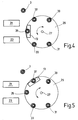
- FIGS Figures 4 and 5 Another embodiment of the invention is shown in FIGS Figures 4 and 5 shown.
- the actuator 13 is open a turntable 29 rotatable about an axis 27.
- the turntable 29 is part of a Steering angle sensor for a vehicle. With such a Steering angle sensor is the axis of rotation 27 with the steering column a vehicle steering coupled in a rotationally fixed manner.
- Above the Turntable 29 are on the orbit of the turntable 29 different resistances that can be influenced 31, 33, 35, 37 and 39 arranged.
- FIG. 4 shows the resistor 35 from the actuator 13 affected.
- Resistor 37 is slightly twisted by the actuator 13 influenced.
- Particular advantage of the embodiment according to FIGS. 4 and 5 is that the position of the turntable 29 or that coupled steering angle of a vehicle without contact can be determined.
- a corresponding switching signal is from the contactlessly influenceable resistor 31 - 39 generated and evaluated by the evaluation electronics 23.
Landscapes
- Transmission And Conversion Of Sensor Element Output (AREA)
- Measurement Of Length, Angles, Or The Like Using Electric Or Magnetic Means (AREA)
- Testing Electric Properties And Detecting Electric Faults (AREA)
- Keying Circuit Devices (AREA)
Abstract
Description
Zur ortsfesten Anordnung der Widerstände kann die Schaltereinheit vorteilhafterweise eine Leiterplatte aufweisen.
- Bewegen eines Aktors in den Umgebungsbereich eines berührungslos beeinflussbaren Widerstandes, wobei der Widerstand aufgrund der Beeinflussung seinen Widerstandswert ändert und ein Schaltsignal erzeugt, und
- Erfassung der Widerstandsänderung und Auswertung des Schaltsignals.
- Figur 1
- das Schaltschema einer erfindungsgemäßen Schalteinrichtung,
- Figur 2 und 3
- eine erfindungsgemäße Schalteinrichtung in Form eines Lenkstockschalters und
- Figur 4 und 5
- eine erfindungsgemäße Schalteinrichtung in Form eines Lenkwinkelsensors.
Claims (17)
- Schalteinrichtung zur Erzeugung und Auswertung eines Schaltsignals, dadurch gekennzeichnet, dass die Einrichtung wenigstens einen berührungslos beeinflussbaren, aufgrund der Beeinflussung seinen Widerstandswert ändernden Widerstand (7, 31 - 39), einen in den Umgebungsbereich des Widerstandes (7, 31 - 39) bewegbaren und damit den Widerstand (7, 31 - 39) beeinflussenden Aktor (13) sowie eine dem Widerstand (7, 31 - 39) nachgeschaltete, den Widerstandswert erfassende Auswerteeinheit (9, 11, 23) aufweist, wobei durch Bewegen des Aktors (13) in den Umgebungsbereich des Widerstandes (7, 31 - 39) der Widerstand (7, 31 - 39) seinen Widerstandswert ändert und die Auswerteeinheit (9, 11, 23) die Widerstandswertänderung auswertet.
- Schalteinrichtung nach Anspruch 1, dadurch gekennzeichnet, dass wenigstens zwei Widerstände (3, 7, 31 - 39) vorhanden sind, dass einer der Widerstände (3) als Referenzwiderstand und wenigstens ein weiterer Widerstand (7, 31 - 39) als von dem Aktor (13) beeinflussbarer Widerstand (7, 31 - 39) ausgebildet ist, wobei die Auswerteeinheit (9, 11, 23) durch Vergleich der Ausgangssignale des Referenzwiderstandes (3) und des wenigstens einen beeinflussbaren Widerstandes (7, 31 - 39) ein Schaltsignal auswertet.
- Schalteinrichtung nach Anspruch 1 oder 2, dadurch gekennzeichnet, dass der wenigstens eine beeinflussbare Widerstand ein mit Wechselstrom beaufschlagter frequenzabhängiger Widerstand (7, 31 - 39) ist.
- Schalteinrichtung nach Anspruch 3, dadurch gekennzeichnet, dass ein Oszillator (1), ein dem Oszillator (1) nachgeschalteter erster frequenzabhängiger Widerstand (Referenzwiderstand 3) und ein dem Oszillator (1) nachgeschalteter, zu dem ersten Widerstand (3) parallel angeordneter Inverter (5) vorgesehen ist, wobei dem Inverter (5) ein zweiter frequenzabhängiger Widerstand (beeinflussbarer Widerstand 7) nachgeschaltet ist, dass dem ersten Widerstand (3) und dem zweiten Widerstand (7) ein Addierer (9), der die Ausgangssignale der beiden Widerstände (3, 7) addiert, und eine Auswertelogik (11), die aufgrund eines sich ändernden Ausgangssignals des Addierers (9) aufgrund der kontaktlosen Beeinflussung eines der beiden Widerstände (3, 7) durch den Aktor (13) ein Schaltsignal auswertet, nachgeschaltet ist.
- Schalteinrichtung nach Anspruch 4, dadurch gekennzeichnet, dass der wenigstens eine frequenzabhängige Widerstand (7, 31 - 39) ein induktiver Widerstand ist und dass der Aktor (13) ein ferromagnetisches Metall ist.
- Schalteinrichtung nach Anspruch 4, dadurch gekennzeichnet, dass der wenigstens eine frequenzabhängige Widerstand (7, 31 - 39) ein kapazitiver Widerstand ist und dass der Aktor (13) ein Isolator mit insbesondere einer hohen Permittivitätszahl (∈r ca. 3 oder höher) ist.
- Schalteinrichtung nach Anspruch 4, 5 oder 6, dadurch gekennzeichnet, dass die Widerstände (3, 7, 31 - 39) eine identische Widerstandswertcharakteristik aufweisen, wobei bei unbeeinflusstem Widerstand (3, 31 - 39) das Ausgangssignal des Addierers (9) null und bei Beeinflussung von wenigstens einem Widerstand (7, 31 - 39) ungleich null ist.
- Schalteinrichtung nach einem der vorhergehenden Ansprüche, dadurch gekennzeichnet, dass mehrere unterschiedliche, verschiedenen Schaltsignalen zuordenbare Aktoren vorhanden sind, welche den Widerstandswert des beeinflussbaren Widerstands unterschiedlich ändern, wobei die Auswerteeinheit aufgrund der jeweiligen Widerstandsänderung feststellt durch welchen Aktor die Widerstandsänderung erfolgte und die unterschiedlichen Schaltsignale auswertet.
- Schaltereinheit nach einem der vorhergehenden Ansprüche, dadurch gekennzeichnet, dass die Schaltereinheit ein Betätigungselement (25, 29) aufweist, das mittel- oder unmittelbar den Aktor (13) bewegt.
- Schaltereinheit nach einem der vorhergehenden Ansprüche, dadurch gekennzeichnet, dass die Schaltereinheit eine die Widerstände (3, 7, 31 - 39) tragende Leiterplatine aufweist.
- Schaltereinheit nach einem der vorhergehenden Ansprüche, dadurch gekennzeichnet, dass die Schaltereinheit als Fahrzeugschalter ausgebildet ist.
- Schaltereinheit nach Anspruch 11, dadurch gekennzeichnet, dass der Aktor auf einer Drehscheibe (29) eines Lenkwinkelsensors eines Fahrzeuges angeordnet ist und in den Bereich von beeinflussbaren Widerständen (31 - 39) gelangt, die auf der Umdrehungsbahn der Scheibe (29) angeordnet sind.
- Schaltereinheit nach Anspruch 11, dadurch gekennzeichnet, dass die Schaltereinheit als Lenkstockschalter ausgebildet ist und dass das Betätigungselement (25) ein Schalthebel (17) des Lenkstockschalters ist.
- Verfahren zur Erzeugung und Auswertung eines Schaltsignals, gekennzeichnet durch folgende Verfahrensschritte:Bewegen eines Aktors (13) in den Umgebungsbereich eines berührungslos beeinflussbaren Widerstandes (7, 31- 39), wobei der Widerstand (7, 31 - 39) aufgrund der Beeinflussung seinen Widerstandswert ändert und ein Schaltsignal erzeugt, undErfassung der Widerstandswertänderung und Auswertung des Schaltsignals.
- Verfahren nach Anspruch 14, dadurch gekennzeichnet, dass wenigstens zwei Widerstände (3, 7, 31 - 39) vorhanden sind, dass einer der Widerstände als Referenzwiderstand (3) und wenigstens ein weiterer Widerstand (7, 31 - 39) als von dem Aktor (13) beeinflussbarer Widerstand (7, 31 - 39) ausgebildet ist, wobei die Auswerteeinheit (9, 11, 23) durch Vergleich der Ausgangssignale des Referenzwiderstandes (3) und des wenigstens einen beeinflussbaren Widerstandes (7, 31 - 39) ein Schaltsignal auswertet.
- Verfahren nach Anspruch 14 oder 15, dadurch gekennzeichnet, dass ein Oszillator (1) zwei parallel geschaltete beeinflussbare, frequenzabhängige Widerstände (3, 7, 31 - 39) mit einem Oszillatorsignal beaufschlagt, wobei zwischen dem Oszillator (1) und einem der beiden Widerstände (3, 7, 31 - 39) das Oszillatorsignal invertiert wird, und wobei die Ausgangssignale der Widerstände (3, 7) addiert werden und das addierte Ausgangssignal ausgewertet wird.
- Schalteinrichtung nach Anspruch 14, 15 oder 16, dadurch gekennzeichnet, dass die Widerstände (3, 7, 31 - 39) eine identische Widerstandswertcharakteristik aufweisen, wobei bei unbeeinflussten Widerständen (3, 7, 31 - 39) das addierte Ausgangssignal null und bei Beeinflussung von wenigstens einem Widerstand (7, 31 - 39) ungleich null ist.
Applications Claiming Priority (2)
| Application Number | Priority Date | Filing Date | Title |
|---|---|---|---|
| DE2000164510 DE10064510A1 (de) | 2000-12-22 | 2000-12-22 | Schalteinrichtung |
| DE10064510 | 2000-12-22 |
Publications (2)
| Publication Number | Publication Date |
|---|---|
| EP1217743A2 true EP1217743A2 (de) | 2002-06-26 |
| EP1217743A3 EP1217743A3 (de) | 2006-02-01 |
Family
ID=7668620
Family Applications (1)
| Application Number | Title | Priority Date | Filing Date |
|---|---|---|---|
| EP01123124A Withdrawn EP1217743A3 (de) | 2000-12-22 | 2001-09-27 | Berührungslose Schalteinrichtung |
Country Status (2)
| Country | Link |
|---|---|
| EP (1) | EP1217743A3 (de) |
| DE (1) | DE10064510A1 (de) |
Cited By (3)
| Publication number | Priority date | Publication date | Assignee | Title |
|---|---|---|---|---|
| WO2006036950A1 (en) * | 2004-09-24 | 2006-04-06 | Touchsensor Technologies, Llc | Contactless multiposition switches using capacitive touch sensors |
| US7906875B2 (en) | 1999-01-19 | 2011-03-15 | Touchsensor Technologies, Llc | Touch switches and practical applications therefor |
| CN109802670A (zh) * | 2012-01-12 | 2019-05-24 | 沃拉克有限公司 | 用于响应于机械力生成电信号的方法和开关装置 |
Family Cites Families (15)
| Publication number | Priority date | Publication date | Assignee | Title |
|---|---|---|---|---|
| JP2550621B2 (ja) * | 1987-11-17 | 1996-11-06 | オムロン株式会社 | 高周波発振型近接スイッチ |
| DE4328427C2 (de) * | 1993-08-24 | 2003-08-07 | Teves Gmbh Alfred | Schalter mit Hallbaustein |
| DE4335895C2 (de) * | 1993-10-21 | 1996-11-14 | Telefunken Microelectron | Schaltungsanordnung zur Auswertung der Schalterstellung eines Drückerschalters |
| EP0668486A3 (de) * | 1994-02-22 | 1997-07-30 | Heidenhain Gmbh Dr Johannes | Längen- oder Winkelmesseinrichtung. |
| EP0723166B1 (de) * | 1995-01-18 | 2000-03-08 | Carlo Gavazzi Services AG | Kapazitiver Sensor |
| DE19614457C2 (de) * | 1996-04-12 | 2001-08-16 | Opel Adam Ag | Elektronischer Näherungsschalter |
| DE19631550A1 (de) * | 1996-07-26 | 1998-01-29 | Siemens Ag | Verfahren zum Offenbaren sicherungstechnisch relevanter Defekte an Radsensoren für Bahnanlagen und Einrichtung zur Durchführung des Verfahrens |
| DE19652935B4 (de) * | 1996-12-19 | 2005-04-21 | Valeo Schalter Und Sensoren Gmbh | Mit einem Resolver versehene Meßeinrichtung zur Messung des Lenkwinkels eines Fahrzeugs |
| DE19756475A1 (de) * | 1996-12-20 | 1998-06-25 | Linde Ag | Bedienhebel und Verfahren zum Betreiben des Bedienhebels |
| DE19741367C1 (de) * | 1997-09-19 | 1999-02-25 | Siemens Ag | Elektrischer Schalter |
| DE19808665C1 (de) * | 1998-03-02 | 1999-08-19 | Siemens Ag | Schalter, insbesondere Lenkstockschalter für ein Kraftfahrzeug |
| DE19831978A1 (de) * | 1998-07-16 | 2000-02-03 | Micronas Intermetall Gmbh | Sensorschaltung |
| DE19922500B4 (de) * | 1999-05-15 | 2005-12-15 | Valeo Schalter Und Sensoren Gmbh | Modulare Schaltervorrichtung, insbesondere für Kraftahrzeuge |
| DE19953204A1 (de) * | 1999-11-05 | 2001-05-10 | Valeo Schalter & Sensoren Gmbh | Schaltmodul zum Schalten von Steuerstrombahnen, insbesondere in Fahrzeugen |
| DE19956630A1 (de) * | 1999-11-25 | 2001-05-31 | Merten Gmbh & Co Kg | Kapazitiver Tastschalter |
-
2000
- 2000-12-22 DE DE2000164510 patent/DE10064510A1/de not_active Withdrawn
-
2001
- 2001-09-27 EP EP01123124A patent/EP1217743A3/de not_active Withdrawn
Non-Patent Citations (1)
| Title |
|---|
| None |
Cited By (6)
| Publication number | Priority date | Publication date | Assignee | Title |
|---|---|---|---|---|
| US7906875B2 (en) | 1999-01-19 | 2011-03-15 | Touchsensor Technologies, Llc | Touch switches and practical applications therefor |
| US8227940B2 (en) | 1999-01-19 | 2012-07-24 | Touchsensor Technologies, Llc | Touch switches and practical applications therefor |
| US9306561B2 (en) | 1999-01-19 | 2016-04-05 | Touchsensor Technologies, Llc | Touch switches and practical applications therefor |
| WO2006036950A1 (en) * | 2004-09-24 | 2006-04-06 | Touchsensor Technologies, Llc | Contactless multiposition switches using capacitive touch sensors |
| CN109802670A (zh) * | 2012-01-12 | 2019-05-24 | 沃拉克有限公司 | 用于响应于机械力生成电信号的方法和开关装置 |
| CN109802670B (zh) * | 2012-01-12 | 2023-04-07 | 沃拉克有限公司 | 用于响应于机械力生成电信号的方法和开关装置 |
Also Published As
| Publication number | Publication date |
|---|---|
| EP1217743A3 (de) | 2006-02-01 |
| DE10064510A1 (de) | 2002-07-04 |
Similar Documents
| Publication | Publication Date | Title |
|---|---|---|
| DE69401470T2 (de) | Steuerknüppel | |
| WO2011116929A1 (de) | Eingabevorrichtung mit haptischer rückmeldung | |
| DE19736454A1 (de) | Kontaktloser Näherungsschalter | |
| EP1261131B1 (de) | Induktive Gangschalteinheit | |
| EP3439178B1 (de) | Türgriffanordnung für ein kraftfahrzeug mit kapazitivem und induktivem sensor | |
| DE4331909A1 (de) | Drehwinkelgeber | |
| EP2210018B1 (de) | Sensor für die schaltstellung einer schaltwelle und entsprechendes ermittlungsverfahren | |
| EP2647126B1 (de) | Bedieneinheit mit kapazitivem berührungssensor | |
| DE102008041806A1 (de) | Bedieneinrichtung | |
| DE102019135872B3 (de) | Bedienelement mit bauraumsparender Kombination aus Rasthaptik und elektromechanischer Stellungsdetektion | |
| DE102020132196B4 (de) | Vorrichtung umfassend ein bewegliches Objekt und eine Einrichtung zur Erfassung einer Bewegung des Objekts, Eingabegerät mit dieser Vorrichtung und Verfahren zum Betreiben dieser Vorrichtung | |
| DE10064510A1 (de) | Schalteinrichtung | |
| DE102004038872A1 (de) | Kapazitiver Berührungsschalter für eine Bedieneinrichtung eines Elektrogeräts, Bedieneinrichtung sowie Verfahren zur Auswertung | |
| DE19756475A1 (de) | Bedienhebel und Verfahren zum Betreiben des Bedienhebels | |
| DE202020106974U1 (de) | Vorrichtung zur Erfassung eines Tastendrucks, Tastatur | |
| DE19732890A1 (de) | Deichselkopf für ein deichselgelenktes Flurförderzeug | |
| EP0989677B1 (de) | Kodierer zur Umwandlung einer analogen Eingabe in Digitalsignale | |
| DE3109911C1 (de) | Kapazitiver Signalgeber | |
| EP2656364B1 (de) | Schaltvorrichtung mit schaltzustandserkennung | |
| WO1989004566A1 (fr) | Element de codage | |
| DE102015219348B3 (de) | Taster für eine kontaktvorrichtung | |
| DE3906917C2 (de) | ||
| DE3222059A1 (de) | Kraftfahrzeuglenkstockschalter | |
| DE102023130716A1 (de) | Bedienvorrichtung für ein Kraftfahrzeug | |
| DE3417905A1 (de) | Impulsgeber mit einer elektromechanischen kontaktvorrichtung |
Legal Events
| Date | Code | Title | Description |
|---|---|---|---|
| PUAI | Public reference made under article 153(3) epc to a published international application that has entered the european phase |
Free format text: ORIGINAL CODE: 0009012 |
|
| AK | Designated contracting states |
Kind code of ref document: A2 Designated state(s): AT BE CH CY DE DK ES FI FR GB GR IE IT LI LU MC NL PT SE TR |
|
| AX | Request for extension of the european patent |
Free format text: AL;LT;LV;MK;RO;SI |
|
| RIC1 | Information provided on ipc code assigned before grant |
Ipc: 7H 03K 17/97 B Ipc: 7H 03K 17/955 B Ipc: 7H 03K 17/95 A |
|
| PUAL | Search report despatched |
Free format text: ORIGINAL CODE: 0009013 |
|
| AK | Designated contracting states |
Kind code of ref document: A3 Designated state(s): AT BE CH CY DE DK ES FI FR GB GR IE IT LI LU MC NL PT SE TR |
|
| AX | Request for extension of the european patent |
Extension state: AL LT LV MK RO SI |
|
| AKX | Designation fees paid | ||
| REG | Reference to a national code |
Ref country code: DE Ref legal event code: 8566 |
|
| STAA | Information on the status of an ep patent application or granted ep patent |
Free format text: STATUS: THE APPLICATION IS DEEMED TO BE WITHDRAWN |
|
| 18D | Application deemed to be withdrawn |
Effective date: 20060802 |