EP1217704A2 - Schutzummantelung für Kabel, Hüllrohre, Kabelbäume und dergleichen - Google Patents
Schutzummantelung für Kabel, Hüllrohre, Kabelbäume und dergleichen Download PDFInfo
- Publication number
- EP1217704A2 EP1217704A2 EP01102448A EP01102448A EP1217704A2 EP 1217704 A2 EP1217704 A2 EP 1217704A2 EP 01102448 A EP01102448 A EP 01102448A EP 01102448 A EP01102448 A EP 01102448A EP 1217704 A2 EP1217704 A2 EP 1217704A2
- Authority
- EP
- European Patent Office
- Prior art keywords
- feature
- protective jacket
- protective
- jacket according
- tape
- Prior art date
- Legal status (The legal status is an assumption and is not a legal conclusion. Google has not performed a legal analysis and makes no representation as to the accuracy of the status listed.)
- Granted
Links
Images
Classifications
-
- B—PERFORMING OPERATIONS; TRANSPORTING
- B60—VEHICLES IN GENERAL
- B60R—VEHICLES, VEHICLE FITTINGS, OR VEHICLE PARTS, NOT OTHERWISE PROVIDED FOR
- B60R16/00—Electric or fluid circuits specially adapted for vehicles and not otherwise provided for; Arrangement of elements of electric or fluid circuits specially adapted for vehicles and not otherwise provided for
- B60R16/02—Electric or fluid circuits specially adapted for vehicles and not otherwise provided for; Arrangement of elements of electric or fluid circuits specially adapted for vehicles and not otherwise provided for electric constitutive elements
- B60R16/0207—Wire harnesses
- B60R16/0215—Protecting, fastening and routing means therefor
-
- H—ELECTRICITY
- H02—GENERATION; CONVERSION OR DISTRIBUTION OF ELECTRIC POWER
- H02G—INSTALLATION OF ELECTRIC CABLES OR LINES, OR OF COMBINED OPTICAL AND ELECTRIC CABLES OR LINES
- H02G3/00—Installations of electric cables or lines or protective tubing therefor in or on buildings, equivalent structures or vehicles
- H02G3/02—Details
- H02G3/04—Protective tubing or conduits, e.g. cable ladders or cable troughs
- H02G3/0462—Tubings, i.e. having a closed section
- H02G3/0468—Corrugated
-
- H—ELECTRICITY
- H02—GENERATION; CONVERSION OR DISTRIBUTION OF ELECTRIC POWER
- H02G—INSTALLATION OF ELECTRIC CABLES OR LINES, OR OF COMBINED OPTICAL AND ELECTRIC CABLES OR LINES
- H02G3/00—Installations of electric cables or lines or protective tubing therefor in or on buildings, equivalent structures or vehicles
- H02G3/02—Details
- H02G3/04—Protective tubing or conduits, e.g. cable ladders or cable troughs
- H02G3/0462—Tubings, i.e. having a closed section
- H02G3/0481—Tubings, i.e. having a closed section with a circular cross-section
Definitions
- the invention relates to protective sheaths for cables, wires, strands, Cladding tubes and the like elongated, moving objects, especially for wire harnesses in rotating or vibrating machines, Plants or vehicles are to be relocated according to the preamble of Claim 1.
- Such a protective casing is known from DE-U 295 10 907 and DE-U 297 10 583.3.
- This consists of a smooth outer sheet on which a Foam strips are glued on the inside so that the outer membrane along the a longitudinal edge forms a rollover.
- the inside of this flap is covered with a self-adhesive material, as well as the free surface of the Foam strip. This means that the entire inner surface of the Foam strip to fix the protective jacket to the protective objects.
- EP 0 886 358 A describes a further protective sheath for such elongated, moving objects known.
- This used as Outer layer is a fleece or velor band.
- On its rollover is instead a hook tape is attached to the self-adhesive layer.
- Hook tape and Velor tape forms a Velcro fastener to close the protective cover.
- To fix the protective sheath to the object to be protected is a narrow, self-adhesive strips covered with protective paper intended.
- the well-known protective coating is completed by fleece and / or Foam layers. The attachment of all layers and tapes with each other with the help of suitable lamination or adhesive layers.
- the present invention is therefore based on the object Protective sheath of the type mentioned to specify the much easier and can be manufactured faster.
- the protective sheath according to the invention also consists of several Layers, each of which is optimized for a specific function.
- the outer layer of the Protective jacket and the carrier tape of the hook tape from the same thermoplastic and can therefore easily with each other are welded, the welding either by means of ultrasound or can also be done thermally, for example by flame lamination. there the same plastic materials bond together practically indissolubly, without the need for any additives.
- the inner layer preferably also consists of a material which is bonded to the the outer layer is compatible, if possible even identical. Thereby these layers can also be bonded together with or without glue are, preferably by means of flame lamination.
- the foam consists of Polyurethane.
- Polyurethane can also be flame-laminated without any problems.
- the hook strap is advantageous during production, storage and transportation covered with a protective film. This prevents the hook of the Hook tape hang. However, the protective film is removed quickly, so that the protective casing can be securely closed.
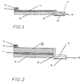
- FIG. 1 shows the layer structure of a first in a purely schematic representation Protective sheathing.
- This consists of an outer layer 10 in the form of a Velcro or velor tape made of an abrasion-resistant, resistant Material, preferably polyester.
- a hook tape fastened consisting of a carrier tape 15 with hooks 16.
- the carrier tape 15 overlaps the outer layer 10.
- the carrier tape 15 is at least partially made of the same thermoplastic material as the outer layer 10. This makes it possible to weld both layers 10, 15 without tools, either by ultrasound, by flame or by laser. This forms there is a continuous welding zone 18.
- the hooks 16 are covered by a protective film 17. This is after the Wrapped around the object to be protected, whereupon the hooks 16 hook with the outside of the fleece or velor ribbon 10 and so the Close protective jacket.
- Fig. 2 shows a second embodiment of a protective jacket.
- the inner layer additionally comprises a foam 12, preferably one Polyurethane foam.
- fleece 11 and Foam 12 by means of flame lamination creates a mixed layer. This bothers the welding zone 18 is not.
Landscapes
- Engineering & Computer Science (AREA)
- Architecture (AREA)
- Civil Engineering (AREA)
- Structural Engineering (AREA)
- Mechanical Engineering (AREA)
- Details Of Indoor Wiring (AREA)
- Laminated Bodies (AREA)
- Electric Cable Arrangement Between Relatively Moving Parts (AREA)
Abstract
Description
- Fig. 1
- eine erste Schutzummantelung und
- Fig. 2
- eine zweite Schutzummantelung.
Claims (10)
- Schutzummantelung für Kabel, Leitungen, Litzen, Hüllrohre und dergleichen langgestreckte, bewegliche Gegenstände, die in rotierenden bzw. vibrierenden Maschinen, Anlagen oder Fahrzeugen verlegt werden, insbesondere für Kabelbäume in Kraftfahrzeugen, in Waschmaschinen, in Kompressoren und dergleichen, im wesentlichen umfassendgekennzeichnet durch die Merkmale:eine abriebfeste, widerstandsfähige Außenschicht (10) aus einem Flausch-bzw. Veloursband,darauf kaschiert eine Innenschicht (11, 12),darauf entlang der einen Längskante des Bandes (10) kaschiert eine selbstklebende Schicht (13), gegebenenfalls abgedeckt mit einem Schutzpapier (14),und entlang der anderen Längskante des Bandes (10) befestigt ein Hakenband (15, 16),das Hakenband besteht aus einem Trägerband (15) und Haken (16),die Außenschicht (10) und das Trägerband (15) bestehen aus demselben thermoplastischen Kunststoff,Außenschicht (10) und Trägerband (15)überlappen sichund sind in der Überlappungszone (18) miteinander verschweißt.
- Schutzummantelung nach Anspruch 1, gekennzeichnet durch das Merkmal:Außenschicht (10) und Trägerband (15) sind mittels Ultraschall verschweißt.
- Schutzummantelung nach Anspruch 1, gekennzeichnet durch das Merkmal:Außenschicht (10) und Trägerband (15) sind mittels Laser verschweißt.
- Schutzummantelung nach einem der Ansprüche 1 bis 3, gekennzeichnet durch das Merkmal:die Innenschicht umfasst ein Vlies (11).
- Schutzummantelung nach einem der Ansprüche 1 bis 4, gekennzeichnet durch das Merkmal:die Innenschicht umfasst einen Schaumstoff (12).
- Schutzummantelung nach einem der Ansprüche 1 bis 4, gekennzeichnet durch das Merkmal:die Innenschicht ist ein Filz aus Naturwolle, synthetischen Fasern, keramischen Fasern oder Werkstoffen aus Glaswolle.
- Schutzummantelung nach Anspruch 4 oder 5, gekennzeichnet durch das Merkmal:Vlies (11) und/oder Schaumstoff (12) sind mit der Außenschicht (10) flammkaschiert.
- Schutzummantelung nach Anspruch 7, gekennzeichnet durch das Merkmal:Außenschicht (10) und Vlies (11) bzw. Schaumstoff (12) bestehen aus der gleichen Materialbasis.
- Schutzummantelung nach einem der Ansprüche 5 bis 8, gekennzeichnet durch das Merkmal:der Schaumstoff (12) besteht aus Polyurethan.
- Schutzummantelung nach einem der Ansprüche 1 bis 9, gekennzeichnet durch das Merkmal:das Hakenband (15, 16) ist mit einem Schutz (17) abgedeckt.
Applications Claiming Priority (2)
| Application Number | Priority Date | Filing Date | Title |
|---|---|---|---|
| DE20021786U | 2000-12-22 | ||
| DE20021786U DE20021786U1 (de) | 2000-12-22 | 2000-12-22 | Schutzummantelung für Kabel, Hüllrohre, Kabelbäume u.dgl. |
Publications (3)
| Publication Number | Publication Date |
|---|---|
| EP1217704A2 true EP1217704A2 (de) | 2002-06-26 |
| EP1217704A3 EP1217704A3 (de) | 2004-02-04 |
| EP1217704B1 EP1217704B1 (de) | 2006-06-28 |
Family
ID=7950479
Family Applications (1)
| Application Number | Title | Priority Date | Filing Date |
|---|---|---|---|
| EP01102448A Expired - Lifetime EP1217704B1 (de) | 2000-12-22 | 2001-02-03 | Schutzummantelung für Kabel, Hüllrohre, Kabelbäume und dergleichen |
Country Status (2)
| Country | Link |
|---|---|
| EP (1) | EP1217704B1 (de) |
| DE (2) | DE20021786U1 (de) |
Cited By (2)
| Publication number | Priority date | Publication date | Assignee | Title |
|---|---|---|---|---|
| EP1564321A1 (de) * | 2004-02-11 | 2005-08-17 | Fibertex A/S | Kabelschutz |
| EP1669653A1 (de) * | 2004-12-09 | 2006-06-14 | Bruno Behrens | Spritzschutz |
Families Citing this family (6)
| Publication number | Priority date | Publication date | Assignee | Title |
|---|---|---|---|---|
| FR2833679B1 (fr) † | 2001-12-18 | 2004-05-14 | Fed Mogul Systems Prot Group | Gaine de protection refermable par recouvrement et utilisation de cette gaine |
| DE20201644U1 (de) * | 2002-02-04 | 2002-06-20 | Ffa Automotive Ag, Altenrhein | Schutzummantelung |
| DE102004018844B9 (de) * | 2004-04-19 | 2006-06-01 | Polfin Ltd. | Vorrichtung zum Bündeln von Kabelbäumen |
| DE102014003211A1 (de) | 2014-03-07 | 2015-09-10 | Gottlieb Binder Gmbh & Co. Kg | Verbindungsverfahren nebst hierfür einsetzbarem Funktionsteil und danach hergestelltes schwerentflammbares Gesamtsystem |
| DE102017002902B4 (de) * | 2017-03-27 | 2026-04-02 | Iprotex Gmbh & Co. Kg | Textiler Schlauch |
| US12595597B2 (en) | 2022-03-18 | 2026-04-07 | Systems Protection Group Us Llc | Flexible, high temperature resistant, fluid resistant, abrasion resistant, multilayered wrappable textile sleeve and method of construction thereof |
Family Cites Families (3)
| Publication number | Priority date | Publication date | Assignee | Title |
|---|---|---|---|---|
| US3941159A (en) * | 1974-10-31 | 1976-03-02 | Wolcott Toll | Insulation assembly for a tubular conduit pipe |
| US4382303A (en) * | 1977-01-17 | 1983-05-10 | Lunt Audrey T | Non-woven polyester wearing apparel |
| DE29710582U1 (de) * | 1997-06-18 | 1998-09-10 | Mohr, Karl Eugen, 67466 Lambrecht | Schutzummantelung für Kabel, Litzen, Kabelbäume u.dgl. |
-
2000
- 2000-12-22 DE DE20021786U patent/DE20021786U1/de not_active Expired - Lifetime
-
2001
- 2001-02-03 EP EP01102448A patent/EP1217704B1/de not_active Expired - Lifetime
- 2001-02-03 DE DE50110326T patent/DE50110326D1/de not_active Expired - Fee Related
Cited By (2)
| Publication number | Priority date | Publication date | Assignee | Title |
|---|---|---|---|---|
| EP1564321A1 (de) * | 2004-02-11 | 2005-08-17 | Fibertex A/S | Kabelschutz |
| EP1669653A1 (de) * | 2004-12-09 | 2006-06-14 | Bruno Behrens | Spritzschutz |
Also Published As
| Publication number | Publication date |
|---|---|
| DE50110326D1 (de) | 2006-08-10 |
| EP1217704B1 (de) | 2006-06-28 |
| EP1217704A3 (de) | 2004-02-04 |
| DE20021786U1 (de) | 2001-03-15 |
Similar Documents
| Publication | Publication Date | Title |
|---|---|---|
| EP2627539B1 (de) | Klebeband sowie aus dem klebeband hergestellte schlauchummantelung | |
| EP2034576B1 (de) | Klebeband zur Längsummantelung von langgestrecktem Gut | |
| EP3245265B1 (de) | Klebeband, insbesondere wickelband | |
| EP0886358B1 (de) | Schutzummantelung für Kabel, Litzen, Kabelbäume und dergleichen | |
| EP0886357A2 (de) | Schutzummantelung für Kabel, Litzen, Kabelbäume und dergleichen | |
| DE10229527A1 (de) | Band aus einer Reihe hintereinander und überlappend angeordneter einzelner Ummantelungsabschnitte zum Ummanteln von langgestrecktem Gut, wie insbesondere Kabelsätzen | |
| DE29510907U1 (de) | Schutzummantelung für Kabel, Litzen u.dgl. | |
| EP3180405B1 (de) | Verfahren zur herstellung einer ummantelung für langgestrecktes gut | |
| DE102014113769A1 (de) | Verfahren zur Herstellung einer Ummantelung für langgestrecktes Gut | |
| EP1217704A2 (de) | Schutzummantelung für Kabel, Hüllrohre, Kabelbäume und dergleichen | |
| DE112012006247T5 (de) | Kabelstrang und Herstellungsverfahren für einen Kabelstrang | |
| WO2015052022A1 (de) | Umhüllungsmittel für ein langgestrecktes gut und dessen verwendung | |
| WO2009086570A1 (de) | Schutzvorrichtung | |
| EP1063747A1 (de) | Schutzummantelung | |
| EP1615238B1 (de) | Thermisch isolierendes technisches Klebeband sowie Kabelbaum hoher Temperaturbeständigkeit | |
| DE102018118778A1 (de) | Sicherheitsgurt mit elektrischer Einheit | |
| DE69605688T2 (de) | Längsgeschlitztes wellrohr mit schallisolierung | |
| AT505233B1 (de) | Schutzvorrichtung und transportvorrichtung | |
| DE10340180B4 (de) | Abriebschutzvorrichtung | |
| DE2913054C2 (de) | ||
| EP1258346A2 (de) | Schutzummantelung | |
| DE102004015019B3 (de) | Abriebschutzvorrichtung | |
| DE202007014344U1 (de) | Geflechtschlauch | |
| DE20111731U1 (de) | Abzweigelement für Schutzummantelungen | |
| DE10356973B3 (de) | Schutzummantelung für Kabelbäume von Kraftfahrzeugen |
Legal Events
| Date | Code | Title | Description |
|---|---|---|---|
| PUAI | Public reference made under article 153(3) epc to a published international application that has entered the european phase |
Free format text: ORIGINAL CODE: 0009012 |
|
| AK | Designated contracting states |
Kind code of ref document: A2 Designated state(s): AT BE CH CY DE DK ES FI FR GB GR IE IT LI LU MC NL PT SE TR |
|
| AX | Request for extension of the european patent |
Free format text: AL;LT;LV;MK;RO;SI |
|
| PUAL | Search report despatched |
Free format text: ORIGINAL CODE: 0009013 |
|
| AK | Designated contracting states |
Kind code of ref document: A3 Designated state(s): AT BE CH CY DE DK ES FI FR GB GR IE IT LI LU MC NL PT SE TR |
|
| AX | Request for extension of the european patent |
Extension state: AL LT LV MK RO SI |
|
| RIC1 | Information provided on ipc code assigned before grant |
Ipc: 7H 02G 3/04 A |
|
| 17P | Request for examination filed |
Effective date: 20040417 |
|
| AKX | Designation fees paid |
Designated state(s): DE ES FR GB PT |
|
| AXX | Extension fees paid |
Extension state: SI Payment date: 20040417 |
|
| 17Q | First examination report despatched |
Effective date: 20050314 |
|
| GRAP | Despatch of communication of intention to grant a patent |
Free format text: ORIGINAL CODE: EPIDOSNIGR1 |
|
| GRAS | Grant fee paid |
Free format text: ORIGINAL CODE: EPIDOSNIGR3 |
|
| GRAA | (expected) grant |
Free format text: ORIGINAL CODE: 0009210 |
|
| AK | Designated contracting states |
Kind code of ref document: B1 Designated state(s): DE ES FR GB PT |
|
| AX | Request for extension of the european patent |
Extension state: SI |
|
| PG25 | Lapsed in a contracting state [announced via postgrant information from national office to epo] |
Ref country code: GB Free format text: LAPSE BECAUSE OF FAILURE TO SUBMIT A TRANSLATION OF THE DESCRIPTION OR TO PAY THE FEE WITHIN THE PRESCRIBED TIME-LIMIT Effective date: 20060628 |
|
| REG | Reference to a national code |
Ref country code: GB Ref legal event code: FG4D Free format text: NOT ENGLISH |
|
| REF | Corresponds to: |
Ref document number: 50110326 Country of ref document: DE Date of ref document: 20060810 Kind code of ref document: P |
|
| PG25 | Lapsed in a contracting state [announced via postgrant information from national office to epo] |
Ref country code: ES Free format text: LAPSE BECAUSE OF FAILURE TO SUBMIT A TRANSLATION OF THE DESCRIPTION OR TO PAY THE FEE WITHIN THE PRESCRIBED TIME-LIMIT Effective date: 20061009 |
|
| PG25 | Lapsed in a contracting state [announced via postgrant information from national office to epo] |
Ref country code: PT Free format text: LAPSE BECAUSE OF FAILURE TO SUBMIT A TRANSLATION OF THE DESCRIPTION OR TO PAY THE FEE WITHIN THE PRESCRIBED TIME-LIMIT Effective date: 20061128 |
|
| GBV | Gb: ep patent (uk) treated as always having been void in accordance with gb section 77(7)/1977 [no translation filed] |
Effective date: 20060628 |
|
| PLBE | No opposition filed within time limit |
Free format text: ORIGINAL CODE: 0009261 |
|
| STAA | Information on the status of an ep patent application or granted ep patent |
Free format text: STATUS: NO OPPOSITION FILED WITHIN TIME LIMIT |
|
| EN | Fr: translation not filed | ||
| 26N | No opposition filed |
Effective date: 20070329 |
|
| PG25 | Lapsed in a contracting state [announced via postgrant information from national office to epo] |
Ref country code: DE Free format text: LAPSE BECAUSE OF NON-PAYMENT OF DUE FEES Effective date: 20070901 |
|
| PG25 | Lapsed in a contracting state [announced via postgrant information from national office to epo] |
Ref country code: FR Free format text: LAPSE BECAUSE OF FAILURE TO SUBMIT A TRANSLATION OF THE DESCRIPTION OR TO PAY THE FEE WITHIN THE PRESCRIBED TIME-LIMIT Effective date: 20070511 |
|
| PG25 | Lapsed in a contracting state [announced via postgrant information from national office to epo] |
Ref country code: FR Free format text: LAPSE BECAUSE OF FAILURE TO SUBMIT A TRANSLATION OF THE DESCRIPTION OR TO PAY THE FEE WITHIN THE PRESCRIBED TIME-LIMIT Effective date: 20060628 |