EP1217582A1 - Digital filter - Google Patents
Digital filter Download PDFInfo
- Publication number
- EP1217582A1 EP1217582A1 EP01908304A EP01908304A EP1217582A1 EP 1217582 A1 EP1217582 A1 EP 1217582A1 EP 01908304 A EP01908304 A EP 01908304A EP 01908304 A EP01908304 A EP 01908304A EP 1217582 A1 EP1217582 A1 EP 1217582A1
- Authority
- EP
- European Patent Office
- Prior art keywords
- coefficient
- data
- unit
- texture
- region
- Prior art date
- Legal status (The legal status is an assumption and is not a legal conclusion. Google has not performed a legal analysis and makes no representation as to the accuracy of the status listed.)
- Withdrawn
Links
Images





Classifications
-
- G—PHYSICS
- G06—COMPUTING OR CALCULATING; COUNTING
- G06T—IMAGE DATA PROCESSING OR GENERATION, IN GENERAL
- G06T5/00—Image enhancement or restoration
- G06T5/73—Deblurring; Sharpening
- G06T5/75—Unsharp masking
-
- G—PHYSICS
- G06—COMPUTING OR CALCULATING; COUNTING
- G06T—IMAGE DATA PROCESSING OR GENERATION, IN GENERAL
- G06T15/00—Three-dimensional [3D] image rendering
- G06T15/50—Lighting effects
- G06T15/503—Blending, e.g. for anti-aliasing
-
- G—PHYSICS
- G06—COMPUTING OR CALCULATING; COUNTING
- G06T—IMAGE DATA PROCESSING OR GENERATION, IN GENERAL
- G06T5/00—Image enhancement or restoration
- G06T5/20—Image enhancement or restoration using local operators
-
- H—ELECTRICITY
- H03—ELECTRONIC CIRCUITRY
- H03H—IMPEDANCE NETWORKS, e.g. RESONANT CIRCUITS; RESONATORS
- H03H17/00—Networks using digital techniques
- H03H17/02—Frequency selective networks
- H03H17/0219—Compensation of undesirable effects, e.g. quantisation noise, overflow
Definitions
- This invention relates to a digital filter and, particularly, to a digital filter used for an image processing.
- Digital filters such as convolution (convolutional processing) filter and the like filters have heretofore been used for an image processing.
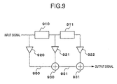
- Fig. 9 is a diagram illustrating the constitution of a conventional digital filter which includes delay units 910, 911, coefficient multiplier units 920, 921, 922 and adder units 930, 931.
- this digital filter an input signal and a signal obtained by delaying the input signal are multiplied by a predetermined coefficient, and an added result thereof is produced as an output signal.
- the digital filter repeats the sum-of-product operation in the process of calculation. Unless the calculation is conducted maintaining a sufficient degree of calculation precision (calculated word length), therefore, there often occurs cancellation of significant digits. In Fig. 9, for example, the cancellation occurs unless the operation units 920, 921, 922, 930, 931 and the region for holding intermediate data 950, 951 during the calculation have a sufficient word length. If such a digital filter is used for an image processing, therefore, the original image can not be reproduced in detail, and vivid gradation of the image is not obtainable.
- a digital filter comprises a filter operation unit for calculating a coefficient by effecting a sum-of-product operation for input data, and a multiplier unit for multiplying the coefficient calculated by the filter operation unit by the input data.
- a filter processing method comprises calculating a coefficient by executing a sum-of-product operation for input data, multiplying the calculated coefficient by the input data, and producing the multiplied result as output data.
- a recording medium is the one that records a program for effecting the filtering for image data.
- the program has a step of calculating a coefficient by executing a sum-of-product operation for the image data, a step of multiplying the calculated coefficient by the image data, and a step of producing the multiplied result.
- the program can be distributed with a portable recording medium such as CD-ROM, DVD-ROM or memory card, or through a network.
- An entertainment device includes a drawing operation unit and a drawing memory.
- the drawing memory includes a drawing region and a texture region.
- the drawing operation unit includes a texture mapping unit and a blending unit.
- the texture mapping unit executes texture mapping by using, as texture data, the image data stored in the texture region.
- the blending unit executes a mixed mode operation between the data after the texture-mapping and the data stored in the drawing region, stores the result in the drawing region thereby to calculate a coefficient used for image filter processing, and finds a product of the thus calculated coefficient and the image data.
- Fig. 1 is a diagram illustrating the constitution of a digital filter according to this invention.
- a digital filter 1 includes delay units 10, 11, coefficient multiplier units 20, 21, 22, 23, adder units 30, 31, 32, and an offset constant unit 40.
- an input signal is subjected to a filtering operation (sum-of-product operation) through the delay units 10, 11, coefficient multiplier units 20, 21, 22, adder units 30, 31, 32 and offset constant unit 40, thereby to find a coefficient.
- the thus found coefficient is multiplied by the original data through the coefficient multiplier unit 23 to obtain an output signal.
- the digital filter 1 firstly finds the coefficient from the input signal, and multiplies the original data by the coefficient in the final stage.
- the original data is multiplied only once in the final stage, and becomes little likely to be canceled.
- the original signals are reproducible in more detail compared to that of using the conventional digital filter shown in Fig. 9, and clear image gradation is accomplished.
- the edge-enhancing filter is for enhancing the edge of the reproduced DVD video image to meet the linking of a user.
- Fig. 2 is a block diagram illustrating the constitution of the entertainment device to which this invention is applied.
- the entertainment device executes a game fed by CD/DVD and reproduces the DVD video supplied by DVD.
- the entertainment device includes a main CPU 100, a graphic processor (GP) 110, an IOP 120, a CD/DVD reader unit 130, an SPU 140, an OSROM 150, a main memory 160, and an IOP memory 170.
- GP graphic processor
- the main CPU 100 and the graphic processor 110 are connected together through a dedicated bus 101.
- the main CPU 100 and the IOP 120 are connected together through a bus 102.
- the IOP 120, CD/DVD reader unit 130, SPU 140 and OSROM 150 are connected to a bus 103.
- the main memory 160 is connected to the main CPU 100, and the IOP memory 170 is connected to the IOP 120.
- a controller (PAD) 180 is connected to the IOP 120.
- the main CPU 100 executes a predetermined processing by executing a program stored in the OSROM 150 and by executing a program loaded onto the main memory 160 from a CD or a DVD (or a memory card that is not shown).
- the graphic processor 110 is a drawing processor which takes over the job of a rendering function of the entertainment device, and executes drawing processing according to instructions from the main CPU 100.
- the IOP 120 is an input/output sub-processor for controlling the exchange of data between the main CPU 100 and peripheral equipment (CD/DVD reader unit 130, SPU 140, etc.).
- the CD/DVD reader unit 130 reads data from the CD and DVD, and transfers the data to the main memory 160.
- the SPU 140 is a sound reproduction processor and reproduces the compressed waveform data stored in the sound buffer (not shown) at a predetermined sampling frequency based upon a sounding instruction from the main CPU 100 or the like.
- the OSROM 150 is a ROM storing a program executed by the main CPU 100 and the IOP 120 at the starting.
- the main memory 160 is a main memory for the main CPU 100, and stores instructions executed by the main CPU 100 and data utilized by the main CPU 100.
- the IOP memory 170 is a main memory for the IOP 120, and stores instructions executed by the IOP 120 and data utilized by the IOP 120.
- the controller (PAD) 180 is an interface for transmitting the will of the player to the application and the like while playing the game and the like.
- the edge-enhancing filter which enhances the edge for the DVD video output by utilizing the drawing function of the graphic processor 110 is mounted.
- edge-enhancing filter processing executed by utilizing the graphic processor 110 during the DVD video reproduction.
- Fig. 3 is a diagram illustrating the internal constitution of the graphic processor 110.
- the graphic processor 110 includes a host interface unit 400, a drawing function block 410, a local memory 420 and a CRTC unit 430.
- the host interface unit 400 works to exchange the data relative to the main CPU 100.
- the drawing function block 410 is a logic circuit unit that executes rendering in response to instructions from the main CPU 100.
- the drawing function block 410 includes 16 digital differential analyzers (DDAs) and 16 pixel engines, and processes in parallel a maximum of 16 pixel data of 64 bits (32 bits of colordata and 32 bits of Z value).
- the DDAs calculate RGB values, Z values, texture values and the like. Based upon these data, the pixel engines form final pixel data.
- the local memory 420 stores the pixel data formed by the drawing function block 410 and the texture data transferred from the main CPU 100.
- the CRTC unit 430 outputs, as video signals, the content of the frame buffer region of the local memory 420 according to an output format (NTSC, PAL, VESA format, etc.) that is specified.
- an output format (NTSC, PAL, VESA format, etc.) that is specified.
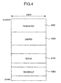
- Fig. 4 is a diagram illustrating the constitution of the local memory 420.
- the local memory 420 includes a frame buffer region 450, a Z-buffer region 460, a texture buffer region 470 and a texture CLUT region 480.
- the frame buffer region 450 and the Z-buffer region 460 are the regions for drawing; i.e., the frame buffer region 450 is for storing pixels of the drawn results, and the Z-buffer region 460 is for storing the Z values of the results of drawing.
- the texture buffer region 470 stores image data of the texture
- the texture CLUT region 480 stores a color look-up table (CLUT) that is used when the textures are index colors.
- the regions 450 to 480 can be freely arranged at any addresses in any order on the local memory 420.
- the DVD video reproduction processing is executed when, for example, a DVD reproduction software loaded onto the main memory 160 from a memory card is executed by the main CPU 100.
- the CD/DVD reader unit 130 When a DVD video reproduction is instructed by a user, the CD/DVD reader unit 130 reads the video data stored in the DVD, and transfers the video data that are read out to the main memory 160 via the IOP 120.
- the main CPU 100 subjects the video data (MPEG2 bit stream) stored in the main memory 160 to the MPEG2 decoding to, first, form image data (YCbCr pixel data) of the YCbCr format, then, executes color-space conversion, and forms image data (RGBA pixel data) of the RGB form.
- the thus formed image data of the RGB format are transferred to the graphic processor 110 so as to be displayed on a display unit.
- Y (brightness) data are also sent to the graphic processor 110 together with the RGB data.
- the data of a total of 32 bits, i.e., 8 bits for each of the pixels or RGBY, are transferred to the graphic processor 110.
- the RGB data and Y data sent to the graphic processor 110 are stored, as texture data, in the texture buffer region 470 of the local memory 420 in the graphic processor 110.
- Fig. 5 (a) is a diagram illustrating a format of storing the RGB data in the texture buffer region 470.
- data R is stored in the bits [7:0]
- data G is stored in the bits [15:8]
- data B is stored in the bits [23:16]
- data Y is stored in the bits [31:24].
- alpha data is stored in the bits [31:24].
- the graphic processor 110 supports plural formats for storing texture pixels in addition to the format shown in Fig. 5 (a) . These plural formats can be used being changed over by changing the setting of a particular control register.
- Fig. 5(b) is a diagram illustrating another format for storing texture pixels in the graphic processor 110.
- the upper 8 bits form an index for the color look-up table stored in the texture CLUT region 480.
- the color look-up table has 256 entries. A color value corresponding to the index value is stored in each entry of the color look-up table. The case of utilizing this format will be described later.
- the edge-enhancing processing is effected for the image data (RGBY data) transferred to the texture buffer region 470.
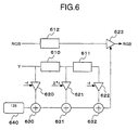
- Fig. 6 is a diagram illustrating an equivalent flow of the edge-enhancing filter according to this embodiment.
- the edge-enhancing filter is a convolution filter in the transverse (horizontal) direction only, and calculates the coefficient of filter processing by using brightness data of the right and left neighboring pixels.
- the edge-enhancing filter includes delay units 610, 611, 612, coefficient multiplier units 620, 621, 622, 623, adderunits 630, 631, 632, and the offset constant unit 640.
- each of RGB is multiplied by the same coefficient calculated from the data Y to find final values RGB, respectively.
- the digital filters illustrated in Fig. 1 are provided for each of RGB, and each of RGB may be multiplied by a separate coefficient calculated for each of RGB, to find final values RGB.
- the edge-enhancing filter for R works to multiply the input signal R by a coefficient calculated from R to obtain a final value R.
- RGBY are each constituted by 8 bits, and the coefficients in the coefficient multiplier units 620 to 623 are multiplied by using 8 bits x 8 bits multipliers.
- the addition is executed by using 8-bit adders.
- a value f is for controlling the intensity of edge enhancement and assumes from 0 to 64.
- the value f is set to an intensity preferred by the user.
- Fig. 7 is a diagram illustrating the outline of an image filter processing by using the graphic processor 110.
- a drawing function block 410 in the graphic processor 110 includes a texture mapping unit 411 and a blending unit 412.
- the filter processing is executed by utilizing the texture mapping function and the blending function of the graphic processor 110.
- image data (source data) of the RGBY format decoded by MPEG2 are transferred to the texture buffer region 470, and the drawing is processed by effecting the texture mapping turned on and the blending turned on.
- the texture mapping unit 411 thereby multiplies the source data by a predetermined coefficient.
- the blending unit 412 subjects the source data multiplied by the predetermined coefficient and the data (destination data) in the frame buffer region 450 to the mixed mode operation (addition and subtraction).
- the blending unit 412 writes the result into the frame buffer region 450.
- the texture mapping unit 411 and the blending unit 412 repeats the above processings.
- the graphic processor 110 effects the blending function to calculate the blending between an output color (source color) Cs after the texture mapping and a pixel color (destination color) Cd in the frame buffer region.
- the graphic processor 110 can suitably set the register for controlling the blending and vary A, B, C and D as described below.
- the input color values A, B and D there can be selected any one of the RGB values Cs of source, RGB values Cd on the frame buffer region or 0, respectively.
- the input ⁇ value C there can be selected any one of alpha value of source, alpha value on the frame buffer region, or a fixed alpha value set to the register for controlling the blending.
- the main CPU 100 realizes the filtering operation (sum-of-product operation) by executing a required blending processing by suitably setting a control register in the graphic processor 110.
- Fig. 8 is a diagram illustrating a group of commands which the main CPU 100 sends to the graphic processor 110 in executing the image filter processing.
- d* (dRGB, etc.) represents a destination surface
- s* (sY, etc.) represents a source surface.
- an edge-enhancing coefficient f is set (S1). For example, a value which the user has specified out of his liking is set.
- the processing is instructed to the graphic processor 110 in a unit of a plane.
- the offset value OFFX is set to be -1, and each of the pixels is operated by using brightness data of the left neighboring pixel (S3). That is, the brightness (Y) data of a pixel just on the left side of the pixel being processed is multiplied by the coefficient f, and the result is subtracted from the RGB value of the pixel being processed. This processing is also executed in a unit of a plane.
- the texture pixels stored in the texture buffer region 470 are treated as having a format shown in Fig. 5(b). That is, the Y value is treated as an index value of CLUT stored in the texture CLUT region 480, and the color values stored in the respective entries of CLUT are used for the practical processing.
- the value same as the index is input to each of the RGB of the entries (0 to 255), of the CLUT in advance.
- the offset value OFFX is returned to 0, and the operation is executed by using its own brightness data for each of the pixels (S4). That is, the brightness data of the pixel to be treated is multiplied by the coefficient f, and the result is added to the RGB values of the pixel being processed. This processing is also executed in a unit of a plane.
- the coefficient f assumes a value over a range of from 0 to 128, the dynamic range of f is guaranteed by dividing the operation which is added by being multiplied by 2f into two times of operations which are added by being multiplied by f.
- the addition is the first one.
- the offset value OFFX is set to be 1, and the operation is executed for each of the pixels by using brightness data of a pixel which is just on the right side (S5). That is, the brightness data of a pixel just on the right side of the pixel being processed is multiplied by the coefficient f, and the result is subtracted from the RGB values of the pixel being processed. This processing is also executed in a unit of a plane.
- the offset value OFFX is returned to 0, and the operation is executed by using its own brightness data for each of the pixels (S6). That is, the brightness data of the pixel being processed is multiplied by the coefficient f, and the result is added to the RGB values of the pixel being processed. The addition of this time is the second one of the operation that is added by being multiplied by 2f and is divided into two.
- the coefficient that is to be finally multiplied upon the original data is stored in the RGB values in the destination region.
- the coefficient is copied into the ⁇ surface (upper 8 bits) from the RGB surfaces of the destination region (S7).
- the same value has been stored in the RGB surfaces.
- the data of the G surface is copied onto the ⁇ surface.
- the RGB values obtained by subjecting the image data stored in the source region to the edge-enhancing filter processing are stored in the RGB surfaces in the destination region.
- the edge-enhancing filter is realized by using the graphic processor 110.
- the edge-enhancing filter maybe mounted by using a general-purpose DSP or a dedicated hardware.
- the coefficient is calculated and, finally, a product of the calculated coefficient and the original data is obtained, eliminating the cancellation of the original data and offering vivid gradation of the image.
- this invention makes it possible to realize a digital filter permitting the input data to be little canceled even by using an operation unit having a short word length.
Landscapes
- Engineering & Computer Science (AREA)
- Physics & Mathematics (AREA)
- General Physics & Mathematics (AREA)
- Theoretical Computer Science (AREA)
- Computer Hardware Design (AREA)
- Mathematical Physics (AREA)
- Computer Graphics (AREA)
- Image Processing (AREA)
- Image Generation (AREA)
- Cable Transmission Systems, Equalization Of Radio And Reduction Of Echo (AREA)
- Complex Calculations (AREA)
- Picture Signal Circuits (AREA)
Abstract
Description
A, B, D = input color values, and
C = input α value.
Claims (5)
- A digital filter comprisinga filter operation unit for calculating a coefficient by effecting a sum-of-product operation for input data, anda multiplier unit for multiplying the coefficient calculated by the filter operation unit by the input data.
- A filter processing method comprising the steps of:calculating a coefficient by executing a sum-of-product operation for input data;multiplying the calculated coefficient by the input data; andproducing the multiplied result as output data.
- A recording medium recording a program that effects the filter processing for image data, the program having:a step of calculating a coefficient by executing a sum-of-product operation for the image data;a step of multiplying the calculated coefficient by the image data; anda step of producing the multiplied result.
- A program that effects the filter processing for image data, and having:a step of calculating a coefficient by executing a sum-of-product operation for the image data;a step of multiplying the calculated coefficient by the image data; anda step of producing the multiplied result.
- An entertainment system including a drawing operation unit and a drawing memory;the drawing memory having a drawing region and a texture region;the drawing operation unit including a texture mapping unit and a blending unit;the texture mapping unit executing texture mapping by using, as texture data, the image data stored in the texture region; andthe blending unit executing a mixed mode operation between the data after the texture-mapping and the data stored in the drawing region, and storing the result in the drawing region thereby to calculate a coefficient used for filtering the image and to find a product of the thus calculated coefficient and the image data.
Priority Applications (1)
| Application Number | Priority Date | Filing Date | Title |
|---|---|---|---|
| EP06006856A EP1669927A1 (en) | 2000-03-03 | 2001-03-05 | Brightness value blending method and entertainment system with drawing operation |
Applications Claiming Priority (3)
| Application Number | Priority Date | Filing Date | Title |
|---|---|---|---|
| JP2000059349A JP2001250115A (en) | 2000-03-03 | 2000-03-03 | Digital filter |
| JP2000059349 | 2000-03-03 | ||
| PCT/JP2001/001681 WO2001065485A1 (en) | 2000-03-03 | 2001-03-05 | Digital filter |
Related Child Applications (1)
| Application Number | Title | Priority Date | Filing Date |
|---|---|---|---|
| EP06006856A Division EP1669927A1 (en) | 2000-03-03 | 2001-03-05 | Brightness value blending method and entertainment system with drawing operation |
Publications (2)
| Publication Number | Publication Date |
|---|---|
| EP1217582A1 true EP1217582A1 (en) | 2002-06-26 |
| EP1217582A4 EP1217582A4 (en) | 2003-03-12 |
Family
ID=18579812
Family Applications (2)
| Application Number | Title | Priority Date | Filing Date |
|---|---|---|---|
| EP06006856A Withdrawn EP1669927A1 (en) | 2000-03-03 | 2001-03-05 | Brightness value blending method and entertainment system with drawing operation |
| EP01908304A Withdrawn EP1217582A4 (en) | 2000-03-03 | 2001-03-05 | Digital filter |
Family Applications Before (1)
| Application Number | Title | Priority Date | Filing Date |
|---|---|---|---|
| EP06006856A Withdrawn EP1669927A1 (en) | 2000-03-03 | 2001-03-05 | Brightness value blending method and entertainment system with drawing operation |
Country Status (13)
| Country | Link |
|---|---|
| US (1) | US6892214B2 (en) |
| EP (2) | EP1669927A1 (en) |
| JP (1) | JP2001250115A (en) |
| KR (1) | KR20020021788A (en) |
| CN (1) | CN1366650A (en) |
| AU (1) | AU3608401A (en) |
| BR (1) | BR0104869A (en) |
| CA (1) | CA2370723A1 (en) |
| MX (1) | MXPA01011128A (en) |
| NZ (1) | NZ515834A (en) |
| RU (1) | RU2001132755A (en) |
| TW (1) | TW530245B (en) |
| WO (1) | WO2001065485A1 (en) |
Families Citing this family (6)
| Publication number | Priority date | Publication date | Assignee | Title |
|---|---|---|---|---|
| JP4982080B2 (en) * | 2005-12-16 | 2012-07-25 | パナソニック株式会社 | Digital filter |
| RU2332716C2 (en) * | 2006-08-29 | 2008-08-27 | Самсунг Электроникс Ко., Лтд. | Method and device for anisotropic filtering of dynamic video picture |
| RU2411584C2 (en) * | 2008-08-21 | 2011-02-10 | Корпорация "САМСУНГ ЭЛЕКТРОНИКС Ко., Лтд." | Method of adaptive smoothing to suppress screen-type pattern of images |
| RU2408076C1 (en) * | 2009-07-02 | 2010-12-27 | Корпорация "САМСУНГ ЭЛЕКТРОНИКС Ко., Лтд." | Image compression method |
| HK1202964A1 (en) | 2011-11-29 | 2015-10-09 | Thomson Licensing | Texture masking for video quality measurement |
| RU2631976C2 (en) * | 2016-03-15 | 2017-09-29 | Федеральное государственное бюджетное образовательное учреждение высшего образования Московский авиационный институт (национальный исследовательский университет) (МАИ) | Tunable digital filter with programmable structure |
Family Cites Families (10)
| Publication number | Priority date | Publication date | Assignee | Title |
|---|---|---|---|---|
| JPH0620239B2 (en) | 1984-11-19 | 1994-03-16 | 株式会社リコー | Image processing device for electrophotographic printer |
| JPS61189719A (en) | 1985-02-18 | 1986-08-23 | Nec Corp | Non-cyclic digital filter |
| US5146470A (en) * | 1989-09-28 | 1992-09-08 | Fujitsu Limited | Adaptive digital filter including low-pass filter |
| US5262972A (en) * | 1991-07-17 | 1993-11-16 | Hughes Missile Systems Company | Multichannel digital filter apparatus and method |
| US5282155A (en) * | 1992-11-19 | 1994-01-25 | Bell Communications Resarch, Inc. | Adaptive digital filter architecture for parallel output/update computations |
| JPH06161876A (en) | 1992-11-24 | 1994-06-10 | Sony Corp | Image processing method |
| US5774125A (en) | 1993-11-18 | 1998-06-30 | Sony Corporation | Texture mapping method in which 3-D image data is transformed into 2-D data and mapped onto a surface of an object for display |
| JPH09116387A (en) | 1995-10-13 | 1997-05-02 | Ricoh Co Ltd | Digital filter |
| US5740343A (en) | 1995-11-03 | 1998-04-14 | 3Dfx Interactive, Incorporated | Texture compositing apparatus and method |
| JP3885262B2 (en) | 1996-12-17 | 2007-02-21 | 株式会社セガ | Method for mixing a plurality of pixels on a texture map, and a plurality of pixel mixing circuit and image processing apparatus using the same |
-
2000
- 2000-03-03 JP JP2000059349A patent/JP2001250115A/en active Pending
-
2001
- 2001-03-02 US US09/797,873 patent/US6892214B2/en not_active Expired - Lifetime
- 2001-03-05 NZ NZ515834A patent/NZ515834A/en not_active IP Right Cessation
- 2001-03-05 AU AU36084/01A patent/AU3608401A/en not_active Abandoned
- 2001-03-05 BR BR0104869-4A patent/BR0104869A/en not_active Application Discontinuation
- 2001-03-05 CA CA002370723A patent/CA2370723A1/en not_active Abandoned
- 2001-03-05 WO PCT/JP2001/001681 patent/WO2001065485A1/en not_active Ceased
- 2001-03-05 TW TW090105042A patent/TW530245B/en not_active IP Right Cessation
- 2001-03-05 RU RU2001132755/09A patent/RU2001132755A/en not_active Application Discontinuation
- 2001-03-05 EP EP06006856A patent/EP1669927A1/en not_active Withdrawn
- 2001-03-05 EP EP01908304A patent/EP1217582A4/en not_active Withdrawn
- 2001-03-05 CN CN01800892A patent/CN1366650A/en active Pending
- 2001-03-05 MX MXPA01011128A patent/MXPA01011128A/en unknown
- 2001-03-05 KR KR1020017013881A patent/KR20020021788A/en not_active Abandoned
Also Published As
| Publication number | Publication date |
|---|---|
| US6892214B2 (en) | 2005-05-10 |
| MXPA01011128A (en) | 2002-06-04 |
| EP1669927A1 (en) | 2006-06-14 |
| NZ515834A (en) | 2003-04-29 |
| TW530245B (en) | 2003-05-01 |
| AU3608401A (en) | 2001-09-12 |
| WO2001065485A1 (en) | 2001-09-07 |
| KR20020021788A (en) | 2002-03-22 |
| CN1366650A (en) | 2002-08-28 |
| CA2370723A1 (en) | 2001-09-07 |
| RU2001132755A (en) | 2003-08-20 |
| JP2001250115A (en) | 2001-09-14 |
| EP1217582A4 (en) | 2003-03-12 |
| US20010039556A1 (en) | 2001-11-08 |
| BR0104869A (en) | 2002-05-14 |
Similar Documents
| Publication | Publication Date | Title |
|---|---|---|
| US9483848B2 (en) | Image processing apparatus having a plurality of image processing blocks that are capable of real-time processing of an image signal | |
| US5798753A (en) | Color format conversion in a parallel processor | |
| US5936683A (en) | YUV-to-RGB conversion without multiplies using look-up tables and pre-clipping | |
| JP2001275015A (en) | Image processing circuit and image processing method | |
| US20110134291A1 (en) | Image-processing device for color image data and method for the image processing of color image data | |
| US6892214B2 (en) | Digital filter and method for producing an output by multiplying an input data unit only once by a coefficient | |
| US20070279434A1 (en) | Image processing device executing filtering process on graphics and method for image processing | |
| JP2001014454A (en) | Picture processor | |
| EP1320253A2 (en) | Colour transformation in 3D colour space | |
| JPH09101771A (en) | Image processing device | |
| US7372989B2 (en) | Color misregistration reducer | |
| JP2001197321A (en) | Color picture processing method and picture processor | |
| JP4215014B2 (en) | Image processing apparatus and image processing program | |
| JP2003338732A (en) | Digital filter | |
| JP2774879B2 (en) | Color correction circuit | |
| JP3641402B2 (en) | Color correction circuit and color correction method | |
| JP2001086353A (en) | Image processing method and apparatus | |
| JP2000253267A (en) | Method and device for color image processing | |
| JP3361833B2 (en) | Matrix circuit | |
| JP4774616B2 (en) | Image processing apparatus and image processing system | |
| JP2789726B2 (en) | Color image enhancement circuit | |
| JPH02312486A (en) | Picture data processing unit | |
| JPH01319877A (en) | image filter | |
| JPH04194984A (en) | image display device | |
| JP2002245483A (en) | Device and method for image processing, and program thereof |
Legal Events
| Date | Code | Title | Description |
|---|---|---|---|
| PUAI | Public reference made under article 153(3) epc to a published international application that has entered the european phase |
Free format text: ORIGINAL CODE: 0009012 |
|
| 17P | Request for examination filed |
Effective date: 20020227 |
|
| AK | Designated contracting states |
Kind code of ref document: A1 Designated state(s): AT BE CH CY DE DK ES FI FR GB GR IE IT LI LU MC NL PT SE TR |
|
| AX | Request for extension of the european patent |
Free format text: AL;LT;LV;MK;RO;SI |
|
| RIN1 | Information on inventor provided before grant (corrected) |
Inventor name: AOKI,SACHIYO, SONY COMPUTER ENTERTAINMENT INC. Inventor name: OHBA, AKIO, C/O SONY COMPUTER ENTERTAINMENT INC. |
|
| A4 | Supplementary search report drawn up and despatched |
Effective date: 20030123 |
|
| 17Q | First examination report despatched |
Effective date: 20040413 |
|
| STAA | Information on the status of an ep patent application or granted ep patent |
Free format text: STATUS: THE APPLICATION IS DEEMED TO BE WITHDRAWN |
|
| 18D | Application deemed to be withdrawn |
Effective date: 20060422 |