EP1217216B1 - Compressor lubrication control - Google Patents
Compressor lubrication control Download PDFInfo
- Publication number
- EP1217216B1 EP1217216B1 EP01310385A EP01310385A EP1217216B1 EP 1217216 B1 EP1217216 B1 EP 1217216B1 EP 01310385 A EP01310385 A EP 01310385A EP 01310385 A EP01310385 A EP 01310385A EP 1217216 B1 EP1217216 B1 EP 1217216B1
- Authority
- EP
- European Patent Office
- Prior art keywords
- viscosity
- compressor
- minimum
- unloader valve
- bearings
- Prior art date
- Legal status (The legal status is an assumption and is not a legal conclusion. Google has not performed a legal analysis and makes no representation as to the accuracy of the status listed.)
- Expired - Lifetime
Links
- 238000005461 lubrication Methods 0.000 title 1
- 239000000314 lubricant Substances 0.000 claims description 15
- 238000000034 method Methods 0.000 claims description 5
- 238000012544 monitoring process Methods 0.000 claims description 3
- 239000003921 oil Substances 0.000 description 12
- 239000003507 refrigerant Substances 0.000 description 11
- 230000008859 change Effects 0.000 description 5
- 230000009471 action Effects 0.000 description 4
- 230000007423 decrease Effects 0.000 description 4
- 230000001351 cycling effect Effects 0.000 description 2
- 238000009413 insulation Methods 0.000 description 2
- 239000010687 lubricating oil Substances 0.000 description 2
- 238000012986 modification Methods 0.000 description 2
- 230000004048 modification Effects 0.000 description 2
- 238000004378 air conditioning Methods 0.000 description 1
- 230000008901 benefit Effects 0.000 description 1
- 230000003247 decreasing effect Effects 0.000 description 1
- 230000001419 dependent effect Effects 0.000 description 1
- 230000001627 detrimental effect Effects 0.000 description 1
- 230000000694 effects Effects 0.000 description 1
- 239000007788 liquid Substances 0.000 description 1
- 239000002184 metal Substances 0.000 description 1
- 239000000203 mixture Substances 0.000 description 1
- 238000011144 upstream manufacturing Methods 0.000 description 1
Images

Classifications
-
- F—MECHANICAL ENGINEERING; LIGHTING; HEATING; WEAPONS; BLASTING
- F01—MACHINES OR ENGINES IN GENERAL; ENGINE PLANTS IN GENERAL; STEAM ENGINES
- F01M—LUBRICATING OF MACHINES OR ENGINES IN GENERAL; LUBRICATING INTERNAL COMBUSTION ENGINES; CRANKCASE VENTILATING
- F01M11/00—Component parts, details or accessories, not provided for in, or of interest apart from, groups F01M1/00 - F01M9/00
- F01M11/10—Indicating devices; Other safety devices
- F01M11/12—Indicating devices; Other safety devices concerning lubricant level
-
- F—MECHANICAL ENGINEERING; LIGHTING; HEATING; WEAPONS; BLASTING
- F04—POSITIVE - DISPLACEMENT MACHINES FOR LIQUIDS; PUMPS FOR LIQUIDS OR ELASTIC FLUIDS
- F04C—ROTARY-PISTON, OR OSCILLATING-PISTON, POSITIVE-DISPLACEMENT MACHINES FOR LIQUIDS; ROTARY-PISTON, OR OSCILLATING-PISTON, POSITIVE-DISPLACEMENT PUMPS
- F04C28/00—Control of, monitoring of, or safety arrangements for, pumps or pumping installations specially adapted for elastic fluids
- F04C28/06—Control of, monitoring of, or safety arrangements for, pumps or pumping installations specially adapted for elastic fluids specially adapted for stopping, starting, idling or no-load operation
-
- F—MECHANICAL ENGINEERING; LIGHTING; HEATING; WEAPONS; BLASTING
- F04—POSITIVE - DISPLACEMENT MACHINES FOR LIQUIDS; PUMPS FOR LIQUIDS OR ELASTIC FLUIDS
- F04C—ROTARY-PISTON, OR OSCILLATING-PISTON, POSITIVE-DISPLACEMENT MACHINES FOR LIQUIDS; ROTARY-PISTON, OR OSCILLATING-PISTON, POSITIVE-DISPLACEMENT PUMPS
- F04C23/00—Combinations of two or more pumps, each being of rotary-piston or oscillating-piston type, specially adapted for elastic fluids; Pumping installations specially adapted for elastic fluids; Multi-stage pumps specially adapted for elastic fluids
- F04C23/008—Hermetic pumps
-
- F—MECHANICAL ENGINEERING; LIGHTING; HEATING; WEAPONS; BLASTING
- F04—POSITIVE - DISPLACEMENT MACHINES FOR LIQUIDS; PUMPS FOR LIQUIDS OR ELASTIC FLUIDS
- F04C—ROTARY-PISTON, OR OSCILLATING-PISTON, POSITIVE-DISPLACEMENT MACHINES FOR LIQUIDS; ROTARY-PISTON, OR OSCILLATING-PISTON, POSITIVE-DISPLACEMENT PUMPS
- F04C28/00—Control of, monitoring of, or safety arrangements for, pumps or pumping installations specially adapted for elastic fluids
- F04C28/24—Control of, monitoring of, or safety arrangements for, pumps or pumping installations specially adapted for elastic fluids characterised by using valves controlling pressure or flow rate, e.g. discharge valves or unloading valves
- F04C28/26—Control of, monitoring of, or safety arrangements for, pumps or pumping installations specially adapted for elastic fluids characterised by using valves controlling pressure or flow rate, e.g. discharge valves or unloading valves using bypass channels
-
- F—MECHANICAL ENGINEERING; LIGHTING; HEATING; WEAPONS; BLASTING
- F04—POSITIVE - DISPLACEMENT MACHINES FOR LIQUIDS; PUMPS FOR LIQUIDS OR ELASTIC FLUIDS
- F04C—ROTARY-PISTON, OR OSCILLATING-PISTON, POSITIVE-DISPLACEMENT MACHINES FOR LIQUIDS; ROTARY-PISTON, OR OSCILLATING-PISTON, POSITIVE-DISPLACEMENT PUMPS
- F04C29/00—Component parts, details or accessories of pumps or pumping installations, not provided for in groups F04C18/00 - F04C28/00
- F04C29/02—Lubrication; Lubricant separation
- F04C29/021—Control systems for the circulation of the lubricant
-
- F—MECHANICAL ENGINEERING; LIGHTING; HEATING; WEAPONS; BLASTING
- F04—POSITIVE - DISPLACEMENT MACHINES FOR LIQUIDS; PUMPS FOR LIQUIDS OR ELASTIC FLUIDS
- F04C—ROTARY-PISTON, OR OSCILLATING-PISTON, POSITIVE-DISPLACEMENT MACHINES FOR LIQUIDS; ROTARY-PISTON, OR OSCILLATING-PISTON, POSITIVE-DISPLACEMENT PUMPS
- F04C18/00—Rotary-piston pumps specially adapted for elastic fluids
- F04C18/02—Rotary-piston pumps specially adapted for elastic fluids of arcuate-engagement type, i.e. with circular translatory movement of co-operating members, each member having the same number of teeth or tooth-equivalents
- F04C18/0207—Rotary-piston pumps specially adapted for elastic fluids of arcuate-engagement type, i.e. with circular translatory movement of co-operating members, each member having the same number of teeth or tooth-equivalents both members having co-operating elements in spiral form
- F04C18/0215—Rotary-piston pumps specially adapted for elastic fluids of arcuate-engagement type, i.e. with circular translatory movement of co-operating members, each member having the same number of teeth or tooth-equivalents both members having co-operating elements in spiral form where only one member is moving
-
- F—MECHANICAL ENGINEERING; LIGHTING; HEATING; WEAPONS; BLASTING
- F04—POSITIVE - DISPLACEMENT MACHINES FOR LIQUIDS; PUMPS FOR LIQUIDS OR ELASTIC FLUIDS
- F04C—ROTARY-PISTON, OR OSCILLATING-PISTON, POSITIVE-DISPLACEMENT MACHINES FOR LIQUIDS; ROTARY-PISTON, OR OSCILLATING-PISTON, POSITIVE-DISPLACEMENT PUMPS
- F04C2210/00—Fluid
- F04C2210/14—Lubricant
-
- F—MECHANICAL ENGINEERING; LIGHTING; HEATING; WEAPONS; BLASTING
- F04—POSITIVE - DISPLACEMENT MACHINES FOR LIQUIDS; PUMPS FOR LIQUIDS OR ELASTIC FLUIDS
- F04C—ROTARY-PISTON, OR OSCILLATING-PISTON, POSITIVE-DISPLACEMENT MACHINES FOR LIQUIDS; ROTARY-PISTON, OR OSCILLATING-PISTON, POSITIVE-DISPLACEMENT PUMPS
- F04C2210/00—Fluid
- F04C2210/40—Properties
- F04C2210/44—Viscosity
-
- F—MECHANICAL ENGINEERING; LIGHTING; HEATING; WEAPONS; BLASTING
- F04—POSITIVE - DISPLACEMENT MACHINES FOR LIQUIDS; PUMPS FOR LIQUIDS OR ELASTIC FLUIDS
- F04C—ROTARY-PISTON, OR OSCILLATING-PISTON, POSITIVE-DISPLACEMENT MACHINES FOR LIQUIDS; ROTARY-PISTON, OR OSCILLATING-PISTON, POSITIVE-DISPLACEMENT PUMPS
- F04C2240/00—Components
- F04C2240/60—Shafts
- F04C2240/603—Shafts with internal channels for fluid distribution, e.g. hollow shaft
-
- Y—GENERAL TAGGING OF NEW TECHNOLOGICAL DEVELOPMENTS; GENERAL TAGGING OF CROSS-SECTIONAL TECHNOLOGIES SPANNING OVER SEVERAL SECTIONS OF THE IPC; TECHNICAL SUBJECTS COVERED BY FORMER USPC CROSS-REFERENCE ART COLLECTIONS [XRACs] AND DIGESTS
- Y10—TECHNICAL SUBJECTS COVERED BY FORMER USPC
- Y10S—TECHNICAL SUBJECTS COVERED BY FORMER USPC CROSS-REFERENCE ART COLLECTIONS [XRACs] AND DIGESTS
- Y10S417/00—Pumps
- Y10S417/902—Hermetically sealed motor pump unit
Definitions
- This invention relates to a system which monitors the viscosity of the lubricant in a compressor and takes corrective action should that viscosity fall below a desired level.
- Compressors as typically utilized to compress a refrigerant such as in an air conditioning system are typically sealed in a housing.
- a suction refrigerant passing to the compressor will often pass within the interior of the housing and over the compressor motor through a suction port in a compressor pump unit.
- the refrigerant is compressed and driven through an outlet port to a downstream location such as a condenser.
- Compressors are often provided with a passage which selectively connects the discharge passage back to the suction passage.
- a valve typically closes the connecting passage, but may be selectively opened under certain system conditions. This valve is typically known as an unloader valve.
- a motor is typically housed within the sealed housing, and drives the compressor pump unit.
- a series of bearings supports a shaft driven by the motor to drive the compressor pump unit.
- These bearings are typically provided with a lubricant which is received in a sump in the housing, and which is driven throughout the housing during operation of the compressor. The lubricant serves to cool and lubricate the bearings.
- the viscosity of the lubricant can change.
- the necessary or minimum viscosity which would be desirable at the bearings will also vary as the operating conditions of the compressor change.
- a desired minimum viscosity of lubricant will also change.
- the viscosity of the lubricating oil has sometimes become too low to adequately lubricate the bearings. Bearing damage and subsequent failure has sometimes resulted.
- refrigerant also circulates with the lubricating oil.
- the oil can sometimes be diluted by liquid refrigerant, which can also lower the viscosity of the mixture.
- the viscosity relates to a minimum oil thickness at the bearings.
- the compressor bearings which are typically journal bearings, depend on a hydrodynamic oil film to prevent metal-to-metal contact.
- the necessary oil film thickness is dependent on a number of factors including the dimension of the bearings, the speed of the shaft rotation, the viscosity of the oil and the load on the bearing.
- the several variables which interact as described above have sometimes resulted in the viscosity of the oil being insufficient to adequately protect a bearing.
- the present invention is directed to addressing the situation when the viscosity of the lubricant in a sealed compressor becomes too low.
- JP 2000-120542 discloses a compressor comprising a sensor for measuring the insulation resistance between the sensor and the compressor. A heater is activated if the insulation resistance is lower than a predetermined value.
- a control monitors the viscosity of the oil.
- the control is provided with a minimum viscosity for the particular compressor. If the detected viscosity drops below the minimum required viscosity, some corrective action is taken by the control.
- an unloader valve is opened. When the unloader valve is opened, the load on the compressor significantly decreases. This thus reduces the required viscosity and reduces the likelihood of any bearing damage due to the low viscosity. Also, unloaded operation may allow the viscosity to increase.
- the viscosity of the oil in a compressor is periodically measured.
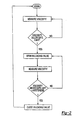
- the measured viscosity is compared to a minimum viscosity value. If the detected viscosity is above the minimum value, sensing simply continues. If however the viscosity is below a safe limit, then a corrective action is taken. While the corrective action can be as simple as stopping operation of the motor, in a preferred embodiment an unloader valve is opened. After the unloader valve is opened, the viscosity continues to be measured. Once the viscosity again increases above a safe limit, the unloader valve may be closed and the system can return to normal monitoring operation.
- control also monitors aspects of the operation of the compressor such as the speed, etc. to define the minimum viscosity value.
- the controller will typically be designed for each individual compressor such that the controller and its minimum viscosity values take into account the specific geometry etc. of the bearings utilized in the particular compressor.
- a compressor 20 incorporates a compressor pump unit 22 received within a sealed housing 24.
- An electric motor 25 drives a shaft 32 to rotate and drive the compressor pump unit.
- Bearings 28 and 30 mount the shaft within a housing.
- a discharge port 34 leads to a downstream user of the compressed refrigerant, typically a condenser.
- a suction port 36 leads from an upstream refrigerant cycle component, typically the condenser or an intermediate suction valve.
- an unloader passage 38 selectively communicates the discharge passage 34 to the suction passage 36. While the passage is shown external to the housing 24, such passages are often incorporated into the housing.
- a valve 40 is placed on the passage 38 and communicates with a controller 44. The valve may be selectively open to communicate discharge compressed refrigerant from passage 34 back to suction passage 36. The unloader valve is opened during typical cycling of the compressor when the necessary refrigerant load is low. Thus, if the necessary amount of compressed refrigerant decreases the unloader valve 40 may be opened to decrease the amount of refrigerant which is compressed.
- the preferred embodiment utilizes the opening of the valve to correct an undesirable system condition.
- a oil sump 26 is found within the housing 24 and contains a lubricant.
- a viscosity sensor 42 communicates with controller 44, and measures the viscosity of the lubricant. While the viscosity sensor 42 is shown within the sump 26 other locations may perhaps be utilized for the sensor.
- the sensor communicates the viscosity level of the oil to the controller.
- the controller will compare that viscosity level to a predetermined minimum viscosity level for safe operation of the compressor and protection of the bearings 28 and 30. If the viscosity level falls below the minimum level, then the unloader valve 40 is opened. While a first type of rotary compressor (a scroll compressor) is illustrated in Figure 1, it should be understood that the present invention would have application in any type of sealed compressor.
- the Sommerfeld number can be associated with a minimum film thickness variable of the oil or lubricant, which relates the ratio of the oil film thickness to a bearing clearance. As the Sommerfeld number increases, the minimum film thickness relative to the bearing clearance also increases. However, as is clear from the equation, if the bearing load decreases with decreasing viscosity, the Sommerfeld number can be held constant.
- the rotation speed of the shaft also has some effect in the minimum viscosity.
- the controller 44 may be sophisticated enough such that it takes in a speed input, or some related feedback, and changes the minimum viscosity to actuate the unloader based upon this detected variable.
- the minimum viscosity could be a set value for the particular compressor.
- a method of operating this invention begins with the step of measuring the viscosity, which is done on an ongoing basis. If the viscosity is determined to be above a safe limit, the system continues in a closed loop. If however the viscosity is determined to be below a safe limit, the unloader valve is opened. The viscosity continues to be measured with the unloader valve opened. If the viscosity remains below the safe limit, then the unloader valve is maintained open. Once the viscosity again moves above the safe limit, the controller 44 closes the unloader valve and returns to normal monitoring operation. As noted in the flowchart, the second step of determining the viscosity safe limit would include a hysteresis number to prevent excessive cycling of the unloader valve.
- the present invention is directed to addressing any potential detrimental effect from lower viscosity in a compressor lubricant. While preferred embodiments of this invention have been disclosed it should be understood that several modifications would come within the scope of this invention. As simple and very apparent modifications, other types of sealed compressors may benefit from this invention. In arrangements not within the scope of the present invention other control functions, such as simply stopping operation of the motor 25, may replace the opening of the unloader valve.
Landscapes
- Engineering & Computer Science (AREA)
- Mechanical Engineering (AREA)
- General Engineering & Computer Science (AREA)
- Physics & Mathematics (AREA)
- Fluid Mechanics (AREA)
- Compressor (AREA)
- Applications Or Details Of Rotary Compressors (AREA)
- Control Of Positive-Displacement Pumps (AREA)
Priority Applications (1)
| Application Number | Priority Date | Filing Date | Title |
|---|---|---|---|
| EP05017728A EP1598557B1 (en) | 2000-12-15 | 2001-12-12 | Compressor lubrication control |
Applications Claiming Priority (2)
| Application Number | Priority Date | Filing Date | Title |
|---|---|---|---|
| US738680 | 2000-12-15 | ||
| US09/738,680 US6431843B1 (en) | 2000-12-15 | 2000-12-15 | Method of ensuring optimum viscosity to compressor bearing system |
Related Child Applications (1)
| Application Number | Title | Priority Date | Filing Date |
|---|---|---|---|
| EP05017728A Division EP1598557B1 (en) | 2000-12-15 | 2001-12-12 | Compressor lubrication control |
Publications (3)
| Publication Number | Publication Date |
|---|---|
| EP1217216A2 EP1217216A2 (en) | 2002-06-26 |
| EP1217216A3 EP1217216A3 (en) | 2004-01-14 |
| EP1217216B1 true EP1217216B1 (en) | 2005-10-26 |
Family
ID=24969028
Family Applications (2)
| Application Number | Title | Priority Date | Filing Date |
|---|---|---|---|
| EP01310385A Expired - Lifetime EP1217216B1 (en) | 2000-12-15 | 2001-12-12 | Compressor lubrication control |
| EP05017728A Expired - Lifetime EP1598557B1 (en) | 2000-12-15 | 2001-12-12 | Compressor lubrication control |
Family Applications After (1)
| Application Number | Title | Priority Date | Filing Date |
|---|---|---|---|
| EP05017728A Expired - Lifetime EP1598557B1 (en) | 2000-12-15 | 2001-12-12 | Compressor lubrication control |
Country Status (6)
| Country | Link |
|---|---|
| US (1) | US6431843B1 (cg-RX-API-DMAC7.html) |
| EP (2) | EP1217216B1 (cg-RX-API-DMAC7.html) |
| JP (1) | JP2002206486A (cg-RX-API-DMAC7.html) |
| KR (1) | KR100412756B1 (cg-RX-API-DMAC7.html) |
| AU (1) | AU756028B2 (cg-RX-API-DMAC7.html) |
| DE (2) | DE60132721T2 (cg-RX-API-DMAC7.html) |
Families Citing this family (14)
| Publication number | Priority date | Publication date | Assignee | Title |
|---|---|---|---|---|
| BRPI0501446A (pt) * | 2005-04-29 | 2006-12-12 | Brasil Compressores Sa | método de proteção contra quebra do filme de óleo lubrificante nos mancais de compressores herméticos |
| US7980265B2 (en) * | 2007-12-06 | 2011-07-19 | Baker Hughes Incorporated | Valve responsive to fluid properties |
| US9341187B2 (en) | 2013-08-30 | 2016-05-17 | Emerson Climate Technologies, Inc. | Compressor assembly with liquid sensor |
| EP3084217B1 (en) | 2013-12-18 | 2020-08-12 | Carrier Corporation | Method of improving compressor bearing reliability |
| US10302340B2 (en) * | 2015-03-11 | 2019-05-28 | Emerson Climate Technologies, Inc. | Compressor having lubricant management system for bearing life |
| US10125768B2 (en) | 2015-04-29 | 2018-11-13 | Emerson Climate Technologies, Inc. | Compressor having oil-level sensing system |
| EP3187768B1 (en) * | 2015-12-17 | 2023-03-15 | Trane International Inc. | System and method for dynamically determining refrigerant film thickness and dynamically controlling refrigerant film thickness at rolling-element bearing of an oil free chiller |
| WO2019024614A1 (zh) * | 2017-07-31 | 2019-02-07 | 广东美芝制冷设备有限公司 | 压缩机构和制冷设备 |
| EP3659838B1 (en) * | 2018-11-30 | 2025-02-12 | Trane International Inc. | Lubricant management for an hvacr system |
| US11530856B2 (en) | 2018-12-17 | 2022-12-20 | Trane International Inc. | Systems and methods for controlling compressor motors |
| CA3128334C (en) * | 2019-02-04 | 2023-09-26 | Ihi Corporation | Fuel supply control device |
| US11644227B2 (en) * | 2020-09-01 | 2023-05-09 | Emerson Climate Technologies, Inc. | Start-stop control systems and methods for gas foil bearing machine |
| KR102907877B1 (ko) * | 2022-11-30 | 2026-01-12 | 한국에너지기술연구원 | 진동 신호와 오일 물성을 활용한 증기압축식 냉동시스템의 고장진단기기, 이를 포함하는 증기압축식 냉동시스템, 및 그 고장진단방법 |
| DE102023100207A1 (de) | 2023-01-05 | 2024-07-11 | Vaillant Gmbh | Verfahren zum Betreiben eines Verdichters eines Wärmepumpenkreislaufes, Verdichter für einen Wärmepumpenkreislauf, Regel- und Steuergerät, Computerprogramm und Verwendung einer Heizeinrichtung |
Family Cites Families (11)
| Publication number | Priority date | Publication date | Assignee | Title |
|---|---|---|---|---|
| JP2616922B2 (ja) * | 1987-05-22 | 1997-06-04 | 株式会社日立製作所 | スクリユー圧縮機 |
| ES2028944T3 (es) * | 1988-06-01 | 1992-07-16 | Leybold Aktiengesellschaft | Procedimiento para la vigilancia de una bomba de vacio lubrificada con aceite. |
| JPH0343692A (ja) * | 1989-07-07 | 1991-02-25 | Shinko Seiki Co Ltd | 油回転真空ポンプにおける給油装置 |
| US5215444A (en) * | 1990-10-24 | 1993-06-01 | Woodward Governor Company | System for controlling oil viscosity and cleanliness |
| JPH04313645A (ja) * | 1991-04-11 | 1992-11-05 | Toshiba Corp | 冷凍サイクル装置 |
| JPH0763184A (ja) * | 1993-08-25 | 1995-03-07 | Yamaha Motor Co Ltd | 熱ポンプ駆動用圧縮機の潤滑制御方法及び装置 |
| JP3178287B2 (ja) * | 1994-06-29 | 2001-06-18 | ダイキン工業株式会社 | 圧縮機の油面調整装置 |
| JPH11210648A (ja) * | 1998-01-27 | 1999-08-03 | Mitsubishi Heavy Ind Ltd | 圧縮機 |
| JP2000145600A (ja) * | 1998-11-12 | 2000-05-26 | Yanmar Diesel Engine Co Ltd | 火花点火機関におけるバックファイア又は失火の防止方法 |
| JP2001073945A (ja) * | 1999-08-31 | 2001-03-21 | Sanyo Electric Co Ltd | 密閉型電動圧縮機 |
| JP2000120542A (ja) * | 1999-10-18 | 2000-04-25 | Matsushita Refrig Co Ltd | 冷凍装置 |
-
2000
- 2000-12-15 US US09/738,680 patent/US6431843B1/en not_active Expired - Lifetime
-
2001
- 2001-12-01 KR KR10-2001-0075588A patent/KR100412756B1/ko not_active Expired - Fee Related
- 2001-12-06 JP JP2001372191A patent/JP2002206486A/ja active Pending
- 2001-12-12 EP EP01310385A patent/EP1217216B1/en not_active Expired - Lifetime
- 2001-12-12 EP EP05017728A patent/EP1598557B1/en not_active Expired - Lifetime
- 2001-12-12 DE DE60132721T patent/DE60132721T2/de not_active Expired - Lifetime
- 2001-12-12 DE DE60114349T patent/DE60114349T2/de not_active Expired - Lifetime
- 2001-12-13 AU AU97226/01A patent/AU756028B2/en not_active Ceased
Also Published As
| Publication number | Publication date |
|---|---|
| DE60132721D1 (de) | 2008-03-20 |
| KR20020048279A (ko) | 2002-06-22 |
| DE60132721T2 (de) | 2009-01-29 |
| AU756028B2 (en) | 2003-01-02 |
| AU9722601A (en) | 2002-06-20 |
| EP1217216A2 (en) | 2002-06-26 |
| US20020102163A1 (en) | 2002-08-01 |
| JP2002206486A (ja) | 2002-07-26 |
| EP1598557B1 (en) | 2008-02-06 |
| KR100412756B1 (ko) | 2003-12-31 |
| EP1598557A1 (en) | 2005-11-23 |
| DE60114349T2 (de) | 2006-07-27 |
| DE60114349D1 (de) | 2005-12-01 |
| US6431843B1 (en) | 2002-08-13 |
| EP1217216A3 (en) | 2004-01-14 |
Similar Documents
| Publication | Publication Date | Title |
|---|---|---|
| EP1217216B1 (en) | Compressor lubrication control | |
| US6238188B1 (en) | Compressor control at voltage and frequency extremes of power supply | |
| AU2004230692B2 (en) | Compressor protection from liouid hazards | |
| EP3789614B1 (en) | Refrigeration apparatus | |
| US11725859B2 (en) | System and method for dynamically determining refrigerant film thickness and dynamically controlling refrigerant film thickness at rolling-element bearing of an oil free chiller | |
| WO1999013225A1 (en) | Oil flow protection scheme | |
| JP3178287B2 (ja) | 圧縮機の油面調整装置 | |
| JPS58160583A (ja) | スクロ−ル式流体機械 | |
| CN100567742C (zh) | 螺旋式压缩机 | |
| US11435122B2 (en) | Refrigeration apparatus | |
| US11300335B2 (en) | Refrigeration apparatus including lubrication of compressor with refrigerant | |
| JP5506830B2 (ja) | スクリュー圧縮機 | |
| US8241007B2 (en) | Oil-injection screw compressor | |
| JP2002206486A5 (cg-RX-API-DMAC7.html) | ||
| US6418740B1 (en) | External high pressure to low pressure valve for scroll compressor | |
| JP2002317785A (ja) | 冷凍装置、及び冷媒圧縮機 | |
| WO2006107290A1 (en) | Induction motor control | |
| EP3559566B1 (en) | Scroll compressor unloading detection system and method thereof | |
| GB2562390A (en) | Refrigerant compression device and refrigeration device | |
| JPH0669387U (ja) | 密閉型圧縮機の保護装置 |
Legal Events
| Date | Code | Title | Description |
|---|---|---|---|
| PUAI | Public reference made under article 153(3) epc to a published international application that has entered the european phase |
Free format text: ORIGINAL CODE: 0009012 |
|
| AK | Designated contracting states |
Kind code of ref document: A2 Designated state(s): AT BE CH CY DE DK ES FI FR GB GR IE IT LI LU MC NL PT SE TR |
|
| AX | Request for extension of the european patent |
Free format text: AL;LT;LV;MK;RO;SI |
|
| PUAL | Search report despatched |
Free format text: ORIGINAL CODE: 0009013 |
|
| AK | Designated contracting states |
Kind code of ref document: A3 Designated state(s): AT BE CH CY DE DK ES FI FR GB GR IE IT LI LU MC NL PT SE TR |
|
| AX | Request for extension of the european patent |
Extension state: AL LT LV MK RO SI |
|
| 17P | Request for examination filed |
Effective date: 20040107 |
|
| 17Q | First examination report despatched |
Effective date: 20040616 |
|
| AKX | Designation fees paid |
Designated state(s): DE FR GB IT SE |
|
| GRAP | Despatch of communication of intention to grant a patent |
Free format text: ORIGINAL CODE: EPIDOSNIGR1 |
|
| GRAS | Grant fee paid |
Free format text: ORIGINAL CODE: EPIDOSNIGR3 |
|
| GRAA | (expected) grant |
Free format text: ORIGINAL CODE: 0009210 |
|
| AK | Designated contracting states |
Kind code of ref document: B1 Designated state(s): DE FR GB IT SE |
|
| REG | Reference to a national code |
Ref country code: GB Ref legal event code: FG4D |
|
| REF | Corresponds to: |
Ref document number: 60114349 Country of ref document: DE Date of ref document: 20051201 Kind code of ref document: P |
|
| REG | Reference to a national code |
Ref country code: SE Ref legal event code: TRGR |
|
| ET | Fr: translation filed | ||
| PLBE | No opposition filed within time limit |
Free format text: ORIGINAL CODE: 0009261 |
|
| STAA | Information on the status of an ep patent application or granted ep patent |
Free format text: STATUS: NO OPPOSITION FILED WITHIN TIME LIMIT |
|
| 26N | No opposition filed |
Effective date: 20060727 |
|
| PGFP | Annual fee paid to national office [announced via postgrant information from national office to epo] |
Ref country code: SE Payment date: 20081208 Year of fee payment: 8 |
|
| EUG | Se: european patent has lapsed | ||
| PG25 | Lapsed in a contracting state [announced via postgrant information from national office to epo] |
Ref country code: SE Free format text: LAPSE BECAUSE OF NON-PAYMENT OF DUE FEES Effective date: 20091213 |
|
| PGFP | Annual fee paid to national office [announced via postgrant information from national office to epo] |
Ref country code: IT Payment date: 20121214 Year of fee payment: 12 |
|
| PGFP | Annual fee paid to national office [announced via postgrant information from national office to epo] |
Ref country code: GB Payment date: 20141210 Year of fee payment: 14 |
|
| PG25 | Lapsed in a contracting state [announced via postgrant information from national office to epo] |
Ref country code: IT Free format text: LAPSE BECAUSE OF NON-PAYMENT OF DUE FEES Effective date: 20131231 |
|
| REG | Reference to a national code |
Ref country code: FR Ref legal event code: PLFP Year of fee payment: 15 |
|
| PGFP | Annual fee paid to national office [announced via postgrant information from national office to epo] |
Ref country code: DE Payment date: 20151119 Year of fee payment: 15 |
|
| PGFP | Annual fee paid to national office [announced via postgrant information from national office to epo] |
Ref country code: FR Payment date: 20151123 Year of fee payment: 15 |
|
| PG25 | Lapsed in a contracting state [announced via postgrant information from national office to epo] |
Ref country code: IT Free format text: LAPSE BECAUSE OF NON-PAYMENT OF DUE FEES Effective date: 20131212 |
|
| GBPC | Gb: european patent ceased through non-payment of renewal fee |
Effective date: 20151212 |
|
| PG25 | Lapsed in a contracting state [announced via postgrant information from national office to epo] |
Ref country code: GB Free format text: LAPSE BECAUSE OF NON-PAYMENT OF DUE FEES Effective date: 20151212 |
|
| REG | Reference to a national code |
Ref country code: DE Ref legal event code: R119 Ref document number: 60114349 Country of ref document: DE |
|
| REG | Reference to a national code |
Ref country code: DE Ref legal event code: R082 Ref document number: 60114349 Country of ref document: DE Representative=s name: SCHMITT-NILSON SCHRAUD WAIBEL WOHLFROM PATENTA, DE |
|
| REG | Reference to a national code |
Ref country code: FR Ref legal event code: ST Effective date: 20170831 |
|
| PG25 | Lapsed in a contracting state [announced via postgrant information from national office to epo] |
Ref country code: FR Free format text: LAPSE BECAUSE OF NON-PAYMENT OF DUE FEES Effective date: 20170102 |
|
| PG25 | Lapsed in a contracting state [announced via postgrant information from national office to epo] |
Ref country code: DE Free format text: LAPSE BECAUSE OF NON-PAYMENT OF DUE FEES Effective date: 20170701 |