EP1216891A2 - Energieabsorbierendes Deformationselement - Google Patents
Energieabsorbierendes Deformationselement Download PDFInfo
- Publication number
- EP1216891A2 EP1216891A2 EP01125472A EP01125472A EP1216891A2 EP 1216891 A2 EP1216891 A2 EP 1216891A2 EP 01125472 A EP01125472 A EP 01125472A EP 01125472 A EP01125472 A EP 01125472A EP 1216891 A2 EP1216891 A2 EP 1216891A2
- Authority
- EP
- European Patent Office
- Prior art keywords
- deformation element
- profiles
- vehicle
- element according
- legs
- Prior art date
- Legal status (The legal status is an assumption and is not a legal conclusion. Google has not performed a legal analysis and makes no representation as to the accuracy of the status listed.)
- Granted
Links
Images



Classifications
-
- B—PERFORMING OPERATIONS; TRANSPORTING
- B60—VEHICLES IN GENERAL
- B60R—VEHICLES, VEHICLE FITTINGS, OR VEHICLE PARTS, NOT OTHERWISE PROVIDED FOR
- B60R21/00—Arrangements or fittings on vehicles for protecting or preventing injuries to occupants or pedestrians in case of accidents or other traffic risks
- B60R21/02—Occupant safety arrangements or fittings, e.g. crash pads
- B60R21/16—Inflatable occupant restraints or confinements designed to inflate upon impact or impending impact, e.g. air bags
- B60R21/20—Arrangements for storing inflatable members in their non-use or deflated condition; Arrangement or mounting of air bag modules or components
- B60R21/213—Arrangements for storing inflatable members in their non-use or deflated condition; Arrangement or mounting of air bag modules or components in vehicle roof frames or pillars
-
- B—PERFORMING OPERATIONS; TRANSPORTING
- B60—VEHICLES IN GENERAL
- B60R—VEHICLES, VEHICLE FITTINGS, OR VEHICLE PARTS, NOT OTHERWISE PROVIDED FOR
- B60R21/00—Arrangements or fittings on vehicles for protecting or preventing injuries to occupants or pedestrians in case of accidents or other traffic risks
- B60R21/02—Occupant safety arrangements or fittings, e.g. crash pads
- B60R21/04—Padded linings for the vehicle interior ; Energy absorbing structures associated with padded or non-padded linings
-
- B—PERFORMING OPERATIONS; TRANSPORTING
- B62—LAND VEHICLES FOR TRAVELLING OTHERWISE THAN ON RAILS
- B62D—MOTOR VEHICLES; TRAILERS
- B62D21/00—Understructures, i.e. chassis frame on which a vehicle body may be mounted
- B62D21/15—Understructures, i.e. chassis frame on which a vehicle body may be mounted having impact absorbing means, e.g. a frame designed to permanently or temporarily change shape or dimension upon impact with another body
-
- B—PERFORMING OPERATIONS; TRANSPORTING
- B60—VEHICLES IN GENERAL
- B60R—VEHICLES, VEHICLE FITTINGS, OR VEHICLE PARTS, NOT OTHERWISE PROVIDED FOR
- B60R21/00—Arrangements or fittings on vehicles for protecting or preventing injuries to occupants or pedestrians in case of accidents or other traffic risks
- B60R21/02—Occupant safety arrangements or fittings, e.g. crash pads
- B60R21/04—Padded linings for the vehicle interior ; Energy absorbing structures associated with padded or non-padded linings
- B60R2021/0414—Padded linings for the vehicle interior ; Energy absorbing structures associated with padded or non-padded linings using energy absorbing ribs
-
- B—PERFORMING OPERATIONS; TRANSPORTING
- B60—VEHICLES IN GENERAL
- B60R—VEHICLES, VEHICLE FITTINGS, OR VEHICLE PARTS, NOT OTHERWISE PROVIDED FOR
- B60R21/00—Arrangements or fittings on vehicles for protecting or preventing injuries to occupants or pedestrians in case of accidents or other traffic risks
- B60R21/02—Occupant safety arrangements or fittings, e.g. crash pads
- B60R21/04—Padded linings for the vehicle interior ; Energy absorbing structures associated with padded or non-padded linings
- B60R2021/0435—Padded linings for the vehicle interior ; Energy absorbing structures associated with padded or non-padded linings associated with the side or roof pillars
-
- B—PERFORMING OPERATIONS; TRANSPORTING
- B60—VEHICLES IN GENERAL
- B60R—VEHICLES, VEHICLE FITTINGS, OR VEHICLE PARTS, NOT OTHERWISE PROVIDED FOR
- B60R21/00—Arrangements or fittings on vehicles for protecting or preventing injuries to occupants or pedestrians in case of accidents or other traffic risks
- B60R21/02—Occupant safety arrangements or fittings, e.g. crash pads
- B60R21/04—Padded linings for the vehicle interior ; Energy absorbing structures associated with padded or non-padded linings
- B60R2021/0442—Padded linings for the vehicle interior ; Energy absorbing structures associated with padded or non-padded linings associated with the roof panel
-
- B—PERFORMING OPERATIONS; TRANSPORTING
- B60—VEHICLES IN GENERAL
- B60R—VEHICLES, VEHICLE FITTINGS, OR VEHICLE PARTS, NOT OTHERWISE PROVIDED FOR
- B60R21/00—Arrangements or fittings on vehicles for protecting or preventing injuries to occupants or pedestrians in case of accidents or other traffic risks
- B60R21/02—Occupant safety arrangements or fittings, e.g. crash pads
- B60R21/16—Inflatable occupant restraints or confinements designed to inflate upon impact or impending impact, e.g. air bags
- B60R2021/161—Inflatable occupant restraints or confinements designed to inflate upon impact or impending impact, e.g. air bags characterised by additional means for controlling deployment trajectory
Definitions
- the invention relates to an energy absorbing deformation element according to the Preamble of claim 1.
- DE 195 05 935 A1 describes a structure for absorbing impact energy known, which consists of a grid-shaped element, the continuous longitudinal ribs comprises, between which transverse webs are arranged, the transverse ribs and the Longitudinal ribs are inclined towards the shell and the interior cladding.
- the object of the invention is to provide an energy-absorbing deformation element in columns, To create beams and the like in a body structure for automobiles, the easy producible and optimal to the conditions in supports, pillars and a vehicle headlining adaptable and connectable to these vehicle parts and a defined one Energy absorption guaranteed especially in the event of a head impact.
- Deformation element an easy-to-produce lattice structure made up of strings U-profiles include, which according to the circumstances in their dimensioning are customizable.
- the individual profiles are elongated only by connecting webs Element connected together.
- the deformation element preferably consists of spaced apart arranged U-profiles with a web and between legs of the profiles transversely arranged stiffening webs, the profiles over at least one Connecting web to an elongated, arranged at least in one plane Unit is connected, which can have any configuration.
- the Deformation elements are preferably made of a plastic.
- the webs are the U profiles preferably the inner wall of the vehicle pillar and the webs of the Interior trim or pillar trim prepared.
- the bars are against it of the U-profile of the deformation element when connected to the vehicle headlining connected to this and the legs facing the shell.
- the energy absorption is defined in both cases so that the requirements are met for energy absorption in the event of a head impact.
- the legs of the profiles can be seen in the longitudinal direction of the profile have different heights.
- the heights of the legs can also follow the shape of the structural element following and the outer surfaces of the profile webs have a continuously continuous interrupted area. This is advantageous Way an adaptation of the deformation element to the vehicle structure, i.e. to the Vehicle pillar or to the vehicle roof guaranteed in an optimal manner.
- stiffening bars wherein at least one stiffening web is provided in the profile between the legs, which can also be arranged at the end of the profile.
- the webs and the U profiles have a small wall thickness so that bending is possible.
- the U-profiles are advantageously transverse to the vehicle pillar arranged one above the other approximately in one plane and form two to each other spaced strands like a U, which on a continuous profile element upper end are connected.
- This becomes a deformation element created on a support structure such as a vehicle pillar is adaptable, i.e.
- the actual U-profiles of the deformation element are surfaces of the column profile opposite, wherein a cavity of the column profile free of the Deformation elements is.
- the use of the deformation element can on vertically arranged columns of the Vehicle body and / or in the area of the sky or a roof cross member be provided.
- the deformation element When arranged on a vehicle pillar, the deformation element is at least a web, which is facing the inner surface of the column, connected, the The inner lining of the column must face the legs of the profile.
- the deformation element is with the rigid Connected vehicle headlining, with a central part of the deformation element then transverse to the vehicle and another part of the deformation element in the longitudinal direction of the Vehicle extends.
- the deformation element provided on the column has at the upper free end elongated, one-piece, U-shaped profile as a deformation element that simultaneously is designed as a ramp part with an inclined surface for a head airbag.
- the ramp surface advantageously serves to appropriately adjust the head airbag Direction of an occupant's head in the event of a crash.
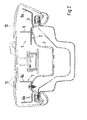
- the deformation element 1; 1a comprises a plurality of U-profiles 2 or U-shaped elements with a web 3 and limbs S1, S2 delimiting them.
- the profiles 2 are connected to one another via a longitudinal connecting web 4 and / or 5 to form a structural unit.
- One or more stiffening webs 6, 6a can be arranged between the legs S1, S2 of the profiles 2. These stiffening webs 6, 6a are either provided at the end of the profile 2 as stiffening webs 6a or as stiffening webs 6 in a region between the two legs of the profile 2.
- the U-profiles 2 are connected by means of the connecting webs 4, 5, one or two or several connecting bars can be used.
- the connecting webs 4, 5 are arranged adjacent to each other.
- the deformation element 1 in the vehicle pillar consists essentially of two so-called strands A and B, which form a U, the upper end of the Deformation elements 1 can consist of a continuous U-profile 10.
- the Strands A and B are each on a shelf 11, 12 of a support profile of the column 7 arranged and connected to these.
- the webs 3 of the profile are the stops 11, 12 trimmed and are supported on this.
- the legs S1, S2 are against it spaced from an inner lining 13, as shown in Fig. 2 in more detail.
- the Legs S1 and S2 can have different heights, which of the Installation conditions. Due to the attachment of the U-profiles 2 with the Carrier profile of the column 7 are the webs 3 of the profiles 2 approximately in a common plane arranged.
- the U-profiles 2 can have a different length I, I1 exhibit.
- the stiffening webs 6 can vary in location in the profile 2 be arranged, d. H. they are not arranged in a common plane. That's how they are Stiffening webs 6a, for example, provided at the end of the profile 2 and form with the U-profile is an open box-shaped element.
- the connecting webs 4, 5 between the profiles 2 can also be used, for example be staggered from profile to profile. In the drawings they are Connecting webs 4, 5 each aligned on a line.
- the upper end of the Deformation elements 1 formed by a ramp part 15 with an inclined surface 15a his.
- the inclined surface 15a of the ramp part 15 gives a direction for a head airbag so that they are guided into an optimized position towards the head of an occupant can.
- This ramp part 1a is an integral part of the deformation element 1 and also serves to absorb energy in the event of a head impact.
- the deformation element 1a according to FIGS. 7 and 8 is also in the roof area of the Arranged vehicle, the structure of the deformation element 1 for the column 7th equivalent.
- the profiles 2 are fastened with their webs 3 to the rigid headlining 16, the legs S1 and S2 facing the carrier 17 of the vehicle body.
- the carrier 17 represents a roof cross member, the end with vehicle pillars connected is.
- the deformation element 1 a extends with a first region 18 across the entire width of the roof. A second angled to these Area 19 extends in the vehicle longitudinal direction.
- the deformation element is 1a arranged between the rigid headliner 16 and the carrier 17, the Canopy 16 can be connected to the support structure via clips 19 or the like.
Landscapes
- Engineering & Computer Science (AREA)
- Mechanical Engineering (AREA)
- Chemical & Material Sciences (AREA)
- Combustion & Propulsion (AREA)
- Transportation (AREA)
- Body Structure For Vehicles (AREA)
- Vehicle Interior And Exterior Ornaments, Soundproofing, And Insulation (AREA)
Abstract
Description
Es zeigen
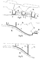
- Fig. 1
- eine schaubildliche Darstellung eines Deformationselements mit Rampenteil für einen Kopfairbag,
- Fig. 2
- einen Horizontalschnitt durch das Deformationselement nach der Linie II-II der Fig. 1,
- Fig. 3
- einen Vertikalschnitt durch das Deformationselement nach der Linie III-III der Fig. 1,
- Fig. 4
- einen Vertikalschnitt durch das Deformationselement nach der Linie IV-IV der Fig. 1,
- Fig. 5
- einen Vertikalschnitt durch das Deformationselement nach der Linie V-V der Fig. 1,
- Fig. 6
- eine schaubildliche Darstellung des an einer Säule angeordneten Deformationselements mit Rampenteil,
- Fig. 7
- eine schaubildliche Darstellung des Deformationselements zwischen Fahrzeughimmel und Querträger der Aufbaustruktur,
- Fig. 8
- das Deformationselement nach Fig. 7 in schaubildlicher Darstellung,
- Fig. 9
- einen Vertikalschnitt durch das Deformationselement nach der Linie IX-IX der Fig. 8,
- Fig. 10
- einen Vertikalschnitt durch das Deformationselement nach der Linie X-X der Fig. 8 und
- Fig. 11
- einen Vertikalschnitt durch das Deformationselement nach der Linie XI-XI der Fig. 8.
U-profilförmigen Elementen mit einem Steg 3 und diesen begrenzende Schenkel S1, S2. Die Profile 2 sind über längsgerichtete Verbindungsstege 4 und/oder 5 miteinander zu einer Baueinheit verbunden. Zwischen den Schenkeln S1, S2 der Profile 2 können ein oder mehrere Versteifungsstege 6, 6a angeordnet sein. Diese Versteifungsstege 6, 6a sind entweder endseitig des Profils 2 als Versteifungsstege 6a oder als Versteifungsstege 6 in einem Bereich zwischen den beiden Schenkeln des Profils 2 vorgesehen.
Claims (15)
- Energieabsorbierendes Deformationselement in Säulen, Trägern und dergleichen für Kraftfahrzeuge, das in einer Aufbaustruktur zwischen einem Rohbauelement und einer Innenraumverkleidung angeordnet ist und aus einem gitterartigen Element besteht, dadurch gekennzeichnet, daß das Deformationselement (1; 1a) aus beabstandet zueinander angeordneten U-Profilen (2) mit einem Steg (3) und zwischen Schenkeln (S1, S2) der Profile (2) quergerichtet angeordneten Versteifungsstegen (6, 6a) besteht und die Profile (2) über Verbindungsstege (4, 5) zu einer langgestreckten, zumindestens in einer Ebene angeordneten Baueinheit verbunden sind.
- Deformationselement nach Anspruch 1, dadurch gekennzeichnet, daß die Stege (3) der U-Profile (2) bei Verbindung mit der Fahrzeugsäule (7) dem Rohbauelement zugerichtet sind, wobei die Schenkel (S1, S2) der Innenraumverkleidung (13) gegenüberstehen.
- Deformationselement nach Anspruch 1, dadurch gekennzeichnet, daß die Stege (3) der U-Profile (2) mit einem starren Fahrzeughimmel (16) verbunden und die Schenkel (S1, S2) einem Träger (17) zugerichtet sind.
- Deformationselement nach den Ansprüchen 1, 2 oder 3, dadurch gekennzeichnet, daß die Schenkel (S1, S2) der U-Profile (2) in Längsrichtung der Profile (2) gesehen eine unterschiedliche Höhe aufweisen.
- Deformationselement nach den Ansprüchen 1 oder 4, dadurch gekennzeichnet, daß die Höhen der Schenkel (S1, S2) der Profile (2) dem Formverlauf des Rohbauelements folgend ausgeführt sind und die Außenflächen der Profilstege (3) eine stetig fortlaufende unterbrochene Fläche bilden.
- Deformationselement nach einem oder mehreren der vorhergehenden Ansprüche, dadurch gekennzeichnet, daß die Schenkel (S1, S2) der U-Profil (2) divergierend ausgeführt sind.
- Deformationselement nach einem oder mehreren der vorhergehenden Ansprüche, dadurch gekennzeichnet, daß benachbarte U-Profile (2) mindestens zwei Verbindungsstege (4, 5) aufweisen, zwischen denen mindestens ein Versteifungssteg (6, 6a) innerhalb des Profils vorgesehen ist.
- Deformationselement nach einem oder mehreren der vorhergehenden Ansprüche, dadurch gekennzeichnet, daß das Element (1a) mit dem starren Fahrzeughimmel (16) verbunden ist und sich mit einem Mittenteil (Bereich 18) quer zum Fahrzeug sowie mit einem weiteren abgewinkelten seitelichen Teil (Bereich 19) in Längsrichtung des Fahrzeugs erstreckt.
- Deformationselement nach den Ansprüchen 1 oder 8, dadurch gekennzeichnet, daß das Element (1a) mit samt dem starren Fahrzeughimmel (16) über Halteclipse (19) am Fahrzeugrohbau befestigbar ist.
- Deformationselement nach einem oder mehreren der vorhergehenden Ansprüche, dadurch gekennzeichnet, daß das Element (1) an der Fahrzeugsäule (7) angeordnet ist und über mindestens einen Steg (3), welcher der Innenfläche der Säule (7) zugerichtet ist, verbunden wird, wobei die Innenverkleidung (13) der Säule (7) den Schenkeln (S1, S2) des Profils (2) gegenüberstehen.
- Deformationselement nach einem oder mehreren der vorhergehenden Ansprüche, dadurch gekennzeichnet, daß die Stirnkanten der Profilschenkel (S1, S2) mit einem Abstand zur Innenverkleidung (13) der Fahrzeugsäule (7) angeordnet sind.
- Deformationselement nach Anspruch 1, dadurch gekennzeichnet, daß die U-Profile (2) in Einbaulage quergerichtet zur Fahrzeugsäule (7) angeordnet und die Verbindungsstege (4, 5) längsverlaufend ausgeführt sind.
- Deformationselement nach Anspruch 1, dadurch gekennzeichnet, daß am oberen freien Ende des Deformationselements (1) ein längliches einteiliges U-förmiges Profil (15) als Deformationselement angeordnet ist, das eine unter einem Winkel schräg zum Innenraum des Fahrzeugs ausgerichtetes Rampenteil (15) mit einer Schrägfläche (15a) für einen Kopfairbag (20) aufweist, der im seitlichen Dachrahmen (30) angeordnet ist.
- Deformationselement nach einem oder mehreren der vorhergehenden Ansprüche, dadurch gekennzeichnet, daß die Versteifungsstege (6a) endseitig der Profile (2) zwischen den Schenkeln (S1, S2) angeordnet sind und sich ein offenes kastenförmiges Element ausbildet.
- Deformationselement nach einem oder mehreren der vorhergehenden Ansprüche, dadurch gekennzeichnet, daß die U-Profile (2) in Einbaulage quer zur Fahrzeugsäule (7) übereinander annähernd in einer Ebene liegend angeordnet sind und die Profile (2) zwei zueinander beabstandete Stränge (A, B) nach Art eines U bilden, die mindestens über ein durchgehendes Profilelement (10) am oberen freien Ende (21) miteinander verbunden sind.
Applications Claiming Priority (2)
| Application Number | Priority Date | Filing Date | Title |
|---|---|---|---|
| DE10063339A DE10063339C1 (de) | 2000-12-19 | 2000-12-19 | Energieabsorbierendes Deformationselement |
| DE10063339 | 2000-12-19 |
Publications (3)
| Publication Number | Publication Date |
|---|---|
| EP1216891A2 true EP1216891A2 (de) | 2002-06-26 |
| EP1216891A3 EP1216891A3 (de) | 2004-02-04 |
| EP1216891B1 EP1216891B1 (de) | 2005-04-20 |
Family
ID=7667818
Family Applications (1)
| Application Number | Title | Priority Date | Filing Date |
|---|---|---|---|
| EP01125472A Expired - Lifetime EP1216891B1 (de) | 2000-12-19 | 2001-11-06 | Energieabsorbierendes Deformationselement |
Country Status (6)
| Country | Link |
|---|---|
| US (1) | US6616219B2 (de) |
| EP (1) | EP1216891B1 (de) |
| JP (1) | JP3592669B2 (de) |
| AT (1) | ATE293550T1 (de) |
| DE (1) | DE10063339C1 (de) |
| ES (1) | ES2237521T3 (de) |
Cited By (1)
| Publication number | Priority date | Publication date | Assignee | Title |
|---|---|---|---|---|
| DE102005051926A1 (de) * | 2005-10-29 | 2006-10-19 | Audi Ag | Deformationselement |
Families Citing this family (9)
| Publication number | Priority date | Publication date | Assignee | Title |
|---|---|---|---|---|
| DE10149244A1 (de) * | 2001-10-05 | 2003-04-24 | Daimler Chrysler Ag | Tragelement für Fahrzeugkarosserie |
| DE102004058249B4 (de) | 2004-12-03 | 2021-11-04 | Volkswagen Ag | Sicherheitseinrichtung für ein Fahrzeug, insbesondere für ein Kraftfahrzeug |
| US7513566B2 (en) | 2006-02-06 | 2009-04-07 | Toyota Motor Engineering & Manufacturing North America, Inc. | Headliner stiffener with energy absorbing mechanism |
| DE102006021883A1 (de) * | 2006-05-11 | 2007-11-22 | GM Global Technology Operations, Inc., Detroit | Verstärkungsmodul für eine Kraftfahrzeugkarosserie |
| JP4227153B2 (ja) * | 2006-06-20 | 2009-02-18 | 小島プレス工業株式会社 | 車両用衝撃吸収構造体 |
| DE102007019700A1 (de) | 2007-04-26 | 2008-10-30 | Dr. Ing. H.C. F. Porsche Aktiengesellschaft | Energieabsorbierendes Deformationselement für ein Fahrzeug |
| DE102007027324B4 (de) | 2007-06-14 | 2024-10-10 | Dr. Ing. H.C. F. Porsche Aktiengesellschaft | Fahrzeugaufbau |
| DE102008053769A1 (de) | 2008-10-22 | 2010-04-29 | Dr.Ing.H.C.F.Porsche Aktiengesellschaft | Deformationselement zur Anpralldämpfung in einem Kraftfahrzeug |
| CN106143386B (zh) * | 2015-03-30 | 2020-02-04 | 天津博信汽车零部件有限公司 | 车内顶棚吸能结构、车辆顶棚以及车辆 |
Citations (1)
| Publication number | Priority date | Publication date | Assignee | Title |
|---|---|---|---|---|
| DE19505935A1 (de) | 1994-02-22 | 1995-08-24 | Toyota Motor Co Ltd | Struktur zur Absorption von Aufprallenergie durch ein nichtmetallisches Innenraummaterial eines Kraftfahrzeuges |
Family Cites Families (25)
| Publication number | Priority date | Publication date | Assignee | Title |
|---|---|---|---|---|
| US4890877A (en) * | 1988-07-12 | 1990-01-02 | General Motors Corporation | Energy absorption system for vehicle door and method of making |
| FR2694528B1 (fr) * | 1992-08-06 | 1994-09-23 | Plastic Omnium Cie | Pare-chocs à absorbeur de chocs modulaire, notamment pour véhicule automobile. |
| EP0776792B1 (de) * | 1994-08-25 | 2002-05-15 | Mitsubishi Jidosha Kogyo Kabushiki Kaisha | Aufprallenergieabsorbierende struktur für einen fahrzeuginnenraum |
| JP3000898B2 (ja) * | 1995-07-12 | 2000-01-17 | トヨタ自動車株式会社 | 自動車の衝撃エネルギ吸収構造 |
| US5709407A (en) * | 1995-10-13 | 1998-01-20 | Chrysler Corporation | Energy absorbing vehicle trim molding |
| JP3160197B2 (ja) * | 1995-12-27 | 2001-04-23 | 本田技研工業株式会社 | 車両用内装材 |
| US6059342A (en) * | 1996-02-19 | 2000-05-09 | Nissan Motor Co., Ltd. | Car body structure |
| US5700028A (en) * | 1996-03-19 | 1997-12-23 | General Motors Corporation | Air bag module with energy absorbing mounting bracket |
| CA2202226C (en) * | 1996-04-10 | 2000-01-04 | Yoshinori Noritake | Impact energy absorbing structure of vehicle upper portion of automobile |
| US5779271A (en) * | 1996-06-17 | 1998-07-14 | Chrysler Corporation | Energy absorption device for impacts imparted to a support bar of a vehicle |
| US5795013A (en) * | 1996-06-20 | 1998-08-18 | Honda Giken Kogyo Kabushiki Kaisha | Energy absorbing trim, and methods of constructing and utilizing same |
| JP3129408B2 (ja) * | 1996-11-07 | 2001-01-29 | トヨタ自動車株式会社 | 自動車用乗員保護装置の配設構造 |
| US5938273A (en) * | 1997-07-08 | 1999-08-17 | Chrysler Corporation | Vehicle energy absorption |
| JPH11129839A (ja) * | 1997-10-30 | 1999-05-18 | Kanegafuchi Chem Ind Co Ltd | 車両用ピラーカバー |
| US6082792A (en) * | 1998-05-07 | 2000-07-04 | General Electric Company | Vehicle bumper |
| US6145908A (en) * | 1998-05-11 | 2000-11-14 | Ford Global Technologies, Inc. | Energy absorbing continuously compliant swept arch for interior trim |
| US6049952A (en) * | 1998-09-10 | 2000-04-18 | Chrysler Corporation | Energy absorbing trim component fastening system |
| US6199907B1 (en) * | 1998-11-17 | 2001-03-13 | Chrysler Corporation | Method and apparatus for absorbing impact energy |
| JP2000302783A (ja) * | 1999-04-22 | 2000-10-31 | Fuji Photo Film Co Ltd | ピロロピリミジンオン化合物及びそれを用いた感熱記録材料 |
| JP2001047954A (ja) * | 1999-08-09 | 2001-02-20 | Kanegafuchi Chem Ind Co Ltd | 車両用内装材 |
| US6390538B1 (en) * | 1999-11-12 | 2002-05-21 | Kaneka Corporation | Impact absorbing member for vehicle interior |
| DE10011908C1 (de) * | 2000-03-11 | 2001-03-15 | Porsche Ag | Vorrichtung für einen Gurthöhenversteller eines Sicherheitsgurtsystems |
| US6454305B1 (en) * | 2000-12-22 | 2002-09-24 | Daimlerchrysler Corporation | Trim panel assembly for a motor vehicle |
| US6409256B1 (en) * | 2001-01-23 | 2002-06-25 | Guardian Industries Corp. | Multi-piece applique for vehicle B-pillar |
| US6474724B2 (en) * | 2001-03-26 | 2002-11-05 | Daimlerchrysler Corporation | Vehicle pillar having an interior protuberance at the roof headliner |
-
2000
- 2000-12-19 DE DE10063339A patent/DE10063339C1/de not_active Expired - Fee Related
-
2001
- 2001-11-06 ES ES01125472T patent/ES2237521T3/es not_active Expired - Lifetime
- 2001-11-06 AT AT01125472T patent/ATE293550T1/de not_active IP Right Cessation
- 2001-11-06 EP EP01125472A patent/EP1216891B1/de not_active Expired - Lifetime
- 2001-12-17 JP JP2001383502A patent/JP3592669B2/ja not_active Expired - Fee Related
- 2001-12-19 US US10/020,935 patent/US6616219B2/en not_active Expired - Lifetime
Patent Citations (1)
| Publication number | Priority date | Publication date | Assignee | Title |
|---|---|---|---|---|
| DE19505935A1 (de) | 1994-02-22 | 1995-08-24 | Toyota Motor Co Ltd | Struktur zur Absorption von Aufprallenergie durch ein nichtmetallisches Innenraummaterial eines Kraftfahrzeuges |
Cited By (1)
| Publication number | Priority date | Publication date | Assignee | Title |
|---|---|---|---|---|
| DE102005051926A1 (de) * | 2005-10-29 | 2006-10-19 | Audi Ag | Deformationselement |
Also Published As
| Publication number | Publication date |
|---|---|
| ES2237521T3 (es) | 2005-08-01 |
| EP1216891B1 (de) | 2005-04-20 |
| EP1216891A3 (de) | 2004-02-04 |
| US6616219B2 (en) | 2003-09-09 |
| JP3592669B2 (ja) | 2004-11-24 |
| JP2002249000A (ja) | 2002-09-03 |
| US20020074828A1 (en) | 2002-06-20 |
| DE10063339C1 (de) | 2001-12-06 |
| ATE293550T1 (de) | 2005-05-15 |
Similar Documents
| Publication | Publication Date | Title |
|---|---|---|
| EP1036715B1 (de) | Stossfängeranordnung | |
| DE102009012057B4 (de) | Vorrichtung zum Aufnehmen von Seitenkräften und Kraftfahrzeug mit einer derartigen Vorrichtung | |
| EP1373053A1 (de) | Vorrichtung zur verstärkung eines hohlteils eines fahrzeugs | |
| EP0426648B1 (de) | Fahrzeugtür für Personenkraftwagen | |
| EP1612127B1 (de) | Kraftfahrzeug mit einem Kofferraum | |
| DE4326270A1 (de) | Kraftfahrzeug mit einer steifen Bodenstruktur | |
| DE2715986A1 (de) | Flexible blende an stossfaengern fuer kraftfahrzeuge | |
| EP1912851B1 (de) | Kraftfahrzeug mit einer eine bodenstruktur aufweisenden karosserie, und wenigstens einem versteifungselement zum versteifen der bodenstruktur | |
| DE10063339C1 (de) | Energieabsorbierendes Deformationselement | |
| DE102004007571B4 (de) | Vorderwagen für ein Fahrzeug, insbesondere für ein Kraftfahrzeug | |
| EP1036688A2 (de) | Kraftfahrzeug, insbesondere Personenkraftwagen | |
| DE4209826A1 (de) | Stoßfänger für Fahrzeuge, insbesondere für Personenkraftwagen | |
| DE4444894C2 (de) | Überrollbügel für ein Kraftfahrzeug | |
| DE19710894A1 (de) | Wandstruktur | |
| DE10302756B4 (de) | Tragstruktur für eine Kraftwagenkarosserie | |
| DE10221583B4 (de) | Fahrzeug-Karosserieteil | |
| DE102008036177B4 (de) | Bodenstruktur für ein Kraftfahrzeug | |
| EP1422099B1 (de) | Aufbau für ein Kraftfahrzeug | |
| DE19538457A1 (de) | Mehrkammerprofil | |
| DE10031901B4 (de) | Kraftwagen mit einer zumindest bereichsweise beplankten Tragstruktur | |
| EP1231130A1 (de) | Mittelsäule einer Kraftfahrzeugkarosserie | |
| DE102004003193B4 (de) | Fahrerhaus für ein Nutzfahrzeug | |
| DE102010054688A1 (de) | Bodenstruktur für ein Kraftfahrzeug, Fahrzeugkarosserie und Kraftfahrzeug | |
| DE4326269C1 (de) | Kraftfahrzeug mit einer zwei Längsträger in einem Vorbaubereich aufweisenden Tragstruktur | |
| EP1777145B1 (de) | Windschutzscheibenanordnung |
Legal Events
| Date | Code | Title | Description |
|---|---|---|---|
| PUAI | Public reference made under article 153(3) epc to a published international application that has entered the european phase |
Free format text: ORIGINAL CODE: 0009012 |
|
| AK | Designated contracting states |
Kind code of ref document: A2 Designated state(s): AT BE CH CY DE DK ES FI FR GB GR IE IT LI LU MC NL PT SE TR |
|
| AX | Request for extension of the european patent |
Free format text: AL;LT;LV;MK;RO;SI |
|
| PUAL | Search report despatched |
Free format text: ORIGINAL CODE: 0009013 |
|
| AK | Designated contracting states |
Kind code of ref document: A3 Designated state(s): AT BE CH CY DE DK ES FI FR GB GR IE IT LI LU MC NL PT SE TR |
|
| AX | Request for extension of the european patent |
Extension state: AL LT LV MK RO SI |
|
| GRAP | Despatch of communication of intention to grant a patent |
Free format text: ORIGINAL CODE: EPIDOSNIGR1 |
|
| 17P | Request for examination filed |
Effective date: 20040804 |
|
| AKX | Designation fees paid |
Designated state(s): AT ES FR GB IT SE |
|
| REG | Reference to a national code |
Ref country code: DE Ref legal event code: 8566 |
|
| GRAS | Grant fee paid |
Free format text: ORIGINAL CODE: EPIDOSNIGR3 |
|
| GRAA | (expected) grant |
Free format text: ORIGINAL CODE: 0009210 |
|
| AK | Designated contracting states |
Kind code of ref document: B1 Designated state(s): AT ES FR GB IT SE |
|
| REG | Reference to a national code |
Ref country code: GB Ref legal event code: FG4D Free format text: NOT ENGLISH |
|
| REG | Reference to a national code |
Ref country code: IE Ref legal event code: FG4D Free format text: LANGUAGE OF EP DOCUMENT: GERMAN |
|
| REG | Reference to a national code |
Ref country code: SE Ref legal event code: TRGR |
|
| REG | Reference to a national code |
Ref country code: ES Ref legal event code: FG2A Ref document number: 2237521 Country of ref document: ES Kind code of ref document: T3 |
|
| GBT | Gb: translation of ep patent filed (gb section 77(6)(a)/1977) |
Effective date: 20050902 |
|
| PLBE | No opposition filed within time limit |
Free format text: ORIGINAL CODE: 0009261 |
|
| STAA | Information on the status of an ep patent application or granted ep patent |
Free format text: STATUS: NO OPPOSITION FILED WITHIN TIME LIMIT |
|
| ET | Fr: translation filed | ||
| 26N | No opposition filed |
Effective date: 20060123 |
|
| PGFP | Annual fee paid to national office [announced via postgrant information from national office to epo] |
Ref country code: ES Payment date: 20071129 Year of fee payment: 7 |
|
| PGFP | Annual fee paid to national office [announced via postgrant information from national office to epo] |
Ref country code: AT Payment date: 20071116 Year of fee payment: 7 |
|
| PGFP | Annual fee paid to national office [announced via postgrant information from national office to epo] |
Ref country code: SE Payment date: 20071114 Year of fee payment: 7 |
|
| REG | Reference to a national code |
Ref country code: FR Ref legal event code: TP |
|
| EUG | Se: european patent has lapsed | ||
| PG25 | Lapsed in a contracting state [announced via postgrant information from national office to epo] |
Ref country code: AT Free format text: LAPSE BECAUSE OF NON-PAYMENT OF DUE FEES Effective date: 20081106 |
|
| REG | Reference to a national code |
Ref country code: FR Ref legal event code: CD |
|
| REG | Reference to a national code |
Ref country code: ES Ref legal event code: FD2A Effective date: 20081107 |
|
| PG25 | Lapsed in a contracting state [announced via postgrant information from national office to epo] |
Ref country code: ES Free format text: LAPSE BECAUSE OF NON-PAYMENT OF DUE FEES Effective date: 20081107 |
|
| PG25 | Lapsed in a contracting state [announced via postgrant information from national office to epo] |
Ref country code: SE Free format text: LAPSE BECAUSE OF NON-PAYMENT OF DUE FEES Effective date: 20081107 |
|
| PGFP | Annual fee paid to national office [announced via postgrant information from national office to epo] |
Ref country code: FR Payment date: 20101130 Year of fee payment: 10 |
|
| REG | Reference to a national code |
Ref country code: FR Ref legal event code: TP |
|
| PGFP | Annual fee paid to national office [announced via postgrant information from national office to epo] |
Ref country code: GB Payment date: 20101118 Year of fee payment: 10 Ref country code: IT Payment date: 20101123 Year of fee payment: 10 |
|
| REG | Reference to a national code |
Ref country code: GB Ref legal event code: 732E Free format text: REGISTERED BETWEEN 20110310 AND 20110316 |
|
| REG | Reference to a national code |
Ref country code: GB Ref legal event code: 732E Free format text: REGISTERED BETWEEN 20110331 AND 20110406 |
|
| GBPC | Gb: european patent ceased through non-payment of renewal fee |
Effective date: 20111106 |
|
| REG | Reference to a national code |
Ref country code: FR Ref legal event code: ST Effective date: 20120731 |
|
| PG25 | Lapsed in a contracting state [announced via postgrant information from national office to epo] |
Ref country code: IT Free format text: LAPSE BECAUSE OF NON-PAYMENT OF DUE FEES Effective date: 20111106 |
|
| PG25 | Lapsed in a contracting state [announced via postgrant information from national office to epo] |
Ref country code: GB Free format text: LAPSE BECAUSE OF NON-PAYMENT OF DUE FEES Effective date: 20111106 |
|
| PG25 | Lapsed in a contracting state [announced via postgrant information from national office to epo] |
Ref country code: FR Free format text: LAPSE BECAUSE OF NON-PAYMENT OF DUE FEES Effective date: 20111130 |