EP1216652B1 - Telemetric medical system - Google Patents
Telemetric medical system Download PDFInfo
- Publication number
- EP1216652B1 EP1216652B1 EP01310517A EP01310517A EP1216652B1 EP 1216652 B1 EP1216652 B1 EP 1216652B1 EP 01310517 A EP01310517 A EP 01310517A EP 01310517 A EP01310517 A EP 01310517A EP 1216652 B1 EP1216652 B1 EP 1216652B1
- Authority
- EP
- European Patent Office
- Prior art keywords
- sensor
- signal
- charging device
- membrane
- housing
- Prior art date
- Legal status (The legal status is an assumption and is not a legal conclusion. Google has not performed a legal analysis and makes no representation as to the accuracy of the status listed.)
- Expired - Lifetime
Links
- 239000012528 membrane Substances 0.000 claims abstract description 44
- 238000012545 processing Methods 0.000 claims abstract description 14
- 230000004044 response Effects 0.000 claims abstract description 6
- 238000002513 implantation Methods 0.000 claims abstract description 5
- 238000004891 communication Methods 0.000 claims abstract description 4
- 230000003213 activating effect Effects 0.000 claims description 2
- 210000001519 tissue Anatomy 0.000 description 26
- 210000002216 heart Anatomy 0.000 description 18
- 238000000034 method Methods 0.000 description 18
- 238000004873 anchoring Methods 0.000 description 13
- 210000000056 organ Anatomy 0.000 description 11
- 206010019280 Heart failures Diseases 0.000 description 8
- 239000008280 blood Substances 0.000 description 8
- 210000004369 blood Anatomy 0.000 description 8
- 206010007559 Cardiac failure congestive Diseases 0.000 description 7
- 210000005246 left atrium Anatomy 0.000 description 7
- 239000003990 capacitor Substances 0.000 description 6
- 230000033001 locomotion Effects 0.000 description 6
- 239000000523 sample Substances 0.000 description 6
- 238000013459 approach Methods 0.000 description 5
- 230000036772 blood pressure Effects 0.000 description 5
- 238000012544 monitoring process Methods 0.000 description 5
- 210000003492 pulmonary vein Anatomy 0.000 description 5
- 230000008859 change Effects 0.000 description 4
- 230000010354 integration Effects 0.000 description 4
- 239000000463 material Substances 0.000 description 4
- 210000004165 myocardium Anatomy 0.000 description 4
- 210000005245 right atrium Anatomy 0.000 description 4
- 230000005540 biological transmission Effects 0.000 description 3
- 238000006243 chemical reaction Methods 0.000 description 3
- 238000010586 diagram Methods 0.000 description 3
- 230000000004 hemodynamic effect Effects 0.000 description 3
- 238000003384 imaging method Methods 0.000 description 3
- 239000007943 implant Substances 0.000 description 3
- 238000005259 measurement Methods 0.000 description 3
- 230000000241 respiratory effect Effects 0.000 description 3
- 206010013975 Dyspnoeas Diseases 0.000 description 2
- HTTJABKRGRZYRN-UHFFFAOYSA-N Heparin Chemical compound OC1C(NC(=O)C)C(O)OC(COS(O)(=O)=O)C1OC1C(OS(O)(=O)=O)C(O)C(OC2C(C(OS(O)(=O)=O)C(OC3C(C(O)C(O)C(O3)C(O)=O)OS(O)(=O)=O)C(CO)O2)NS(O)(=O)=O)C(C(O)=O)O1 HTTJABKRGRZYRN-UHFFFAOYSA-N 0.000 description 2
- 208000035478 Interatrial communication Diseases 0.000 description 2
- 206010030113 Oedema Diseases 0.000 description 2
- BQCADISMDOOEFD-UHFFFAOYSA-N Silver Chemical compound [Ag] BQCADISMDOOEFD-UHFFFAOYSA-N 0.000 description 2
- 230000002159 abnormal effect Effects 0.000 description 2
- 210000003484 anatomy Anatomy 0.000 description 2
- 239000003146 anticoagulant agent Substances 0.000 description 2
- 206010003119 arrhythmia Diseases 0.000 description 2
- QVGXLLKOCUKJST-UHFFFAOYSA-N atomic oxygen Chemical compound [O] QVGXLLKOCUKJST-UHFFFAOYSA-N 0.000 description 2
- 208000013914 atrial heart septal defect Diseases 0.000 description 2
- 206010003664 atrial septal defect Diseases 0.000 description 2
- 210000001124 body fluid Anatomy 0.000 description 2
- 239000010839 body fluid Substances 0.000 description 2
- 230000008878 coupling Effects 0.000 description 2
- 238000010168 coupling process Methods 0.000 description 2
- 238000005859 coupling reaction Methods 0.000 description 2
- 210000003238 esophagus Anatomy 0.000 description 2
- 230000006870 function Effects 0.000 description 2
- 230000004217 heart function Effects 0.000 description 2
- 229960002897 heparin Drugs 0.000 description 2
- 229920000669 heparin Polymers 0.000 description 2
- 208000010125 myocardial infarction Diseases 0.000 description 2
- 229910001000 nickel titanium Inorganic materials 0.000 description 2
- 229910052760 oxygen Inorganic materials 0.000 description 2
- 239000001301 oxygen Substances 0.000 description 2
- BASFCYQUMIYNBI-UHFFFAOYSA-N platinum Chemical compound [Pt] BASFCYQUMIYNBI-UHFFFAOYSA-N 0.000 description 2
- 229910021420 polycrystalline silicon Inorganic materials 0.000 description 2
- 229920005591 polysilicon Polymers 0.000 description 2
- 229910052709 silver Inorganic materials 0.000 description 2
- 239000004332 silver Substances 0.000 description 2
- 239000007787 solid Substances 0.000 description 2
- 230000001360 synchronised effect Effects 0.000 description 2
- XLYOFNOQVPJJNP-UHFFFAOYSA-N water Substances O XLYOFNOQVPJJNP-UHFFFAOYSA-N 0.000 description 2
- 229910000838 Al alloy Inorganic materials 0.000 description 1
- BSYNRYMUTXBXSQ-UHFFFAOYSA-N Aspirin Chemical compound CC(=O)OC1=CC=CC=C1C(O)=O BSYNRYMUTXBXSQ-UHFFFAOYSA-N 0.000 description 1
- 208000031229 Cardiomyopathies Diseases 0.000 description 1
- 206010053567 Coagulopathies Diseases 0.000 description 1
- 208000002330 Congenital Heart Defects Diseases 0.000 description 1
- 208000000059 Dyspnea Diseases 0.000 description 1
- 206010020772 Hypertension Diseases 0.000 description 1
- DGAQECJNVWCQMB-PUAWFVPOSA-M Ilexoside XXIX Chemical compound C[C@@H]1CC[C@@]2(CC[C@@]3(C(=CC[C@H]4[C@]3(CC[C@@H]5[C@@]4(CC[C@@H](C5(C)C)OS(=O)(=O)[O-])C)C)[C@@H]2[C@]1(C)O)C)C(=O)O[C@H]6[C@@H]([C@H]([C@@H]([C@H](O6)CO)O)O)O.[Na+] DGAQECJNVWCQMB-PUAWFVPOSA-M 0.000 description 1
- 208000009525 Myocarditis Diseases 0.000 description 1
- 208000007536 Thrombosis Diseases 0.000 description 1
- RTAQQCXQSZGOHL-UHFFFAOYSA-N Titanium Chemical compound [Ti] RTAQQCXQSZGOHL-UHFFFAOYSA-N 0.000 description 1
- 229960001138 acetylsalicylic acid Drugs 0.000 description 1
- 230000009471 action Effects 0.000 description 1
- 210000003423 ankle Anatomy 0.000 description 1
- 229940127219 anticoagulant drug Drugs 0.000 description 1
- 210000001367 artery Anatomy 0.000 description 1
- 230000001746 atrial effect Effects 0.000 description 1
- 239000000560 biocompatible material Substances 0.000 description 1
- 230000000747 cardiac effect Effects 0.000 description 1
- 238000005253 cladding Methods 0.000 description 1
- 230000035602 clotting Effects 0.000 description 1
- 230000015271 coagulation Effects 0.000 description 1
- 238000005345 coagulation Methods 0.000 description 1
- 239000004020 conductor Substances 0.000 description 1
- 208000028831 congenital heart disease Diseases 0.000 description 1
- 208000029078 coronary artery disease Diseases 0.000 description 1
- 230000007547 defect Effects 0.000 description 1
- 238000013461 design Methods 0.000 description 1
- 238000003745 diagnosis Methods 0.000 description 1
- 238000002405 diagnostic procedure Methods 0.000 description 1
- 230000000694 effects Effects 0.000 description 1
- 229920001971 elastomer Polymers 0.000 description 1
- 230000005672 electromagnetic field Effects 0.000 description 1
- 206010014665 endocarditis Diseases 0.000 description 1
- 239000012530 fluid Substances 0.000 description 1
- 239000011521 glass Substances 0.000 description 1
- 208000019622 heart disease Diseases 0.000 description 1
- 210000003709 heart valve Anatomy 0.000 description 1
- 208000018578 heart valve disease Diseases 0.000 description 1
- 238000002847 impedance measurement Methods 0.000 description 1
- 208000015181 infectious disease Diseases 0.000 description 1
- 208000014674 injury Diseases 0.000 description 1
- 210000003734 kidney Anatomy 0.000 description 1
- 210000005240 left ventricle Anatomy 0.000 description 1
- 239000004973 liquid crystal related substance Substances 0.000 description 1
- 210000004072 lung Anatomy 0.000 description 1
- 230000007246 mechanism Effects 0.000 description 1
- 239000007769 metal material Substances 0.000 description 1
- 210000004115 mitral valve Anatomy 0.000 description 1
- HLXZNVUGXRDIFK-UHFFFAOYSA-N nickel titanium Chemical compound [Ti].[Ti].[Ti].[Ti].[Ti].[Ti].[Ti].[Ti].[Ti].[Ti].[Ti].[Ni].[Ni].[Ni].[Ni].[Ni].[Ni].[Ni].[Ni].[Ni].[Ni].[Ni].[Ni].[Ni].[Ni] HLXZNVUGXRDIFK-UHFFFAOYSA-N 0.000 description 1
- 230000001453 nonthrombogenic effect Effects 0.000 description 1
- 230000003071 parasitic effect Effects 0.000 description 1
- 229910052697 platinum Inorganic materials 0.000 description 1
- HWLDNSXPUQTBOD-UHFFFAOYSA-N platinum-iridium alloy Chemical compound [Ir].[Pt] HWLDNSXPUQTBOD-UHFFFAOYSA-N 0.000 description 1
- 229920002635 polyurethane Polymers 0.000 description 1
- 239000004814 polyurethane Substances 0.000 description 1
- 208000037920 primary disease Diseases 0.000 description 1
- 230000029058 respiratory gaseous exchange Effects 0.000 description 1
- 230000000717 retained effect Effects 0.000 description 1
- 201000003068 rheumatic fever Diseases 0.000 description 1
- 210000005241 right ventricle Anatomy 0.000 description 1
- 231100000241 scar Toxicity 0.000 description 1
- 208000013220 shortness of breath Diseases 0.000 description 1
- 230000008054 signal transmission Effects 0.000 description 1
- 238000004088 simulation Methods 0.000 description 1
- 229910052708 sodium Inorganic materials 0.000 description 1
- 239000011734 sodium Substances 0.000 description 1
- 238000002798 spectrophotometry method Methods 0.000 description 1
- 238000011272 standard treatment Methods 0.000 description 1
- 210000002784 stomach Anatomy 0.000 description 1
- 239000000758 substrate Substances 0.000 description 1
- 230000008961 swelling Effects 0.000 description 1
- 239000010936 titanium Substances 0.000 description 1
- 229910052719 titanium Inorganic materials 0.000 description 1
- 230000008733 trauma Effects 0.000 description 1
- 210000000591 tricuspid valve Anatomy 0.000 description 1
- 210000003462 vein Anatomy 0.000 description 1
- 210000001631 vena cava inferior Anatomy 0.000 description 1
Images


Classifications
-
- A—HUMAN NECESSITIES
- A61—MEDICAL OR VETERINARY SCIENCE; HYGIENE
- A61B—DIAGNOSIS; SURGERY; IDENTIFICATION
- A61B5/00—Measuring for diagnostic purposes; Identification of persons
- A61B5/68—Arrangements of detecting, measuring or recording means, e.g. sensors, in relation to patient
- A61B5/6846—Arrangements of detecting, measuring or recording means, e.g. sensors, in relation to patient specially adapted to be brought in contact with an internal body part, i.e. invasive
- A61B5/6879—Means for maintaining contact with the body
- A61B5/6882—Anchoring means
-
- A—HUMAN NECESSITIES
- A61—MEDICAL OR VETERINARY SCIENCE; HYGIENE
- A61B—DIAGNOSIS; SURGERY; IDENTIFICATION
- A61B5/00—Measuring for diagnostic purposes; Identification of persons
-
- A—HUMAN NECESSITIES
- A61—MEDICAL OR VETERINARY SCIENCE; HYGIENE
- A61B—DIAGNOSIS; SURGERY; IDENTIFICATION
- A61B5/00—Measuring for diagnostic purposes; Identification of persons
- A61B5/0002—Remote monitoring of patients using telemetry, e.g. transmission of vital signals via a communication network
- A61B5/0031—Implanted circuitry
-
- A—HUMAN NECESSITIES
- A61—MEDICAL OR VETERINARY SCIENCE; HYGIENE
- A61B—DIAGNOSIS; SURGERY; IDENTIFICATION
- A61B5/00—Measuring for diagnostic purposes; Identification of persons
- A61B5/02—Detecting, measuring or recording pulse, heart rate, blood pressure or blood flow; Combined pulse/heart-rate/blood pressure determination; Evaluating a cardiovascular condition not otherwise provided for, e.g. using combinations of techniques provided for in this group with electrocardiography or electroauscultation; Heart catheters for measuring blood pressure
- A61B5/021—Measuring pressure in heart or blood vessels
- A61B5/0215—Measuring pressure in heart or blood vessels by means inserted into the body
-
- A—HUMAN NECESSITIES
- A61—MEDICAL OR VETERINARY SCIENCE; HYGIENE
- A61B—DIAGNOSIS; SURGERY; IDENTIFICATION
- A61B5/00—Measuring for diagnostic purposes; Identification of persons
- A61B5/07—Endoradiosondes
- A61B5/076—Permanent implantations
-
- Y—GENERAL TAGGING OF NEW TECHNOLOGICAL DEVELOPMENTS; GENERAL TAGGING OF CROSS-SECTIONAL TECHNOLOGIES SPANNING OVER SEVERAL SECTIONS OF THE IPC; TECHNICAL SUBJECTS COVERED BY FORMER USPC CROSS-REFERENCE ART COLLECTIONS [XRACs] AND DIGESTS
- Y10—TECHNICAL SUBJECTS COVERED BY FORMER USPC
- Y10S—TECHNICAL SUBJECTS COVERED BY FORMER USPC CROSS-REFERENCE ART COLLECTIONS [XRACs] AND DIGESTS
- Y10S128/00—Surgery
- Y10S128/903—Radio telemetry
Definitions
- the present invention relates, in general, to telemetric medical devices. More particularly, the present invention relates to a novel telemetric medical system which is capable of various medical applications including the measurement of a parameter within a patient's body, particularly an organ.
- a novel telemetric medical system which is capable of various medical applications including the measurement of a parameter within a patient's body, particularly an organ.
- One such application of the present invention is as an implantable telemetric endocardial pressure system, its associated novel components and their novel methods of use.
- the disclosure is directed to an implantable medical sensor which determines the oxygen content of blood.
- the sensor includes a miniaturized hybrid circuit that includes light-emitting diode means, phototransistor means, and a substrate to which the light-emitting diode means and phototransistor means are bonded in a desired circuit configuration.
- the hybrid circuit is hermetically sealed within a cylindrical body made from a material that is substantially transparent to light, such as glass. Feedthrough terminals provide means for making an electrical connection with the hybrid circuit.
- the light-emitting diode means is driven with a stair-stepped current pulse.
- the senor is to sense the reflective properties of body fluid, such as blood, for spectrophotometric analysis.
- the sensor is embedded within a bilumen pacemaker lead and positioned near the distal electrode of the lead so that the sensor resides within the heart when the lead is implanted within a patient, thereby allowing the sensed oxygen content of the blood within the heart to be a physiological parameter that can be used to control the pacing interval of a rate-responsive pacemaker.
- US Patent 5,353,800 discloses an implantable pressure sensor lead having a hollow needle adapted to be screwed into a patient's heart.
- the pressure sensor is supplied electrical power through conductors in the sensor.
- a leadless implantable cardiac arrhythmia alarm which continuously assesses a patient's heart function to discriminate between normal and abnormal heart functioning and, upon detecting an abnormal condition, generates a patient-warning signal.
- the alarm is capable of sensing impedance measurements of heart, respiratory and patient motion and, from these measurements, generating an alarm signal when the measurements indicate the occurrence of a cardiac arrhythmia.
- the sensor uses an antenna system having a coil inductor for generating an electromagnetic field into tissue for detecting changes in impedance which relate to a physiological phenomena.
- the size of the inductor is preselected in order to match the dimensions of the organ or structure to be measured.
- Implantable devices that employ telemetry for transmitting or receiving data from an external device.
- One such device is, for example, the system disclosed in US Patent 6,021,352 (Christopherson et al. ).
- the device utilizes a pressure sensor as a transducer for sensing respiratory effort of the patient.
- Respiratory waveform information is received by an implantable pulse generator (IPG)/simulator from a transducer and inspiration synchronous simulation is provided by the IPG.
- IPG implantable pulse generator
- US Patent 5,999,857 discloses a telemetry system for use with implantable devices such as cardiac pacemakers and the like, for two-way telemetry between the implanted device and an external programmer.
- the system employs oscillators with encoding circuits for synchronous transmission of data symbols in which the symbols form the telemetry carrier.
- the system provides circuits for higher density data encoding of sinusoidal symbols, including combinations of BPSK, FSK, and ASK encoding.
- Embodiments of transmitters for both the implanted device and the external programmer, as well as modulator and demodulator circuits, are also disclosed. It is important to note that the implant device has its own power supply in the form of a battery for powering all of the circuitry and components of the implanted device.
- the present invention is directed to a novel telemetric medical system for use with various medical applications such as monitoring medical conditions or measuring parameters within a patient's body for different types of organs, including tissue, as well as their function.
- the present invention is a telemetric medical system comprising a telemetric medical sensor for implantation in a patient's body for measuring a parameter therein.
- the sensor comprises a housing, and a membrane at one end of the housing, wherein the membrane is deformable in response to the parameter.
- a microprocessor which is in the form of a microchip, is positioned within the housing and operatively communicates with the membrane for transmitting a signal indicative of the parameter.
- the signal transmitted by the sensor is a digital signal.
- the system further comprises a signal reading and charging device that is locatable outside of a patient's body for communication with the sensor.
- the signal reading and charging device comprises a casing and a circuit within the casing.
- the circuit comprises a logic control unit and a processing unit operatively connected to the logic control unit.
- the logic control unit is for sending a powering signal to the sensor, optionally through a sine wave driver operatively connected to the control unit, for remotely powering the sensor.
- the logic control unit optionally through a deep detector, is also for receiving the transmitted signal from the sensor.
- the processing unit is operatively connected to the logic control unit for converting the transmitted signal into the measured parameter.
- the powering signal may be a sinusoidal wave signal approximately 4-6 MHz.
- the processing unit may include a power source operatively connected to the circuit and a power switch for activating and deactivating the device.
- the signal reading and charging device may also include an antenna coil for sending the powering signal to the sensor and for receiving the transmitted digital signal from the sensor.
- the signal reading and charging device may also include a display, which may be an LCD screen, for displaying the measured parameter.
- the processing unit decodes the transmitted signal.
- the microprocessor which is in the form of a microchip, comprises an array of photoelectric cells which may be arranged in staggered rows.
- the array may also include a reference photoelectric cell located at one end of the array.
- a light emitting diode (LED) transmits light at the photoelectric cells and, where the array includes a reference photoelectric cell, at the reference photoelectric cell.
- the sensor further comprises a shutter connected to the membrane and moveable between the photoelectric cells and the LED in response to the deforming of the membrane.
- the sensor may be arranged such that the reference photoelectric cell is not blocked by the shutter and remains exposed to the light emitted by the LED.
- the microchip may further comprise a plurality of comparators operatively connected to the photoelectric cells and a buffer operatively connected to the comparators for storing and transmitting the digital signal.
- a buffer may be operatively connected to the comparators for storing and transmitting the signal.
- the sensor may further comprise an antenna, in the form of a coil, operatively connected to the microchip wherein the antenna is located at the exterior of the housing. Alternatively, the antenna may be located within the housing of the sensor.
- the present invention relates to a novel telemetric medical system 30, as schematically illustrated in FIG. 8, as well as its novel components and methods of use useful for various medical applications, as explained and demonstrated herein.
- One aspect of the system 30 of the present invention is to remotely sense and measure a characteristic or parameter (or number of various parameters including the magnitude of any parameter) within a patient's body, or within an organ or tissue of the patient's body, through the use of a novel implantable telemetric medical sensor 50, which is completely wireless, and a novel signal reading and charging device 140 which operatively communicates with the sensor 50.
- the senor 50 comprises a housing 52 made of a biocompatible material such as polysilicon or titanium.
- the housing 52 preferably has a cylindrical shape although any type of shape for the housing 52 is acceptable.
- the housing 52 has an approximate length ranging between 4 -5 mm and an approximate diameter ranging from 2.5 - 3 mm in diameter.
- the housing 52 can also be smaller, e.g. 3 mm in length and a 1-2 mm outer diameter.
- the housing 52 includes cylindrical walls that are approximately 250 ⁇ m in thickness.
- a flexible membrane 56 made of a deformable material is fixed to one end of the housing 52.
- a notch 58 and a circumferential groove 60 are provided on an exterior surface of the housing 52 for facilitating delivery and implantation of the sensor 50.
- the membrane 56 is made of a flexible or deformable material such as polysilicon rubber or polyurethane.
- the membrane 56 has an approximate thickness of 20 ⁇ m and has a diameter ranging from approximately 1.5 - 2 mm.
- the membrane 56 is normally biased outwardly from the housing 52 due to the interior pressure within the housing 52.
- the membrane 56 is forced to bulge inwardly into the housing 52 whenever the pressure exterior of the housing 52 exceeds the internal pressure within the housing 52.
- the membrane 56 Since the membrane 56 is deformable and normally biased outwardly from the housing 52, the membrane 56 responds directly to the environment of the tissue or organ being monitored and/or measured for a particular characteristic or parameter. In response to even the slightest changes in these characteristics or parameters, the membrane 56 deforms inwardly toward the interior of the housing 52. Accordingly, there is a direct relationship or correspondence between any change in measured characteristic or parameter and the amount or degree of deforming action or movement of the membrane 56.
- the membrane 56 has a relatively large area in dimension when compared to solid state membrane devices, such as piezoelectric sensors or fabricated memory chips utilizing membranes. Accordingly, the requirements from the electronics of the sensor 50 are less demanding. Additionally, the membrane 56 has a much larger deflection than that of the solid state membrane.
- the sensor 50 also includes an antenna coil 68 which is operatively connected to the internal components of the sensor 50 by an antenna lead 70.
- the antenna coil 68 is an inductance coil having a spiralled coil configuration.
- the material used for the antenna wire is approximately 90% silver content with a cladding of platinum iridium of approximately 10% content.
- the antenna coil 68 is preferably made of 20-25 turns of 30 ⁇ m thickness wire.
- the antenna outer diameter is 1.5-2.0 cm (Fig. 2).
- the antenna coil 68 possesses a very low parasitic capacitance. Additionally, the antenna coil 68, due to its silver/platinum content wire has extremely high conductivity and is extremely flexible.
- antenna 68 is described as being external of the housing 52, it is well within the scope of the invention to include any type of suitable antenna, such as an antenna that is contained within the housing 52.
- the sensor 50 further includes anchoring legs 64 resiliently biased to the exterior of the housing 52.
- the number of anchoring legs 64 can vary depending on the desired degree of anchoring and geography of the anatomy in which the sensor 50 is to be placed.
- the anchoring legs 64 are made from wire utilizing shape memory metal material, such as a nickel titanium alloy (NiTinol).
- NiTinol nickel titanium alloy
- the anchoring legs 64 have a concave configuration with a radius of curvature that curves into the tissue or organ in which the sensor 50 is to be anchored. Other appropriate configurations for the anchoring legs 64 are also contemplated herein.
- the senor 50 is coated with a nonthrombogenic or anticoagulating agent such as Heparin prior to implantation in order to prevent thrombosis, clotting, etc.
- a nonthrombogenic or anticoagulating agent such as Heparin prior to implantation in order to prevent thrombosis, clotting, etc.
- FIG. 3 illustrates an alternative embodiment of the sensor 50 having a tapered end 54 on the housing 52.
- the tapered end 54 has a tissue piercing tip 55 and helical threads 57 arranged on an outer surface of the tapered end 54 in order to facilitate the direct anchoring of the tapered end 54 of the housing 52 through direct threading into tissue.
- FIG. 4 illustrates another alternative embodiment sensor 50 including a plurality tissue barbs 59 fixed to the tapered end 54 of the housing 52.
- the barbs 59 have a tissue piercing tip curved outwardly away from the tissue piercing tip 55. Accordingly, along with the tissue piercing tip 55, the tissue barbs 59 grasp firmly into the tissue for firmly anchoring the housing 52 in the tissue.
- the interior of the housing 52 includes a microprocesser 90, in the form of a microchip, fixed within one of the interior walls of the housing 52.
- the lead 70 of the antenna coil 68 is operatively connected to the microprocessor 90.
- Microprocessor 90 includes an array 92 of photoelectric cells 95 arranged in a patterned configuration, e.g. eight staggered rows containing eight photoelectric cells 95 in each row.
- a reference photoelectric cell 97 is located at one end of the array 92 resulting in an array 92 having a total of sixty-five photoelectric cells such as illustrated in FIG. 7.
- the photoelectric cell array 92 provides for 64 degrees of resolution.
- the pitch distance between each photocell 95 is approximately 1 ⁇ 4 the size of a photocell 95.
- the reference photocell 97 has a dimension that is approximately the size of the pitch, e.g. 1 ⁇ 4 the size of a photocell 95, thus providing a resolution that is equal to a motion of 1 ⁇ 4 of the photocell.
- a light emitting diode (LED) 100 is operatively connected to the microprocessor 90 and is positioned above and spaced parallel and away from the photoelectric cell array 92.
- a shutter 62 is connected to the inner surface of the membrane 56 and extends logitudinally from the membrane 56 within housing 52.
- the shutter 62 has a substantially D-shaped configuration and logitudinally extends between the LED 100 and the photoelectric cell array 92.
- the shutter 62 is made from an aluminum alloy and is positioned such that the planar surface of the shutter 62 directly faces the photoelectric cell array 92.
- the shutter 62 is fixed to the deformable membrane 56 such that the shutter 62 moves in association with the membrane 56.
- the shutter 62 longitudinally extends over a number of photoelectric cells 95 in the array 92 in direct relation to the inward movement of the membrane 56 as it is being deformed.
- the shutter 62 moves longitudinally outwardly from the end of the housing 52 along with the membrane 56. Accordingly, the shutter 62 obscures or blocks a number of the photoelectric cells 95 in accordance with the degree of movement of the membrane 56.
- the shutter 62 when the shutter 62 is positioned over a specific number of photoelectric cells 95, light from the LED 100 is prevented from reaching the photoelectric cells 95 and affects signal transmission from these cells 95.
- This arrangement constitutes an analog-to-digital (A/D) conversion which is power effective since there is a simple counting of the number of photocells that are on or off as a measure of the shutter's motion.
- the analog-to-digital conversion Accordingly, the microprocessor 90 operatively communicates with the membrane 56.
- the reference photoelectric cell 97 is never obscured or covered by the shutter 62 since it is located at the far end (end away from the membrane 56) of the array 92.
- the shutter 62 and membrane 56 are calibrated such that even upon maximum deflection inwardly into the housing 52, it results in the reference photoelectric cell 97 being permanently exposed to the LED 100 for use as a reference signal for the sensor 50. Yet, the power dissipation of the photocell is very low.
- the microprocessor 90 is a circuit wherein the antenna coil 68 and a resonance capacitor 102 operate as a resonating oscillator for the sensor 50.
- the antenna coil 68 receives transmitted RF signals sent by the signal reading and charging device 140 as illustrated in FIGS. 8 and 9.
- the RF signal received at the antenna coil 68 is a charging signal for powering the microprocessor 90.
- the antenna coil 68 and capacitor 102 Upon receiving the RF charging signal, the antenna coil 68 and capacitor 102 resonate and charge a charge capacitor 114 through diode 116.
- the capacitor 114 powers the LED 100 and a logic circuit 91 through control unit 104.
- the LED Upon powering of the LED 100 by the charged capacitor 114, the LED emits light to the photoelectric cell array 92 which is kept at negative voltage.
- the photoelectric cell array 92 is designated P 1 , P 2 , ... P 64 and P ref , respectively.
- Each photoelectric cell 95 (P 1 -P 64 ) are connected in parallel to a plurality of comparators 120 designated C1, C2 ... C64.
- the reference photoelectric cell 97 is operatively connected to each comparator 120 (C1-C64) for providing a reference signal to each comparator 120 in comparison to the signal received from each respective photoelectric cell 95.
- the logic circuit 91 is powered and controlled by the control unit 104 and a clock 106.
- the control unit 104 is connected to each comparator 120.
- a buffer 126 having a plurality of buffer cells 129 (sixty-four total buffer cells corresponding to each comparator C1-C64) is operatively connected to the comparators 120.
- Each buffer cell 129 is a flip-flop, or memory cell, which receives a signal from its respective comparator C1-C64 resulting in a binary number which is sixty-four digits long (a series of ones or zeros). All buffer cells 129 are filled in a single clock cycle and each buffer 129 has either "0" or "1" in it. After all sixty-four buffer cells 129 have been filled with its respective binary number, the digital signal representing all sixty-four bytes is sent to the signal reading and charging device 140 by the control unit 104. After transmitting the digital signal, the control unit 104 is reset by the clock 106 awaiting further signal inputs from the signal reading and charging device 140. Encryption of the binary number is provided by the signal reading and charging device 140 described in greater detail below.
- the digital signal is transmitted from the buffer 126 and activates switch 112 resulting in a transmission of the digital signal from the antenna coil 68 to the antenna coil 162 of the signal reading and charging device 140.
- the senor 50 is both a wireless transponder and a low-powered device capable of fast update rate, despite its passive nature, due to the inherent analog-to-digital (A/D) conversion mechanism employed in the sensor 50, e.g. the photoelectric cell array 92, which directly converts the membrane 56 deflection into a digital signal, with no power consumption as would be required for a conventional electronic A/D converter.
- A/D analog-to-digital
- the signal reading and charging device 140 is for use outside of a patient's body or at the exterior surface of the patient's body.
- the signal reading and charging device 140 includes a casing 145, which is a housing, having a liquid crystal display (LCD) display screen 172 mounted in an opening in the housing 145.
- the signal reading and charging device also commonly referred to as a read/charge device, reader/charger or reader/charger device, is activated by a power switch or toggle 146 extending from the casing 145.
- Antenna coil 162 operatively communicates with the antenna coil 68 of the sensor 50 by inductance coupling.
- the logic circuit 91 transmits the digital signal from the sensor 50 through sensor antenna coil 68
- the coupling constant of the reader/charger antenna coil 162 is changed and is detected by a deep detector 168 operatively connected to the reader/charger antenna coil 162.
- the deep detector 168 is sensitized to detect a change in the amplitude of the signal for as low as a 0.01% change in amplitude.
- a read/charge logic control unit 154 is operatively connected to the deep detector 168 for determining the threshold for the deep detector 168.
- the logic control unit 154 also includes a power source 151 for powering the components of the reader/charger device 140.
- the reader/charger circuit 150 further includes a processing unit 170 operatively connected to the logic control unit 154.
- the processing unit 170 contains the algorithm for converting the digital signal received from the sensor 50 (FIG. 8) into a measured parameter for the medical parameter, condition or characteristic sensed at the implanted sensor 50. Additionally, the processing unit 170 includes encryption code for encryption of the digital signal (sixty-four bit signal) using encryption algorithms such as exclusive-OR (XOR), RSA methods (RSA Security, Inc.), etc.
- the LCD display 172 is operatively connected to the processing unit 170 for displaying the measured parameter (hemodynamic blood pressure in the example above) converted from the digital signal in real time.
- the signal reading and charging device 140 When measuring characteristics of a body fluid such as blood, the signal reading and charging device 140 maintains an active reading volume around the sensor 50, ranging anywhere from 5 - 25cm, and preferably, an active reading volume ranging approximately 10 - 15cm. Moreover, with the telemetric medical system 30, through the sensor 50, and the signal reading and charging device 140, it is possible to sample multiple readings per second. Preferably, approximately 10-20 readings per second are possible with the present invention.
- Other attributes associated with the present invention when utilized as a pressure monitor in a chamber of the heart include monitoring a pressure range of +/- 4 kPa (30 mmHg); an accuracy (at 5 mSec. integration) of +/- 0.133 kPa (1 mmHg) with a repeatability (at 5 mSec. integration) of +/- 0.133 kPa (1 mmHg). It is important to note that the pressure boundaries can be changed easily by changing the size and dimensions, such as width, of the membrane without any change to the electronics. This is important for allowing the present invention to be adapted for various applications while using the same design.
- the control unit 154 is also operatively connected to a sine-wave driver 158 for generating a sinusoidal wave signal of approximately 4 to 6 MHz.
- the sinusoidal wave signal is generated by the sine-wave driver 158 through capacitor 160 to the reader/charger antenna coil 162 for transmission or sending to the antenna coil 68 of the sensor 50 in order to power or charge the sensor 50 as described above.
- the telemetric medical system 30 is useful for nearly any type of medical diagnostic procedure where it is desireable to implant the sensor 50 at a portion of the body, particularly tissue or organ of interest.
- the telemetric medical system 30 according to the present invention allows for remote monitoring and diagnosis of a condition of the tissue or organ by being able to rapidly sample various parameters or variables of any physical condition within the patient's body at the site of interest. Since the telemetric medical system 30 is wireless, these types of procedures are conducted in a completely non-invasive manner with minimal trauma to the patient.
- CHF congestive heart failure
- the ailing heart 400 keeps functioning but not as efficiently as it should. People with CHF cannot exert themselves because they become short of breath and tired. As blood flowing out of the heart 400 slows, blood returning to the heart 400 through the veins backs up, causing congestion in the tissues. Often swelling (edema) results, most commonly in the legs and ankles, but possibly in other parts of the body as well. Sometimes fluid collects in the lungs and interferes with breathing, causing shortness of breath, especially when a person is lying down. Heart failure also affects the ability of the kidneys to dispose of sodium and water. The retained water increases the edema.
- CHF is the most common heart disease in the United States and it is estimated that over 5 million patients suffer from it.
- One of the more predictive hemodynamic parameters being measured in patients with CHF is blood pressure in the left atrium 410, e.g. left atrial (LA) pressure.
- LA left atrial
- this parameter is measured by employing invasive right heart catheterization with a special balloon catheter such as the Swan-Gantz catheter.
- a particular chamber either right atrium 415, right ventricle 419, left atrium 410 or left ventricle 420
- the telemetric medical system 30 it is desireable to measure the blood pressure in a particular chamber (either right atrium 415, right ventricle 419, left atrium 410 or left ventricle 420) in the heart 400 utilizing the telemetric medical system 30 according to the present invention.
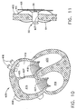
- blood pressure can be directly monitored in the left atrium 410 of the heart 400. Accordingly, it is desireable to implant the sensor 50 at fossa ovalis 407 within the septum 405.
- the fossa ovalis 407 has a pre-existing hole or opening that either remains open or patent and is normally covered by a small flap of tissue. In approximately 85% of the normal population, the fossa ovalis 407 is completely occluded, e.g. there is no hole in the septum 405.
- a transcatheter approach has been found to be particularly useful for the patient population already having the pre-existing hole at the fossa ovalis 407. Accordingly, in performing this method according to the present invention, first, a transesophageal ultrasonic probe (not shown) is inserted into the patient's mouth and placed in the esophagus. In most cases, the transesophageal ultrasonic probe is positioned approximately 30 - 35cm from the mouth, i.e. in most cases positioned just above the patient's stomach.
- a wire (not shown) is inserted into the right atrium 415 through an appropriate vessel such as the inferior vena cava 408 wherein the wire is guided through the fossa ovalis 407 by gently lifting the tissue flap away from the patent opening at the fossa ovalis 407.
- the wire is guided to one of the pulmonary veins 416 for placement of the distal end of the wire in order to properly position and anchor the wire in the opening of the pulmonary vein 416. Accordingly, the pulmonary vein 416 has been proven to be a very reliable and steady anchoring point for the wire.
- a catheter sheath (“over-the-wire” type -- not shown) is guided over the wire through the right atrium 415 and the fossa ovalis 407 and positioned within the left atrium 410, for instance, very close to the opening of the pulmonary vein 416.
- the wire is removed from the patient's heart 400 and the sensor 50 is delivered through the catheter sheath by one of the many standard catheter-based delivery devices (not shown). Accordingly, the sensor 50 can be delivered to the fossa ovalis 407 by any of the typical catheter-based delivery devices normally associated with implantable pacemakers, electrodes, atrial septal defect (ASD) occlusion devices, etc. Accordingly, the sensor 50 is deliverable with typical delivery devices such as the Amplatzer® Delivery System, manufactured by AGA Medical Corporation of Golden Valley, Minnesota.
- the sensor 50 After placement of the catheter sheath, the sensor 50 is deployed from the catheter sheath within the fossa ovalis 407 as best illustrated in Fig. 11. Upon deployment, the sensor 50 utilizes the anchoring legs 64 for anchoring the sensor 50 to the septum 405 and occluding the opening at the fossa ovalis 407.
- the sensor 50 is placed in the fossa ovalis 407 for those patients not having a pre-existing opening in the fossa ovalis 407 through means of an anterograde approach.
- a transesophageal ultrasonic probe is positioned in the patient's esophagus as described above.
- an opening is made in the septum 405 at the fossa ovalis 407 in order to place and accommodate the sensor 50.
- the opening is made with a standard needle catheter (not shown) such as the BRK TM Series Transseptal Needle manufactured by St. Jude Medical, Inc. of St. Paul, Minnesota.
- the needle catheter is initially placed in the right atrium 415 and positioned at the fossa ovalis 407.
- the tip of the needle of the needle catheter penetrates the fossa ovalis 407 and the catheter is inserted through the fossa ovalis 407 into the left atrium 410 through the newly created opening in the fossa ovalis 407 by the needle catheter.
- the sensor 50 is introduced with the delivery device, such as the delivery device described above, and placed in the fossa ovalis opening as shown in Fig. 11.
- the anchoring legs 64 Upon deployment of the anchoring legs 64, the opening in the fossa ovalis 407 is occluded around the sensor housing 52 and the sensor 50 fixed to the septum 405 in a secure fashion.
- transesophageal ultrasonic imaging is utilized for both the transcatheter and the anterograde approach as described above in accordance with each method step of the present invention. Since either method according to the present invention can be utilized with the transesophageal ultrasonic guidance, other imaging modalities such as flouroscopy can be eliminated. As such, the methods according to the present invention can be conducted in an outpatient clinic or doctor's office as a bedside procedure. By eliminating the need for a flouroscope, the method according to the present invention also eliminates the need for conducting the procedure in a catheter lab which only adds additional time and cost to the procedure and additional time and inconvenience to the patient.
- the patient is provided with standard treatment to prevent excessive coagulation or endothelialization. For instance, it is common practice to prescribe aspirin and/or an anticoagulant such as Heparin for a period of time such as six months.
- aspirin and/or an anticoagulant such as Heparin for a period of time such as six months.
- the senor 50 is fixed to the septum 405 in order to provide real time pressure monitoring in the left atrium 410. Since the sensor 50 is a wireless transponder and a battery low power receiver, the sensor 50 does not impede the natural function of the heart 400 and is truly minimally invasive.
- the signal reading and charging device 140 maintains an active reading volume around the sensor 50 ranging anywhere from 5 - 25cm, and preferably, an active reading volume ranging approximately 10 - 15cm. Moreover, with the sensor 50, and the signal reading and charging device 140, it is possible to sample multiple readings per second. Preferably, approximately 10-20 readings per second are possible with the present invention.
- Other attributes associated with the present invention when utilized as a pressure monitor in a chamber of the heart include monitoring a pressure range of plus/minus 4 kPa (30 mmHg); and accuracy (at five Mmsec. integration) of plus/minus 0.133 kPa (1 mmHg) and a repeatability (at 5msec. integration) of plus/minus 0.133 kPa (1 mmHg).
Priority Applications (1)
| Application Number | Priority Date | Filing Date | Title |
|---|---|---|---|
| CY20071101182T CY1106864T1 (el) | 2000-12-18 | 2007-09-12 | Τηλεμετρικο ιατρικο συστημα |
Applications Claiming Priority (2)
| Application Number | Priority Date | Filing Date | Title |
|---|---|---|---|
| US739571 | 2000-12-18 | ||
| US09/739,571 US6636769B2 (en) | 2000-12-18 | 2000-12-18 | Telemetric medical system and method |
Publications (3)
| Publication Number | Publication Date |
|---|---|
| EP1216652A2 EP1216652A2 (en) | 2002-06-26 |
| EP1216652A3 EP1216652A3 (en) | 2002-12-04 |
| EP1216652B1 true EP1216652B1 (en) | 2007-06-27 |
Family
ID=24972906
Family Applications (1)
| Application Number | Title | Priority Date | Filing Date |
|---|---|---|---|
| EP01310517A Expired - Lifetime EP1216652B1 (en) | 2000-12-18 | 2001-12-17 | Telemetric medical system |
Country Status (14)
| Country | Link |
|---|---|
| US (1) | US6636769B2 (es) |
| EP (1) | EP1216652B1 (es) |
| JP (1) | JP3971178B2 (es) |
| KR (1) | KR100853949B1 (es) |
| AT (1) | ATE365498T1 (es) |
| AU (1) | AU780642B2 (es) |
| CA (1) | CA2365211A1 (es) |
| CY (1) | CY1106864T1 (es) |
| DE (1) | DE60129101T2 (es) |
| DK (1) | DK1216652T3 (es) |
| ES (1) | ES2287086T3 (es) |
| HK (1) | HK1045089B (es) |
| IL (1) | IL146960A (es) |
| PT (1) | PT1216652E (es) |
Cited By (1)
| Publication number | Priority date | Publication date | Assignee | Title |
|---|---|---|---|---|
| US8255062B2 (en) | 2005-08-19 | 2012-08-28 | Pacesetter, Inc. | Left chamber pressure sensor lead delivery system |
Families Citing this family (84)
| Publication number | Priority date | Publication date | Assignee | Title |
|---|---|---|---|---|
| US20020120200A1 (en) * | 1997-10-14 | 2002-08-29 | Brian Brockway | Devices, systems and methods for endocardial pressure measurement |
| US20060064135A1 (en) * | 1997-10-14 | 2006-03-23 | Transoma Medical, Inc. | Implantable pressure sensor with pacing capability |
| US20020188207A1 (en) * | 1998-01-08 | 2002-12-12 | Jacob Richter | Anchor for sensor implanted in a bodily lumen |
| WO2002098271A2 (en) * | 2001-06-05 | 2002-12-12 | Barnev Ltd. | Birth monitoring system |
| US7047076B1 (en) | 2001-08-03 | 2006-05-16 | Cardiac Pacemakers, Inc. | Inverted-F antenna configuration for an implantable medical device |
| US6822569B1 (en) * | 2002-05-31 | 2004-11-23 | Sensormatic Electronics Corporation | Insertable electronic article surveillance label |
| US7357037B2 (en) * | 2002-07-10 | 2008-04-15 | Orthodata Technologies Llc | Strain sensing system |
| CA2491956C (en) * | 2002-07-10 | 2010-04-27 | Orthodata Technologies Llc | Strain sensing system |
| US8303511B2 (en) | 2002-09-26 | 2012-11-06 | Pacesetter, Inc. | Implantable pressure transducer system optimized for reduced thrombosis effect |
| EP1549394B1 (en) * | 2002-09-26 | 2011-12-07 | Pacesetter, Inc. | Cardiovascular anchoring device |
| US7615010B1 (en) * | 2002-10-03 | 2009-11-10 | Integrated Sensing Systems, Inc. | System for monitoring the physiologic parameters of patients with congestive heart failure |
| US8512252B2 (en) * | 2002-10-07 | 2013-08-20 | Integrated Sensing Systems Inc. | Delivery method and system for monitoring cardiovascular pressures |
| US7211048B1 (en) * | 2002-10-07 | 2007-05-01 | Integrated Sensing Systems, Inc. | System for monitoring conduit obstruction |
| US7344505B2 (en) * | 2002-10-15 | 2008-03-18 | Transoma Medical, Inc. | Barriers and methods for pressure measurement catheters |
| WO2004075782A2 (en) * | 2003-02-26 | 2004-09-10 | Alfred, E. Mann Institute For Biomedical Engineering At The University Of Southern California | An implantable device with sensors for differential monitoring of internal condition |
| US7561921B2 (en) * | 2003-10-02 | 2009-07-14 | Medtronic, Inc. | Neurostimulator programmer with internal antenna |
| US7729766B2 (en) * | 2003-10-02 | 2010-06-01 | Medtronic, Inc. | Circuit board construction for handheld programmer |
| US7356369B2 (en) * | 2003-10-02 | 2008-04-08 | Medtronic, Inc. | Z-axis assembly of medical device programmer |
| US7991479B2 (en) * | 2003-10-02 | 2011-08-02 | Medtronic, Inc. | Neurostimulator programmer with clothing attachable antenna |
| US7272445B2 (en) | 2003-10-02 | 2007-09-18 | Medtronic, Inc. | Medical device programmer with faceplate |
| US7263406B2 (en) | 2003-10-02 | 2007-08-28 | Medtronic, Inc. | Medical device programmer with selective disablement of display during telemetry |
| US7203549B2 (en) | 2003-10-02 | 2007-04-10 | Medtronic, Inc. | Medical device programmer with internal antenna and display |
| US8074655B2 (en) * | 2004-02-26 | 2011-12-13 | Linguaflex, Inc. | Methods and devices for treating sleep apnea and snoring |
| AU2005216988B2 (en) * | 2004-02-26 | 2011-01-20 | Linguaflex, Inc. | A method and device for the treatment of obstructive sleep apnea and snoring |
| US10524954B2 (en) * | 2004-02-26 | 2020-01-07 | Linguaflex, Inc. | Methods and devices for treating sleep apnea and snoring |
| US7751894B1 (en) * | 2004-03-04 | 2010-07-06 | Cardiac Pacemakers, Inc. | Systems and methods for indicating aberrant behavior detected by an implanted medical device |
| WO2005099639A1 (en) * | 2004-04-09 | 2005-10-27 | Steinert Roger F | Laser system for vision correction |
| US7794499B2 (en) | 2004-06-08 | 2010-09-14 | Theken Disc, L.L.C. | Prosthetic intervertebral spinal disc with integral microprocessor |
| US8388553B2 (en) | 2004-11-04 | 2013-03-05 | Smith & Nephew, Inc. | Cycle and load measurement device |
| US7976547B2 (en) * | 2004-12-21 | 2011-07-12 | Depuy Products, Inc. | Cement restrictor with integrated pressure transducer and method of measuring the pressure at the distal end of a bone canal |
| US7585280B2 (en) | 2004-12-29 | 2009-09-08 | Codman & Shurtleff, Inc. | System and method for measuring the pressure of a fluid system within a patient |
| US10362947B2 (en) | 2005-03-15 | 2019-07-30 | Integra LifeSciences Switzerland Sarl | Pressure sensing devices |
| US20060211945A1 (en) * | 2005-03-15 | 2006-09-21 | Codman & Shurtleff, Inc. | Pressure sensing methods |
| US7510533B2 (en) | 2005-03-15 | 2009-03-31 | Codman & Shurtleff, Inc. | Pressure sensing valve |
| EP1893080A2 (en) | 2005-06-21 | 2008-03-05 | CardioMems, Inc. | Method of manufacturing implantable wireless sensor for in vivo pressure measurement |
| JP5518335B2 (ja) | 2005-08-23 | 2014-06-11 | スミス アンド ネフュー インコーポレーテッド | 遠隔測定式の整形外科インプラント |
| US8027727B2 (en) * | 2005-08-29 | 2011-09-27 | Cardiac Pacemakers, Inc. | Pacemaker RF telemetry repeater and method |
| DE102005041208A1 (de) * | 2005-08-31 | 2007-03-01 | Osypka, Peter, Dr.-Ing. | Implantierbare Vorrichtung zur Messung biometrischer Parameter des Blutes |
| US7682313B2 (en) * | 2005-11-23 | 2010-03-23 | Vital Sensors Holding Company, Inc. | Implantable pressure monitor |
| US7686768B2 (en) | 2005-11-23 | 2010-03-30 | Vital Sensors Holding Company, Inc. | Implantable pressure monitor |
| TWI310689B (en) * | 2006-02-09 | 2009-06-11 | Ind Tech Res Inst | Flexible antenna device for energy transmission,method for control the same and method for energy transmission of the same,flexible antenna module for wireless energy transmission and an energy transmission apparatus containing the same and method for en |
| CN101020095B (zh) * | 2006-02-16 | 2011-06-15 | 财团法人工业技术研究院 | 可挠式无线传能天线模块 |
| US7727143B2 (en) * | 2006-05-31 | 2010-06-01 | Allergan, Inc. | Locator system for implanted access port with RFID tag |
| US7643879B2 (en) | 2006-08-24 | 2010-01-05 | Cardiac Pacemakers, Inc. | Integrated cardiac rhythm management system with heart valve |
| US8894582B2 (en) | 2007-01-26 | 2014-11-25 | Endotronix, Inc. | Cardiac pressure monitoring device |
| EP2114247B1 (en) | 2007-02-23 | 2013-10-30 | Smith & Nephew, Inc. | Processing sensed accelerometer data for determination of bone healing |
| US8493187B2 (en) * | 2007-03-15 | 2013-07-23 | Endotronix, Inc. | Wireless sensor reader |
| US10003862B2 (en) | 2007-03-15 | 2018-06-19 | Endotronix, Inc. | Wireless sensor reader |
| US8154389B2 (en) | 2007-03-15 | 2012-04-10 | Endotronix, Inc. | Wireless sensor reader |
| US8570186B2 (en) | 2011-04-25 | 2013-10-29 | Endotronix, Inc. | Wireless sensor reader |
| US8267863B2 (en) * | 2007-04-30 | 2012-09-18 | Integrated Sensing Systems, Inc. | Procedure and system for monitoring a physiological parameter within an internal organ of a living body |
| CN107115591A (zh) | 2007-09-06 | 2017-09-01 | 史密夫和内修有限公司 | 用于与遥测植入物通信的系统和方法 |
| US7842004B2 (en) | 2007-10-31 | 2010-11-30 | Codman & Shurtleff, Inc. | Wireless pressure setting indicator |
| US8454524B2 (en) | 2007-10-31 | 2013-06-04 | DePuy Synthes Products, LLC | Wireless flow sensor |
| US8480612B2 (en) * | 2007-10-31 | 2013-07-09 | DePuy Synthes Products, LLC | Wireless shunts with storage |
| US9204812B2 (en) | 2007-10-31 | 2015-12-08 | DePuy Synthes Products, LLC | Wireless pressure sensing shunts |
| MX2011004086A (es) | 2008-10-16 | 2011-06-20 | Linguaflex Llc | Metodos y aparatos para tratar apnea del sueño. |
| US8147549B2 (en) * | 2008-11-24 | 2012-04-03 | Warsaw Orthopedic, Inc. | Orthopedic implant with sensor communications antenna and associated diagnostics measuring, monitoring, and response system |
| US8704124B2 (en) | 2009-01-29 | 2014-04-22 | Smith & Nephew, Inc. | Low temperature encapsulate welding |
| US8562507B2 (en) | 2009-02-27 | 2013-10-22 | Thoratec Corporation | Prevention of aortic valve fusion |
| US20100222878A1 (en) * | 2009-02-27 | 2010-09-02 | Thoratec Corporation | Blood pump system with arterial pressure monitoring |
| US20100222635A1 (en) * | 2009-02-27 | 2010-09-02 | Thoratec Corporation | Maximizing blood pump flow while avoiding left ventricle collapse |
| US20100222633A1 (en) * | 2009-02-27 | 2010-09-02 | Victor Poirier | Blood pump system with controlled weaning |
| US8449444B2 (en) | 2009-02-27 | 2013-05-28 | Thoratec Corporation | Blood flow meter |
| US20100331918A1 (en) * | 2009-06-30 | 2010-12-30 | Boston Scientific Neuromodulation Corporation | Moldable charger with curable material for charging an implantable pulse generator |
| US20100331919A1 (en) * | 2009-06-30 | 2010-12-30 | Boston Scientific Neuromodulation Corporation | Moldable charger having hinged sections for charging an implantable pulse generator |
| US9399131B2 (en) * | 2009-06-30 | 2016-07-26 | Boston Scientific Neuromodulation Corporation | Moldable charger with support members for charging an implantable pulse generator |
| US8260432B2 (en) * | 2009-06-30 | 2012-09-04 | Boston Scientific Neuromodulation Corporation | Moldable charger with shape-sensing means for an implantable pulse generator |
| US20110270025A1 (en) | 2010-04-30 | 2011-11-03 | Allergan, Inc. | Remotely powered remotely adjustable gastric band system |
| AU2011305243A1 (en) | 2010-09-24 | 2013-04-04 | Thoratec Corporation | Control of circulatory assist systems |
| JP5818897B2 (ja) | 2010-09-24 | 2015-11-18 | ソーラテック コーポレイション | 人為的拍動の発生 |
| US9867990B2 (en) | 2010-10-29 | 2018-01-16 | Medtronic, Inc. | Determination of dipole for tissue conductance communication |
| US10206592B2 (en) | 2012-09-14 | 2019-02-19 | Endotronix, Inc. | Pressure sensor, anchor, delivery system and method |
| CN110101927B (zh) | 2014-04-15 | 2021-10-08 | Tc1有限责任公司 | 用于控制血泵的方法和系统 |
| US9996712B2 (en) | 2015-09-02 | 2018-06-12 | Endotronix, Inc. | Self test device and method for wireless sensor reader |
| US11615257B2 (en) | 2017-02-24 | 2023-03-28 | Endotronix, Inc. | Method for communicating with implant devices |
| EP3585252A1 (en) | 2017-02-24 | 2020-01-01 | Endotronix, Inc. | Wireless sensor reader assembly |
| EP3612084A1 (en) * | 2017-04-20 | 2020-02-26 | Endotronix, Inc. | Anchoring system for a catheter delivered device |
| EP3654835A1 (en) | 2017-07-19 | 2020-05-27 | Endotronix, Inc. | Physiological monitoring system |
| CA3074512A1 (en) | 2017-09-02 | 2019-03-07 | Precision Drone Services Intellectual Property, Llc | Seed distribution assembly for an aerial vehicle |
| US10695109B2 (en) | 2017-12-13 | 2020-06-30 | DePuy Synthes Products, Inc. | Intramedullary nail with cannulation access hole |
| US10729564B2 (en) * | 2018-01-12 | 2020-08-04 | Ripple Llc | Sensor system |
| US11109800B2 (en) | 2019-01-04 | 2021-09-07 | Enable Injections, Inc. | Medical fluid injection apparatus and method with detachable patch and monitoring |
| JP2022516608A (ja) | 2019-01-04 | 2022-03-01 | イネーブル インジェクションズ,インク. | 着脱可能なパッチならびにモニタリングを用いた、医療用流体注射デバイスおよび方法 |
Family Cites Families (97)
| Publication number | Priority date | Publication date | Assignee | Title |
|---|---|---|---|---|
| US3672352A (en) | 1969-04-09 | 1972-06-27 | George D Summers | Implantable bio-data monitoring method and apparatus |
| USRE30366E (en) | 1970-09-21 | 1980-08-12 | Rasor Associates, Inc. | Organ stimulator |
| US4262632A (en) | 1974-01-03 | 1981-04-21 | Hanton John P | Electronic livestock identification system |
| US4114151A (en) | 1976-09-14 | 1978-09-12 | Alfa-Laval Company Limited | Passive transponder apparatus for use in an interrogator-responder system |
| US4198987A (en) | 1978-01-09 | 1980-04-22 | Cain Clarence P | Measuring system including elements implantable beneath the skin |
| ES8100945A1 (es) | 1979-07-02 | 1980-12-16 | Western Electric Co | Perfeccionamientos en transductores de desplazamiento |
| DE3011671A1 (de) | 1980-03-26 | 1981-10-01 | Robert Bosch Gmbh, 7000 Stuttgart | Druckgeber |
| US4361153A (en) | 1980-05-27 | 1982-11-30 | Cordis Corporation | Implant telemetry system |
| US4407296A (en) | 1980-09-12 | 1983-10-04 | Medtronic, Inc. | Integral hermetic impantable pressure transducer |
| IL64421A0 (en) | 1980-12-05 | 1982-03-31 | Cousin Bernard M | Device for picking off and evaluating a pressure,in particular a pressure of a fluid |
| US4485813A (en) | 1981-11-19 | 1984-12-04 | Medtronic, Inc. | Implantable dynamic pressure transducer system |
| DE3219558C2 (de) | 1982-05-25 | 1986-10-23 | Norbert H.L. Dr.-Ing. 5173 Aldenhoven Koster | Vorrichtung zur Bestimmung der lokalen Temperatur in lebendem Gewebe |
| US4650547A (en) * | 1983-05-19 | 1987-03-17 | The Regents Of The University Of California | Method and membrane applicable to implantable sensor |
| DE3332642A1 (de) | 1983-09-09 | 1985-04-04 | Ortopedia Gmbh, 2300 Kiel | Vorrichtung zum auffinden von querbohrungen intramedullaerer implantate |
| JPS6070324A (ja) * | 1983-09-27 | 1985-04-22 | Matsushita Electric Ind Co Ltd | 圧力センサ |
| US4532932A (en) | 1984-01-03 | 1985-08-06 | Cordis Corporation | Implant communication system with frequency shift means |
| US4610256A (en) | 1984-09-25 | 1986-09-09 | Utah Medical Products, Inc. | Pressure transducer |
| NL8601021A (nl) | 1986-04-22 | 1987-11-16 | Nedap Nv | Programmeerbare responder. |
| US5330520A (en) | 1986-05-15 | 1994-07-19 | Telectronics Pacing Systems, Inc. | Implantable electrode and sensor lead apparatus |
| US4796643A (en) | 1986-09-30 | 1989-01-10 | Telectronics N.V. | Medical electrode leads |
| US4815469A (en) | 1987-10-08 | 1989-03-28 | Siemens-Pacesetter, Inc. | Implantable blood oxygen sensor and method of use |
| US4846191A (en) | 1988-05-27 | 1989-07-11 | Data Sciences, Inc. | Device for chronic measurement of internal body pressure |
| US4967755A (en) | 1989-02-28 | 1990-11-06 | Medtronic, Inc. | Electromedical lead with pressure sensor |
| DE3932428A1 (de) | 1989-09-28 | 1991-04-11 | Argumens Gmbh | Vorrichtung zur drahtlosen messung einer lokalen physikalischen groesse |
| US5105829A (en) | 1989-11-16 | 1992-04-21 | Fabian Carl E | Surgical implement detector utilizing capacitive coupling |
| US5067491A (en) | 1989-12-08 | 1991-11-26 | Becton, Dickinson And Company | Barrier coating on blood contacting devices |
| US5028918A (en) | 1989-12-18 | 1991-07-02 | Dairy Equipment Company | Identification transponder circuit |
| US5578071A (en) | 1990-06-11 | 1996-11-26 | Parodi; Juan C. | Aortic graft |
| US5252962A (en) | 1990-08-03 | 1993-10-12 | Bio Medic Data Systems | System monitoring programmable implantable transponder |
| US5127913A (en) | 1991-04-22 | 1992-07-07 | Thomas Jr Charles B | Apparatus and method for implanting an intramedullary rod |
| US5279309A (en) | 1991-06-13 | 1994-01-18 | International Business Machines Corporation | Signaling device and method for monitoring positions in a surgical operation |
| US5322063A (en) * | 1991-10-04 | 1994-06-21 | Eli Lilly And Company | Hydrophilic polyurethane membranes for electrochemical glucose sensors |
| US5325873A (en) | 1992-07-23 | 1994-07-05 | Abbott Laboratories | Tube placement verifier system |
| WO1994004938A1 (en) | 1992-08-14 | 1994-03-03 | British Telecommunications Public Limited Company | Position location system |
| US5725578A (en) | 1992-08-24 | 1998-03-10 | Lipomatrix Incoporated | Temporary implant with transponder and methods for locating and indentifying |
| US5855609A (en) * | 1992-08-24 | 1999-01-05 | Lipomatrix, Incorporated (Bvi) | Medical information transponder implant and tracking system |
| US5300120A (en) | 1992-08-24 | 1994-04-05 | Lipomatrix Incorporated | Implant with electrical transponder marker |
| US5716407A (en) | 1992-08-24 | 1998-02-10 | Lipomatrix, Incorporated | Method of rendering identifiable a living tissue implant using an electrical transponder marker |
| US5566676A (en) | 1992-12-11 | 1996-10-22 | Siemens Medical Systems, Inc. | Pressure data acquisition device for a patient monitoring system |
| US5353800A (en) | 1992-12-11 | 1994-10-11 | Medtronic, Inc. | Implantable pressure sensor lead |
| US5404877A (en) | 1993-06-04 | 1995-04-11 | Telectronics Pacing Systems, Inc. | Leadless implantable sensor assembly and a cardiac emergency warning alarm |
| US5411503A (en) | 1993-06-18 | 1995-05-02 | Hollstien; Steven B. | Instrumentation for distal targeting of locking screws in intramedullary nails |
| US5435310A (en) | 1993-06-23 | 1995-07-25 | University Of Washington | Determining cardiac wall thickness and motion by imaging and three-dimensional modeling |
| US5398691A (en) | 1993-09-03 | 1995-03-21 | University Of Washington | Method and apparatus for three-dimensional translumenal ultrasonic imaging |
| US5417688A (en) | 1993-12-22 | 1995-05-23 | Elstrom; John A. | Optical distal targeting system for an intramedullary nail |
| US5725552A (en) | 1994-07-08 | 1998-03-10 | Aga Medical Corporation | Percutaneous catheter directed intravascular occlusion devices |
| DE4427377A1 (de) | 1994-08-03 | 1996-02-08 | Hoechst Ag | Orientierte Folie aus thermoplastischem Polymer mit partikelförmigen Hohlkörpern, Verfahren zu ihrer Herstellung und ihre Verwendung |
| US5513636A (en) | 1994-08-12 | 1996-05-07 | Cb-Carmel Biotechnology Ltd. | Implantable sensor chip |
| CA2198909A1 (en) | 1994-09-02 | 1996-03-14 | Robert Z. Obara | Ultra miniature pressure sensor and guidewire using the same and method |
| US6053918A (en) | 1994-10-25 | 2000-04-25 | General Orthopedics | Apparatus and method for fastening an intramedullary nail to a bone |
| US5879366A (en) | 1996-12-20 | 1999-03-09 | W.L. Gore & Associates, Inc. | Self-expanding defect closure device and method of making and using |
| US5702421A (en) | 1995-01-11 | 1997-12-30 | Schneidt; Bernhard | Closure device for closing a vascular opening, such as patent ductus arteriosus |
| US5551427A (en) | 1995-02-13 | 1996-09-03 | Altman; Peter A. | Implantable device for the effective elimination of cardiac arrhythmogenic sites |
| US5564434A (en) | 1995-02-27 | 1996-10-15 | Medtronic, Inc. | Implantable capacitive absolute pressure and temperature sensor |
| US6216029B1 (en) | 1995-07-16 | 2001-04-10 | Ultraguide Ltd. | Free-hand aiming of a needle guide |
| US5743267A (en) | 1995-10-19 | 1998-04-28 | Telecom Medical, Inc. | System and method to monitor the heart of a patient |
| US5704352A (en) * | 1995-11-22 | 1998-01-06 | Tremblay; Gerald F. | Implantable passive bio-sensor |
| EP0884971A1 (en) | 1996-03-05 | 1998-12-23 | Lifesensors, Inc. | Telemetric intracranial pressure monitoring system |
| US5833603A (en) | 1996-03-13 | 1998-11-10 | Lipomatrix, Inc. | Implantable biosensing transponder |
| US5993395A (en) | 1996-04-18 | 1999-11-30 | Sunscope International Inc. | Pressure transducer apparatus with disposable dome |
| US6117086A (en) | 1996-04-18 | 2000-09-12 | Sunscope International, Inc. | Pressure transducer apparatus with disposable dome |
| US6021352A (en) | 1996-06-26 | 2000-02-01 | Medtronic, Inc, | Diagnostic testing methods and apparatus for implantable therapy devices |
| US5963132A (en) | 1996-10-11 | 1999-10-05 | Avid Indentification Systems, Inc. | Encapsulated implantable transponder |
| US5999857A (en) | 1996-12-18 | 1999-12-07 | Medtronic, Inc. | Implantable device telemetry system and method |
| CA2247943C (en) | 1997-01-03 | 2008-04-29 | Biosense, Inc. | Pressure-sensing stent |
| JP2002513305A (ja) | 1997-01-28 | 2002-05-08 | クラウス,ウイリアム,アール. | 複数のデバイスを相対的に位置決めするための目標設定装置 |
| US6034296A (en) | 1997-03-11 | 2000-03-07 | Elvin; Niell | Implantable bone strain telemetry sensing system and method |
| NL1005565C2 (nl) | 1997-03-18 | 1998-09-24 | Franciscus Pieter Bernoski | Inrichting en werkwijze voor het meten van de positie van een met tenminste één bot in een lichaam verbonden implantaat. |
| US6174322B1 (en) | 1997-08-08 | 2001-01-16 | Cardia, Inc. | Occlusion device for the closure of a physical anomaly such as a vascular aperture or an aperture in a septum |
| EP0897690B1 (en) | 1997-08-15 | 2013-04-24 | Academisch Ziekenhuis Leiden h.o.d.n. LUMC | Pressure sensor for use in an aneurysmal sac |
| US6259937B1 (en) * | 1997-09-12 | 2001-07-10 | Alfred E. Mann Foundation | Implantable substrate sensor |
| WO1999017095A1 (en) * | 1997-09-30 | 1999-04-08 | M-Biotech, Inc. | Biosensor |
| US6409674B1 (en) | 1998-09-24 | 2002-06-25 | Data Sciences International, Inc. | Implantable sensor with wireless communication |
| US6239724B1 (en) | 1997-12-30 | 2001-05-29 | Remon Medical Technologies, Ltd. | System and method for telemetrically providing intrabody spatial position |
| US6140740A (en) | 1997-12-30 | 2000-10-31 | Remon Medical Technologies, Ltd. | Piezoelectric transducer |
| US6237398B1 (en) | 1997-12-30 | 2001-05-29 | Remon Medical Technologies, Ltd. | System and method for monitoring pressure, flow and constriction parameters of plumbing and blood vessels |
| US5957966A (en) | 1998-02-18 | 1999-09-28 | Intermedics Inc. | Implantable cardiac lead with multiple shape memory polymer structures |
| US5902331A (en) | 1998-03-10 | 1999-05-11 | Medtronic, Inc. | Arrangement for implanting an endocardial cardiac lead |
| GB9805896D0 (en) * | 1998-03-20 | 1998-05-13 | Eglise David | Remote analysis system |
| US6024704A (en) | 1998-04-30 | 2000-02-15 | Medtronic, Inc | Implantable medical device for sensing absolute blood pressure and barometric pressure |
| US6240322B1 (en) | 1998-11-04 | 2001-05-29 | Cardiac Pacemakers, Inc. | System and apparatus having low profile collapsible tines |
| IT1303790B1 (it) | 1998-11-26 | 2001-02-23 | Valerio Cigaina | "apparecchiatura impiantabile di rilevazione elettromiograficainterno-esterno, in particolare per lo studio in vivo dell'attivita' |
| US6115636A (en) | 1998-12-22 | 2000-09-05 | Medtronic, Inc. | Telemetry for implantable devices using the body as an antenna |
| JP2002533142A (ja) | 1998-12-23 | 2002-10-08 | メディスペクトラ, インコーポレイテッド | サンプルの光学的試験のためのシステムおよび方法 |
| US6261247B1 (en) | 1998-12-31 | 2001-07-17 | Ball Semiconductor, Inc. | Position sensing system |
| DE69921447T2 (de) | 1999-04-02 | 2005-11-24 | Sorin Biomedica Crm S.R.L., Saluggia | Ankerstruktur für implantierbare Elektroden |
| US6309350B1 (en) | 1999-05-03 | 2001-10-30 | Tricardia, L.L.C. | Pressure/temperature/monitor device for heart implantation |
| DE29909923U1 (de) | 1999-06-08 | 1999-09-02 | Schmitz Rode Thomas | Intravasal impantierbare Kapsel mit Halteapparat für ein miniaturisiertes Meßsystem zur telemetrischen Erfassung medizinischer Kenngrößen |
| US6162228A (en) | 1999-07-20 | 2000-12-19 | Durham; Alfred A. | Device for magnetically targeting locking holes in orthopedic hardware |
| US6405091B1 (en) | 1999-07-20 | 2002-06-11 | Pacesetter, Inc. | Lead assembly with masked microdisk tip electrode and monolithic controlled release device |
| US6312465B1 (en) | 1999-07-23 | 2001-11-06 | Sulzer Carbomedics Inc. | Heart valve prosthesis with a resiliently deformable retaining member |
| US6231561B1 (en) | 1999-09-20 | 2001-05-15 | Appriva Medical, Inc. | Method and apparatus for closing a body lumen |
| US6277078B1 (en) | 1999-11-19 | 2001-08-21 | Remon Medical Technologies, Ltd. | System and method for monitoring a parameter associated with the performance of a heart |
| US6328699B1 (en) | 2000-01-11 | 2001-12-11 | Cedars-Sinai Medical Center | Permanently implantable system and method for detecting, diagnosing and treating congestive heart failure |
| US6442413B1 (en) | 2000-05-15 | 2002-08-27 | James H. Silver | Implantable sensor |
| DE20015775U1 (de) | 2000-09-12 | 2002-01-31 | Stryker Trauma Gmbh | Knochennagel |
| US6652464B2 (en) | 2000-12-18 | 2003-11-25 | Biosense, Inc. | Intracardiac pressure monitoring method |
-
2000
- 2000-12-18 US US09/739,571 patent/US6636769B2/en not_active Expired - Lifetime
-
2001
- 2001-12-05 AU AU97077/01A patent/AU780642B2/en not_active Ceased
- 2001-12-06 IL IL14696001A patent/IL146960A/xx not_active IP Right Cessation
- 2001-12-14 CA CA002365211A patent/CA2365211A1/en not_active Abandoned
- 2001-12-17 PT PT01310517T patent/PT1216652E/pt unknown
- 2001-12-17 DK DK01310517T patent/DK1216652T3/da active
- 2001-12-17 EP EP01310517A patent/EP1216652B1/en not_active Expired - Lifetime
- 2001-12-17 ES ES01310517T patent/ES2287086T3/es not_active Expired - Lifetime
- 2001-12-17 JP JP2001383394A patent/JP3971178B2/ja not_active Expired - Fee Related
- 2001-12-17 KR KR1020010079932A patent/KR100853949B1/ko not_active IP Right Cessation
- 2001-12-17 DE DE60129101T patent/DE60129101T2/de not_active Expired - Fee Related
- 2001-12-17 AT AT01310517T patent/ATE365498T1/de not_active IP Right Cessation
-
2002
- 2002-09-12 HK HK02106694.4A patent/HK1045089B/zh not_active IP Right Cessation
-
2007
- 2007-09-12 CY CY20071101182T patent/CY1106864T1/el unknown
Non-Patent Citations (1)
| Title |
|---|
| None * |
Cited By (1)
| Publication number | Priority date | Publication date | Assignee | Title |
|---|---|---|---|---|
| US8255062B2 (en) | 2005-08-19 | 2012-08-28 | Pacesetter, Inc. | Left chamber pressure sensor lead delivery system |
Also Published As
| Publication number | Publication date |
|---|---|
| CA2365211A1 (en) | 2002-06-18 |
| JP2002224052A (ja) | 2002-08-13 |
| AU9707701A (en) | 2002-06-20 |
| IL146960A (en) | 2005-11-20 |
| KR100853949B1 (ko) | 2008-08-25 |
| DE60129101T2 (de) | 2008-02-28 |
| EP1216652A3 (en) | 2002-12-04 |
| IL146960A0 (en) | 2002-08-14 |
| DK1216652T3 (da) | 2007-10-15 |
| JP3971178B2 (ja) | 2007-09-05 |
| HK1045089A1 (en) | 2002-11-15 |
| DE60129101D1 (de) | 2007-08-09 |
| AU780642B2 (en) | 2005-04-07 |
| EP1216652A2 (en) | 2002-06-26 |
| PT1216652E (pt) | 2007-07-26 |
| US6636769B2 (en) | 2003-10-21 |
| HK1045089B (zh) | 2007-10-12 |
| ES2287086T3 (es) | 2007-12-16 |
| US20020077671A1 (en) | 2002-06-20 |
| KR20020048893A (ko) | 2002-06-24 |
| ATE365498T1 (de) | 2007-07-15 |
| CY1106864T1 (el) | 2012-09-26 |
Similar Documents
| Publication | Publication Date | Title |
|---|---|---|
| EP1216652B1 (en) | Telemetric medical system | |
| EP1216653B1 (en) | Implantable telemetric medical sensor | |
| EP1216655B1 (en) | Intracardiac pressure monitoring device | |
| EP1216654B1 (en) | Telemetric reader/charger device for medical sensor | |
| EP1266606B1 (en) | Implantable medical device with anchoring members | |
| US6783499B2 (en) | Anchoring mechanism for implantable telemetric medical sensor |
Legal Events
| Date | Code | Title | Description |
|---|---|---|---|
| PUAI | Public reference made under article 153(3) epc to a published international application that has entered the european phase |
Free format text: ORIGINAL CODE: 0009012 |
|
| AK | Designated contracting states |
Kind code of ref document: A2 Designated state(s): AT BE CH CY DE DK ES FI FR GB GR IE IT LI LU MC NL PT SE TR |
|
| AX | Request for extension of the european patent |
Free format text: AL;LT;LV;MK;RO;SI |
|
| PUAL | Search report despatched |
Free format text: ORIGINAL CODE: 0009013 |
|
| AK | Designated contracting states |
Kind code of ref document: A3 Designated state(s): AT BE CH CY DE DK ES FI FR GB GR IE IT LI LU MC NL PT SE TR |
|
| AX | Request for extension of the european patent |
Free format text: AL;LT;LV;MK;RO;SI |
|
| 17P | Request for examination filed |
Effective date: 20030512 |
|
| AKX | Designation fees paid |
Designated state(s): AT BE CH CY DE DK ES FI FR GB GR IE IT LI LU MC NL PT SE TR |
|
| 17Q | First examination report despatched |
Effective date: 20040414 |
|
| RAP1 | Party data changed (applicant data changed or rights of an application transferred) |
Owner name: BIOSENSE WEBSTER, INC. |
|
| GRAP | Despatch of communication of intention to grant a patent |
Free format text: ORIGINAL CODE: EPIDOSNIGR1 |
|
| RTI1 | Title (correction) |
Free format text: TELEMETRIC MEDICAL SYSTEM |
|
| GRAS | Grant fee paid |
Free format text: ORIGINAL CODE: EPIDOSNIGR3 |
|
| GRAA | (expected) grant |
Free format text: ORIGINAL CODE: 0009210 |
|
| AK | Designated contracting states |
Kind code of ref document: B1 Designated state(s): AT BE CH CY DE DK ES FI FR GB GR IE IT LI LU MC NL PT SE TR |
|
| REG | Reference to a national code |
Ref country code: GB Ref legal event code: FG4D |
|
| REG | Reference to a national code |
Ref country code: PT Ref legal event code: SC4A Free format text: AVAILABILITY OF NATIONAL TRANSLATION Effective date: 20070716 |
|
| REG | Reference to a national code |
Ref country code: CH Ref legal event code: EP |
|
| REG | Reference to a national code |
Ref country code: IE Ref legal event code: FG4D |
|
| REF | Corresponds to: |
Ref document number: 60129101 Country of ref document: DE Date of ref document: 20070809 Kind code of ref document: P |
|
| REG | Reference to a national code |
Ref country code: GR Ref legal event code: EP Ref document number: 20070402389 Country of ref document: GR |
|
| REG | Reference to a national code |
Ref country code: CH Ref legal event code: NV Representative=s name: E. BLUM & CO. AG PATENT- UND MARKENANWAELTE VSP |
|
| REG | Reference to a national code |
Ref country code: SE Ref legal event code: TRGR |
|
| REG | Reference to a national code |
Ref country code: HK Ref legal event code: GR Ref document number: 1045089 Country of ref document: HK |
|
| REG | Reference to a national code |
Ref country code: DK Ref legal event code: T3 |
|
| ET | Fr: translation filed | ||
| REG | Reference to a national code |
Ref country code: ES Ref legal event code: FG2A Ref document number: 2287086 Country of ref document: ES Kind code of ref document: T3 |
|
| PLBE | No opposition filed within time limit |
Free format text: ORIGINAL CODE: 0009261 |
|
| STAA | Information on the status of an ep patent application or granted ep patent |
Free format text: STATUS: NO OPPOSITION FILED WITHIN TIME LIMIT |
|
| 26N | No opposition filed |
Effective date: 20080328 |
|
| PGFP | Annual fee paid to national office [announced via postgrant information from national office to epo] |
Ref country code: CH Payment date: 20081230 Year of fee payment: 8 Ref country code: DK Payment date: 20081212 Year of fee payment: 8 Ref country code: IE Payment date: 20081216 Year of fee payment: 8 Ref country code: LU Payment date: 20081230 Year of fee payment: 8 Ref country code: MC Payment date: 20081127 Year of fee payment: 8 Ref country code: NL Payment date: 20081203 Year of fee payment: 8 |
|
| PGFP | Annual fee paid to national office [announced via postgrant information from national office to epo] |
Ref country code: AT Payment date: 20081211 Year of fee payment: 8 Ref country code: FI Payment date: 20081212 Year of fee payment: 8 Ref country code: PT Payment date: 20081209 Year of fee payment: 8 |
|
| PGFP | Annual fee paid to national office [announced via postgrant information from national office to epo] |
Ref country code: IT Payment date: 20081220 Year of fee payment: 8 Ref country code: SE Payment date: 20081205 Year of fee payment: 8 |
|
| PGFP | Annual fee paid to national office [announced via postgrant information from national office to epo] |
Ref country code: ES Payment date: 20090120 Year of fee payment: 8 Ref country code: FR Payment date: 20081212 Year of fee payment: 8 |
|
| PGFP | Annual fee paid to national office [announced via postgrant information from national office to epo] |
Ref country code: DE Payment date: 20081211 Year of fee payment: 8 |
|
| PGFP | Annual fee paid to national office [announced via postgrant information from national office to epo] |
Ref country code: GB Payment date: 20081217 Year of fee payment: 8 Ref country code: GR Payment date: 20081113 Year of fee payment: 8 |
|
| PGFP | Annual fee paid to national office [announced via postgrant information from national office to epo] |
Ref country code: BE Payment date: 20090119 Year of fee payment: 8 Ref country code: CY Payment date: 20081126 Year of fee payment: 8 |
|
| REG | Reference to a national code |
Ref country code: PT Ref legal event code: MM4A Free format text: LAPSE DUE TO NON-PAYMENT OF FEES Effective date: 20100617 |
|
| BERE | Be: lapsed |
Owner name: BIOSENSE WEBSTER, INC. Effective date: 20091231 |
|
| REG | Reference to a national code |
Ref country code: NL Ref legal event code: V1 Effective date: 20100701 |
|
| EUG | Se: european patent has lapsed | ||
| PG25 | Lapsed in a contracting state [announced via postgrant information from national office to epo] |
Ref country code: PT Free format text: LAPSE BECAUSE OF NON-PAYMENT OF DUE FEES Effective date: 20100617 Ref country code: MC Free format text: LAPSE BECAUSE OF NON-PAYMENT OF DUE FEES Effective date: 20100701 |
|
| REG | Reference to a national code |
Ref country code: CH Ref legal event code: PL |
|
| REG | Reference to a national code |
Ref country code: DK Ref legal event code: EBP |
|
| GBPC | Gb: european patent ceased through non-payment of renewal fee |
Effective date: 20091217 |
|
| PG25 | Lapsed in a contracting state [announced via postgrant information from national office to epo] |
Ref country code: AT Free format text: LAPSE BECAUSE OF NON-PAYMENT OF DUE FEES Effective date: 20091217 Ref country code: FI Free format text: LAPSE BECAUSE OF NON-PAYMENT OF DUE FEES Effective date: 20091217 |
|
| REG | Reference to a national code |
Ref country code: FR Ref legal event code: ST Effective date: 20100831 |
|
| PG25 | Lapsed in a contracting state [announced via postgrant information from national office to epo] |
Ref country code: LI Free format text: LAPSE BECAUSE OF NON-PAYMENT OF DUE FEES Effective date: 20091231 Ref country code: FR Free format text: LAPSE BECAUSE OF NON-PAYMENT OF DUE FEES Effective date: 20091231 Ref country code: CH Free format text: LAPSE BECAUSE OF NON-PAYMENT OF DUE FEES Effective date: 20091231 Ref country code: BE Free format text: LAPSE BECAUSE OF NON-PAYMENT OF DUE FEES Effective date: 20091231 Ref country code: NL Free format text: LAPSE BECAUSE OF NON-PAYMENT OF DUE FEES Effective date: 20100701 Ref country code: IE Free format text: LAPSE BECAUSE OF NON-PAYMENT OF DUE FEES Effective date: 20091217 Ref country code: CY Free format text: LAPSE BECAUSE OF NON-PAYMENT OF DUE FEES Effective date: 20091217 |
|
| PG25 | Lapsed in a contracting state [announced via postgrant information from national office to epo] |
Ref country code: DE Free format text: LAPSE BECAUSE OF NON-PAYMENT OF DUE FEES Effective date: 20100701 |
|
| PG25 | Lapsed in a contracting state [announced via postgrant information from national office to epo] |
Ref country code: GB Free format text: LAPSE BECAUSE OF NON-PAYMENT OF DUE FEES Effective date: 20091217 |
|
| PG25 | Lapsed in a contracting state [announced via postgrant information from national office to epo] |
Ref country code: DK Free format text: LAPSE BECAUSE OF NON-PAYMENT OF DUE FEES Effective date: 20100104 |
|
| PG25 | Lapsed in a contracting state [announced via postgrant information from national office to epo] |
Ref country code: IT Free format text: LAPSE BECAUSE OF NON-PAYMENT OF DUE FEES Effective date: 20091217 |
|
| REG | Reference to a national code |
Ref country code: ES Ref legal event code: FD2A Effective date: 20110404 |
|
| PG25 | Lapsed in a contracting state [announced via postgrant information from national office to epo] |
Ref country code: LU Free format text: LAPSE BECAUSE OF NON-PAYMENT OF DUE FEES Effective date: 20091217 |
|
| PG25 | Lapsed in a contracting state [announced via postgrant information from national office to epo] |
Ref country code: SE Free format text: LAPSE BECAUSE OF NON-PAYMENT OF DUE FEES Effective date: 20091218 |
|
| PG25 | Lapsed in a contracting state [announced via postgrant information from national office to epo] |
Ref country code: ES Free format text: LAPSE BECAUSE OF NON-PAYMENT OF DUE FEES Effective date: 20110322 |
|
| PG25 | Lapsed in a contracting state [announced via postgrant information from national office to epo] |
Ref country code: TR Free format text: LAPSE BECAUSE OF NON-PAYMENT OF DUE FEES Effective date: 20100922 Ref country code: ES Free format text: LAPSE BECAUSE OF NON-PAYMENT OF DUE FEES Effective date: 20091218 |
|
| PGFP | Annual fee paid to national office [announced via postgrant information from national office to epo] |
Ref country code: TR Payment date: 20081124 Year of fee payment: 8 |
|
| PG25 | Lapsed in a contracting state [announced via postgrant information from national office to epo] |
Ref country code: TR Free format text: LAPSE BECAUSE OF NON-PAYMENT OF DUE FEES Effective date: 20091217 |