EP1216432B1 - Lentille progressive - Google Patents
Lentille progressive Download PDFInfo
- Publication number
- EP1216432B1 EP1216432B1 EP00969060A EP00969060A EP1216432B1 EP 1216432 B1 EP1216432 B1 EP 1216432B1 EP 00969060 A EP00969060 A EP 00969060A EP 00969060 A EP00969060 A EP 00969060A EP 1216432 B1 EP1216432 B1 EP 1216432B1
- Authority
- EP
- European Patent Office
- Prior art keywords
- lens element
- approximately
- viewing zone
- ophthalmic lens
- progressive ophthalmic
- Prior art date
- Legal status (The legal status is an assumption and is not a legal conclusion. Google has not performed a legal analysis and makes no representation as to the accuracy of the status listed.)
- Expired - Lifetime
Links
Images


Classifications
-
- G—PHYSICS
- G02—OPTICS
- G02C—SPECTACLES; SUNGLASSES OR GOGGLES INSOFAR AS THEY HAVE THE SAME FEATURES AS SPECTACLES; CONTACT LENSES
- G02C7/00—Optical parts
- G02C7/02—Lenses; Lens systems ; Methods of designing lenses
- G02C7/06—Lenses; Lens systems ; Methods of designing lenses bifocal; multifocal ; progressive
- G02C7/061—Spectacle lenses with progressively varying focal power
- G02C7/063—Shape of the progressive surface
-
- G—PHYSICS
- G02—OPTICS
- G02C—SPECTACLES; SUNGLASSES OR GOGGLES INSOFAR AS THEY HAVE THE SAME FEATURES AS SPECTACLES; CONTACT LENSES
- G02C7/00—Optical parts
- G02C7/02—Lenses; Lens systems ; Methods of designing lenses
- G02C7/06—Lenses; Lens systems ; Methods of designing lenses bifocal; multifocal ; progressive
- G02C7/061—Spectacle lenses with progressively varying focal power
-
- G—PHYSICS
- G02—OPTICS
- G02C—SPECTACLES; SUNGLASSES OR GOGGLES INSOFAR AS THEY HAVE THE SAME FEATURES AS SPECTACLES; CONTACT LENSES
- G02C2202/00—Generic optical aspects applicable to one or more of the subgroups of G02C7/00
- G02C2202/08—Series of lenses, lens blanks
Definitions
- the present invention relates to a progressive ophthalmic lens and in particular to a progressive ophthalmic lens exhibiting improved functionality and ease of adaptation, particularly for the first-time or part-time wearer, and taking into account wearer sensitivity to swim, and to a process for producing such lenses.
- Progressive lenses have heretofore been designed on the basis that they have distance, near and intermediate viewing zones.
- the intermediate zone joins the near and distance zones in a cosmetically acceptable way, in the sense that no discontinuities in the lens should be visible to people observing the lens of the wearer.
- the design of the intermediate zone is based on a line called the "eye path" along which the optical power of the lens increases more or less uniformly.
- prior art progressive lenses present the wearer with significant adaptation difficulties. For example, a wearer who utilises progressive lenses for reading purposes may generally be inconvenienced by the limited width of vision for near tasks. Similarly, new progressive spectacle wearers may be sensitive to swim and may be unable or unwilling to learn new head postures dictated by prior art progressive lenses. Document US 4,854,689 discloses progressive ophthalmic lenses.
- the progressive lens could more closely relate to the requirements of the individual wearer and to the natural eye movements of a wearer in performing intermediate and near tasks in particular and thus make adaptation to a progressive prescription easier.
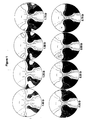
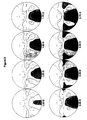
- a progressive ophthalmic lens element including a lens surface having an upper viewing zone having a surface power corresponding to distance vision, a lower viewing zone having a greater surface power than the upper viewing zone to achieve a refracting power corresponding to near vision; and -an intermediate zone extending across the lens element having a surface power varying from that of the upper viewing zone to that of the lower viewing zone and including a corridor of relatively low surface astigmatism; the lens surface including a relatively high, relatively wide lower viewing zone; and a relatively wide intermediate zone.
- the present invention accordingly provides a progressive ophthalmic lens element exhibiting a balance in zone sizes which provides the wearer with significantly improved near and intermediate vision, thus making spectacles including the progressive ophthalmic lenses more acceptable to the first time or part-time wearer, or a wearer with a near vision priority, and making adaptation thereto a much simpler task.
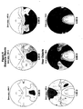
- the area of the lower viewing zone when ray traced to a 0.4 m object distance is over 150 mm 2 .
- the progressive lens design according to this aspect of the present invention may be such that the ratio of the area of clear vision of the upper (or distance) viewing zone to the lower (or near) viewing zone is in the range between approximately 2.50 and 3.00.
- This clear vision size ratio is indicative of effective relative zone sizes and illustrates the improved balance of zone sizes between the distance and near viewing zones in the ophthalmic lens elements for wearers with a near vision priority according to the present invention.
- the progressive design lens according to this aspect of the present invention includes a surface design of the peripheral regions of the lens to reduce or minimise the phenomenon of "swim".
- swipe we mean wearer perception of the unnatural movement of objects within the visual field during dynamic visual tasks, which may lead to a sense of unsteadiness, dizziness or nausea.
- the lens surface areas that are critical for reducing the swim sensation are within a pair of generally horizontally disposed opposed segments approximately ⁇ 22.5° above and below a generally horizontal axis passing through the fitting cross. -
- the opposed segments may have a radius of approximately 15 mm from the fitting cross, preferably approximately 20 mm, more preferably approximately 25 mm.
- the minimisation of the swimming sensation may be achieved by reducing optical aberrations contributing to swim.
- a surface correction(s) may provide a reduction in the sagittal addition power within the opposed segments.
- the surface(s) may be such that the difference between maximum and minimum sagittal addition power is less than approximately 0.75* Add diopters. This may significantly reduce the phenomenon of swim for a wearer, in use.
- the progressive lens design may exhibit a small amount of addition power (eg. 0.05 D to 0.4 D), proximate the fitting cross depending on the nominal addition power of the lens element and the base curve.
- a small amount of addition power eg. 0.05 D to 0.4 D
- the corridor of the intermediate viewing zone is thus effectively extended a small distance into the upper (or distance) viewing zone, allowing peripheral blur values to be reduced and the zone available for clear vision at intermediate distances to be increased.
- the ophthalmic lens element according to the present invention may form one of a series of lens elements.
- each lens element including a lens surface having an upper viewing zone having a surface power to achieve a refracting power corresponding to distance vision; a lower viewing zone having a greater surface power than the upper viewing zone to achieve a refracting power corresponding to near vision; and an intermediate zone extending across the lens element having a surface power varying from that of the upper viewing zone to that of the lower viewing zone and including a corridor of relatively low surface astigmatism;
- the progressive ophthalmic lens series including lens elements having a base curve suitable for use in providing a range of distance prescriptions for one or more of emmetropes, hyperopes and myopes, each lens element differing in prescribed addition power and including a progressive design including a relatively high, relatively wide lower viewing zone and a relatively wide intermediate zone; the dimensions of the intermediate and lower viewing zones being related to the prescribed addition power of the wearer.
- the present invention accordingly relates to a progressive ophthalmic lens series exhibiting improved functionality and ease of adaptation, as it takes into account factors including one or more of the following: wearers' sensitivity to swim and natural eye movements.
- the progressive lens element within the series also exhibits a distance/near zone balance more appropriate for a part-time wearer or a wearer with a near vision priority than those provided by general purpose prior art progressive lenses.
- each progressive ophthalmic lens element in a series according to the present invention exhibits a relatively high lower viewing, or near vision, zone.
- the relatively high lower viewing zone may reduce the need for the wearer to learn new head postures for reading purposes.
- the lens elements having a base curve suitable for emmetropes have an upper viewing zone and lower viewing zone such that the ratio of the area of clear vision of the upper viewing zone to the lower viewing zone is in the range between approximately 2.50 and 3.00.
- each lens element in the series may have a progressive lens design exhibiting a small amount of addition power proximate the fitting cross; the addition power component proximate the fitting cross being related to the prescribed addition power and/or depth of focus of the wearer.
- the addition power proximate the fitting cross of a progressive lens element is in the range from 0.05 to 0.40 D, the fitting cross addition power increasing with the addition power for each of the base curves, and with the increasing base curve for each addition power.
- the lens elements may exhibit an increase in corridor length within increasing addition power.
- the relatively high, relatively wide lower viewing zone may permit useful reading from a point (the highest reading point) approximately 10 to 12 mm below the fitting cross.
- the effective corridor length is approximately 10 to 12 mm.
- the lower viewing zone may permit useful reading from a point (the highest reading point) approximately 12 mm below the fitting cross. Then the effective corridor length is approximately 12 mm. It will be understood that the slight increase in effective corridor length at higher addition powers permits an increased effective lower or near viewing zone size and/or lower peripheral blur.
- highest reading point we mean the highest point along the eye path where the wearer can read normal size text at the 40 cm reading distance without perceiving the blur. This is equal to the nominal prescribed add minus the effective depth of focus for near vision which is around 0.50 D for a broad range of addition powers.
- the progressive lens design of each lens element in this series includes a surface correction to reduce or minimise the phenomenon of "swim".
- the surface modification to reduce swim may be provided within a pair of generally horizontally disposed opposed segments generally centred at the fitting cross of each ophthalmic lens element.
- the opposed segments may extend approximately ⁇ 22.5° above and below a generally horizontal axis passing through the fitting cross.
- the opposed segments may have a radius of approximately 15 mm from the fitting cross, preferably approximately 20 mm, more preferably approximately 25 mm.
- the swim surface correction(s) may be such as to reduce optical aberrations contributing to swim.
- the swim surface correction(s) may take the form of a reduction in the sagittal addition power variations within the segments defined above.
- the difference between maximum and minimum sagittal addition power within the opposed segments is less than approximately 0.75*Add (in diopters)
- each lens element within the series exhibits a substantially constant ratio of the area of clear vision of the upper (or distance) viewing zone to the lower (or near) viewing zone for all addition powers.
- the clear vision zone size ratio may generally be in the range between approximately 2.50 and 3.00.
- the generally constant clear vision zone size ratio may thus provide the wearer with a generally constant area for clear foveal vision independent of addition power.
- the progressive lens design of each lens element within the series exhibits a substantially constant area of clear vision on the lens surface within the lower viewing zone for a specified base curve. Accordingly the design of each progressive lens element within the series provides the wearer with a generally constant, improved area of clear vision for near tasks across a range of addition powers.
- the lens element series according to Claim 21 wherein the lens element series exhibits a slight decrease in the area of the zone clear for distance vision on the lens surface inside a 22 mm radius circle centred on the GC and constrained by the Add/4 diopters RMS power error contour ray traced in the as worn configuration for an infinite object distance with increasing base curve.
- corridor we mean an area of the intermediate zone of varying power bounded by nasal and temporal contours of tolerable aberration for foveal vision.
- the corridor has a "corridor length" (L), which corresponds to the length of the segment of the visual fixation locus which extends from the vertical height of the fitting cross (FC) to the vertical height of the near zone measurement point.
- L the length of the segment of the visual fixation locus which extends from the vertical height of the fitting cross (FC) to the vertical height of the near zone measurement point.
- the power progression begins at the fitting cross (FC) height.
- effective corridor length as used herein we mean the length from the “fitting cross” (FC) to the highest reading point (HRP) on the lens surface.
- lens element we mean all forms of individual refractive optical bodies employed in the ophthalmic arts, including, but not limited to, lenses, lens wafers and semi-finished lens blanks requiring further finishing to a particular patient's prescription. Also included are formers used in the manufacture of progressive glass lenses and moulds for the casting of progressive lenses in polymeric material such as the material sold under the trade designation CR39.
- tigmatism or surface astigmatism we mean a measure of the degree to which the curvature of the lens varies among intersecting planes which are normal to the surface of the lens at a point on the surface.
- each lens element includes a surface correction to improve optical properties proximate the peripheries of the lens element.
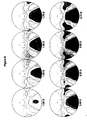
- the distribution of RMS power error may be varied proximate the peripheries of the upper (distance) and/or lower (near) viewing zones.
- the distribution of RMS power error exhibits a relatively low gradient proximate the distance periphery and a relatively high gradient proximate the near periphery.
- the relative values of these gradients can be quantified by examining the ratio of the maximum vertical rate of change of the ray traced RMS power error along the 12 mm long vertical lines centred on the fitting cross (FC) and horizontally offset 15 mm from the FC, to the maximum horizontal rate of change - of the RMS power error at the level of the near vision measurement point (NMP).
- this ratio may be less than approximately 0.60 and may preferably vary from approximately 0.40 to 0.60.
- the location of the corridor of the ophthalmic lens element may be dictated at least in part by the visual fixation locus; the visual fixation locus being inset generally horizontally nasally below the fitting cross (FC) of the lens element.
- visual fixation locus we mean the set of points which are the intersection of the lens surface and the patient's line of sight as he or she fixates on objects in the median plane. The term does not signify a required, continuous eye movement path. Rather, the visual fixation locus indicates the set of points corresponding to variously positioned objects in the median plane.
- the visual fixation locus takes into account the fact that the wearer may or may not use the accommodative reserve for a particular fixation. As a result, points at different locations in the visual fixation locus are provided having a power sufficient for comfortable use at the appropriate object distances.
- the fitting cross (FC) is generally located at (0,y FC ).
- the value of y FC may vary, for example, from approximately 2 mm to 6 mm above the geometric centre of the lens element.
- a method of designing an ophthalmic lens element including a first lens surface having an upper viewing zone having a surface power corresponding to distance vision, a lower viewing zone having a greater surface power than the upper viewing zone to achieve a refracting power corresponding to near vision; and an intermediate zone extending across the lens element having a surface power varying from that of the upper viewing zone to that of the lower viewing zone and including a corridor of relatively low surface astigmatism; the ophthalmic lens element including a relatively high, relatively wide lower viewing zone; and a relatively wide intermediate zone, which method includes selecting a merit function relating to at least one optical characteristic of the lens to be minimised with an appropriate distribution of the optimisation weights on the lens surface; and solving the global minimisation problem using the Finite Element Method; and fabricating an ophthalmic lens element having a lens surface shaped according to said optimised surface description.
- the ophthalmic lens element may be formulated from any suitable material.
- a polymeric material may be used.
- the polymeric material may be of any suitable type.
- the polymeric material may include a thermoplastic or thermoset material.
- a material of the diallyl glycol carbonate type, for example CR-39 (PPG Industries) may be used.
- the polymeric article may be formed from cross-linkable polymeric casting compositions, for example as described in Applicants' United States Patent 4,912,155 , United States Patent Application No. 07/781,392 , Australian Patent Applications 50581/93 , 50582/93 , 81216/87 , 74160/91 and European Patent Specification 453159A2 , the entire disclosures of which are incorporated herein by reference.
- the polymeric material may include a dye, preferably a photochromic dye, which may, for example, be added to the monomer formulation used to produce the polymeric material.
- the ophthalmic lens element according to the present invention may further include standard additional coatings to the front or back surface, including electrochromic coatings.
- the front lens surface may include an anti-reflective (AR) coating, for example of the type described in United States Patent 5,704,692 to Applicants, the entire disclosure of which is incorporated herein by reference.
- AR anti-reflective
- the front lens surface may include an abrasion resistant coating. e.g. of the type described in United States Patent 4,954,591 to Applicants, the entire disclosure of which is incorporated herein by reference.
- the front and back surfaces may further include one or more additions conventionally used in casting compositions such as inhibitors, dyes including thermochromic and photochromic dyes, e.g. as described above, polarising agents, UV stabilisers and materials capable of modifying refractive index.
Landscapes
- Health & Medical Sciences (AREA)
- Ophthalmology & Optometry (AREA)
- Physics & Mathematics (AREA)
- General Health & Medical Sciences (AREA)
- General Physics & Mathematics (AREA)
- Optics & Photonics (AREA)
- Eyeglasses (AREA)
Abstract
Claims (32)
- Elément de lentille ophtalmique progressive comprenant une surface de lentille ayant
une zone de vision supérieure ayant une puissance surfacique correspondant à une vision de loin,
une zone de vision inférieure ayant une puissance surfacique plus élevée que la zone de vision supérieure afin d'obtenir une puissance de réfraction correspondant à une vision de près ; et
une zone intermédiaire s'étendant à travers l'élément de lentille ayant une puissance surfacique variant de celle de la zone de vision supérieure à celle de la zone de vision inférieure et comprenant un couloir d'astigmatisme de surface relativement faible ;
la surface de la lentille comprenant
une zone intermédiaire et une zone de vision inférieure fournissant une longueur de couloir efficace d'environ 10 à environ 12 mm ;
caractérisé en ce que la zone de vision supérieure et la zone de vision inférieure sont telles que le rapport de la surface de vision nette de la zone de vision supérieure sur la zone de vision inférieure est inférieur à environ 3,00 et supérieur à environ 2,50 ; et
dans lequel la surface de vision nette est déterminée en traçant un rayon sur la lentille dans la configuration portée pour une distance d'objet spécifique, la distance d'objet spécifique étant infinie pour la vision de loin et 0,4 m pour la vision de près, et en calculant la surface à l'intérieur d'un contour de dioptrie Add/4 de l'erreur de puissance RMS à l'intérieur d'un cercle de rayon de 22 mm centré sur le centre géométrique de la lentille. - Lentille ophtalmique progressive selon la revendication 1, dans laquelle la surface de la zone de vision inférieure est supérieure à environ 150 mm2.
- Elément de lentille ophtalmique progressive selon la revendication 2, dans lequel la hauteur de la zone de vision inférieure définie par le contour d'erreur de puissance RMS de dioptries Add/4 est dans la plage d'environ 10 à 12 mm en dessous de la croix de montage.
- Elément de lentille ophtalmique progressive selon la revendication 1, comprenant en outre une (des) correction(s) de surface dans les régions périphériques de l'élément de lentille qui sert (servent) à réduire ou minimiser des aberrations optiques contribuant au phénomène d'ondulation.
- Elément de lentille ophtalmique progressive selon la revendication 4, dans lequel la (les) correction(s) de surface sert (servent) à réduire les aberrations optiques dans les surfaces de lentille comprenant une paire de secteurs opposés généralement disposés horizontalement d'environ ±22,5° au-dessus et en dessous d'un axe généralement horizontal passant à travers la croix de montage de l'élément de lentille.
- Elément de lentille ophtalmique progressive selon la revendication 5, dans lequel les secteurs opposés ont un rayon d'environ 15 mm à partir de la croix de montage.
- Elément de lentille ophtalmique progressive selon la revendication 5, dans lequel les secteurs opposés ont un rayon d'environ 20 mm à partir de la croix de montage.
- Elément de lentille ophtalmique progressive selon la revendication 4, dans lequel la (les) correction(s) de surface fournit (fournissent) une réduction de la variation de la puissance ajoutée sagittale à l'intérieur des secteurs opposés.
- Elément de lentille ophtalmique progressive selon la revendication 8, dans lequel la (les) correction(s) de surface est (sont) telle(s) que la différence entre la puissance ajoutée sagittale maximale et la puissance ajoutée sagittale minimale est inférieure à environ 0,75* dioptrie Add.
- Elément de lentille ophtalmique progressive selon la revendication 1, dans lequel la conception de lentille présente une petite quantité de puissance ajoutée à proximité de la croix de montage, en fonction de la puissance ajoutée nominale de l'élément de lentille.
- Elément de lentille ophtalmique progressive selon la revendication 10, dans lequel la conception de lentille présente environ 0,05 D à 0,4 D de puissance ajoutée à proximité de la croix de montage, en fonction de la puissance ajoutée nominale de l'élément de lentille.
- Elément de lentille ophtalmique progressive selon la revendication 1, comprenant en outre une correction de surface pour améliorer les propriétés optiques à proximité des périphéries de l'élément de lentille.
- Elément de lentille ophtalmique progressive selon la revendication 12, dans lequel la répartition de l'erreur de puissance RMS varie à proximité des périphéries des zones de vision supérieure et/ou inférieure pour améliorer la vision périphérique.
- Série d'éléments de lentille ophtalmique progressive selon la revendication 13, dans laquelle la répartition de l'erreur de puissance RMS présente un gradient relativement faible à proximité de la périphérie éloignée et un gradient relativement élevé à proximité de la périphérie proche.
- Elément de lentille ophtalmique progressive selon la revendication 14, dans lequel le rapport de la vitesse de changement maximale de l'erreur de puissance RMS tracée par rayon le long de lignes verticales de 12 mm de long centrées sur la croix de montage (FC) et décalées horizontalement de 15 mm par rapport à la FC sur la vitesse de changement horizontale maximale de l'erreur de puissance RMS au niveau du point de mesure de vision de près (NMP) varie d'environ 0,4 à environ 0,8.
- Série d'éléments de lentille ophtalmique progressive, chaque élément de lentille comprenant une surface de lentille ayant
une zone de vision supérieure ayant une puissance surfacique pour obtenir une puissance de réfraction correspondant à une vision de loin ;
une zone de vision inférieure ayant une puissance surfacique plus élevée que la zone de vision supérieure afin d'obtenir une puissance de réfraction correspondant à la vision de près ; et
une zone intermédiaire s'étendant à travers l'élément de lentille ayant une puissance surfacique variant de celle de la zone de vision supérieure à celle de la zone de vision inférieure et comprenant un couloir d'astigmatisme de surface relativement faible ;
la série de lentilles ophtalmiques progressives comprenant
des éléments de lentille ayant une courbure de base adéquate pour fournir une plage de prescriptions de distance pour un ou plusieurs emmétropes, hyperopes et myopes, chaque élément de lentille ayant une puissance ajoutée prescrite différente et comprenant une conception progressive incluant
une zone intermédiaire et une zone de vision inférieure fournissant une longueur de couloir efficace d'environ 10 à environ 12 mm ;
caractérisée en ce que la zone de vision supérieure et la zone de vision inférieure sont telles que le rapport de la surface de vision nette de la zone de vision supérieure sur la zone de vision inférieure est inférieur à environ 3,00 et supérieur à environ 2,50 ; et
dans laquelle la surface de vision nette est déterminée en traçant un rayon sur la lentille dans la configuration portée pour une distance d'objet spécifique, la distance d'objet spécifique étant infinie pour la vision de loin et de 0,4 m pour la vision de près, et en calculant la surface à l'intérieur d'un contour de dioptrie Add/4 de l'erreur de puissance RMS à l'intérieur d'un cercle de rayon de 22 mm centré sur le centre géométrique de la lentille,
les dimensions des zones de vision intermédiaire et inférieure étant relatives à la puissance ajoutée prescrite de l'utilisateur. - Série d'éléments de lentille ophtalmique progressive selon la revendication 16, dans laquelle chaque élément de lentille dans la série a une conception de lentille progressive présentant une petite quantité de puissance ajoutée à proximité de la croix de montage, en fonction de la puissance ajoutée prescrite et de la courbure de base.
- Série de lentilles ophtalmiques progressives selon la revendication 17, dans laquelle la puissance ajoutée à proximité de la croix de montage d'un élément de lentille progressif est dans la plage de 0,05 à 0,40 D, la puissance ajoutée de la croix de montage augmentant avec la puissance ajoutée pour chacune des courbures de base, et avec la courbure de base croissante pour chaque puissance ajoutée.
- Série d'éléments de lentille ophtalmique progressive selon la revendication 17, dans laquelle la série d'éléments de lentille présente une légère diminution de la surface de la zone de vision nette pour la vision de loin sur la surface de lentille à l'intérieur d'un cercle de rayon de 22 mm centré sur la GC et limité par le rayon de contour d'erreur de puissance RMS de dioptries Add/4 tracé dans la configuration portée pour une distance d'objet infinie avec une courbure de base croissante.
- Série d'éléments de lentille ophtalmique progressive selon la .revendication 19, dans laquelle les éléments de lentille présentent une augmentation de longueur de couloir à l'intérieur d'une puissance ajoutée croissante.
- Série d'éléments de lentille ophtalmique progressive selon la revendication 20, dans laquelle pour des puissances ajoutées faibles à moyennes, les éléments de lentille présentent une croissance de la longueur de couloir efficace d'environ 10 à 12 mm ; et pour des puissances ajoutées plus élevées, présentent une longueur de couloir d'environ 12 mm.
- Série d'éléments de lentille ophtalmique progressive selon la revendication 16, dans laquelle la conception de lentille progressive de chaque élément de lentille dans la série comprend une (des) correction(s) de surface dans les régions périphériques de l'élément de lentille pour réduire ou minimiser le phénomène d'ondulation.
- Série d'éléments de lentille ophtalmique progressive selon la revendication 22, dans laquelle la (les) correction(s) de surface sert (servent) à réduire les aberrations optiques dans les surfaces de lentille incluant une paire de secteurs opposés généralement disposés horizontalement d'environ ± 22,5° au-dessus et en dessous d'un axe généralement horizontal passant à travers la croix de montage.
- Série d'éléments de lentille ophtalmique progressive selon la revendication 23, dans laquelle les secteurs opposés ont un rayon d'environ 15 mm ou plus.
- Série d'éléments de lentille ophtalmique progressive selon la revendication 24, dans laquelle la correction de surface prend la forme d'une réduction dans les variations de puissance ajoutée sagittale à l'intérieur de chacun des secteurs opposés.
- Série d'éléments de lentille ophtalmique progressive selon la revendication 25, dans laquelle la différence entre la puissance ajoutée sagittale maximale et la puissance ajoutée sagittale minimale à l'intérieur de chacun des secteurs opposés est inférieure à environ 0,75* dioptrie Add.
- Série d'éléments de lentille ophtalmique progressive selon la revendication 16, dans laquelle chaque élément au sein de la série présente une surface sensiblement constante de vision nette sur la surface de lentille à l'intérieur de la zone de vision inférieure.
- Série d'éléments de lentille ophtalmique progressive selon la revendication 16, dans laquelle chaque élément de lentille comprend une correction de surface pour améliorer les propriétés optiques à proximité des périphéries de l'élément de lentille.
- Série d'éléments de lentille ophtalmique progressive selon la revendication 28, dans laquelle la répartition de l'erreur de puissance RMS varie à proximité des périphéries des zones de vision supérieure et/ou inférieure pour améliorer la vision périphérique.
- Série d'éléments de lentille ophtalmique progressive selon la revendication 29, dans laquelle la répartition de l'erreur de puissance RMS présente un gradient relativement faible à proximité de la périphérie éloignée et un gradient relativement élevé à proximité de la périphérie proche.
- Série d'éléments de lentille ophtalmique progressive selon la revendication 30, dans laquelle les éléments de base ont un rapport de la vitesse de changement maximale de l'erreur de puissance RMS tracée par rayon le long de lignes verticales de 12 mm de long centrées sur la croix de montage (FC) et décalées horizontalement de 15 mm de la FC sur la vitesse de changement horizontale de l'erreur de puissance RMS au niveau du point de mesure de vision de près (NMP) qui varie d'environ 0,4 à environ 0,6.
- Procédé de conception d'un élément de lentille ophtalmique comprenant une première surface de lentille ayant
une zone de vision supérieure ayant une puissance surfacique correspondant à une vision de loin,
une zone de vision inférieure ayant une puissance surfacique plus élevée que la zone de vision supérieure afin d'obtenir une puissance de réfraction correspondant à une vision de près ; et
une zone intermédiaire s'étendant à travers l'élément de lentille ayant une puissance surfacique variant de celle de la zone de vision supérieure à celle de la zone de vision inférieure et comprenant
un couloir d'astigmatisme de surface relativement faible, l'élément de lentille ophtalmique comprenant
une zone intermédiaire et une zone de vision inférieure fournissant une longueur de couloir efficace d'environ 10 à environ 12 mm ;
dans lequel la zone de vision supérieure et la zone de vision inférieure sont telles que le rapport de la zone de vision nette de la zone de vision supérieure sur la zone de vision inférieure est inférieur à environ 3,00 et supérieur à environ 2,50 ; et
dans lequel la zone de vision nette est déterminée en traçant un rayon sur la lentille dans la configuration portée pour une distance d'objet spécifique, la distance d'objet spécifique étant infinie pour la vision de loin et de 0,4 m pour la vision de près, et en calculant la surface à l'intérieur d'un contour de dioptrie Add/4 de l'erreur de puissance RMS à l'intérieur d'un cercle de rayon 22 mm centré sur le centre géométrique de la lentille ;
lequel procédé consiste à
sélectionner une fonction de mérite relative à au moins une caractéristique optique de la lentille devant être minimisée avec une répartition appropriée des poids d'optimisation sur la surface de lentille ; et
résoudre le problème de minimisation global en utilisant le procédé des éléments finis ; et
fabriquer un élément de lentille ophtalmique ayant une surface de lentille façonnée selon ladite description de surface optimisée.
Applications Claiming Priority (5)
| Application Number | Priority Date | Filing Date | Title |
|---|---|---|---|
| AUPP322099 | 1999-10-01 | ||
| AUPQ3220A AUPQ322099A0 (en) | 1999-10-01 | 1999-10-01 | Progressive lens |
| AUPQ3269A AUPQ326999A0 (en) | 1999-10-05 | 1999-10-05 | Progressive lens |
| AUPP326999 | 1999-10-05 | ||
| PCT/AU2000/001196 WO2001025837A1 (fr) | 1999-10-01 | 2000-09-29 | Lentille progressive |
Publications (3)
| Publication Number | Publication Date |
|---|---|
| EP1216432A1 EP1216432A1 (fr) | 2002-06-26 |
| EP1216432A4 EP1216432A4 (fr) | 2005-05-18 |
| EP1216432B1 true EP1216432B1 (fr) | 2009-03-04 |
Family
ID=25646164
Family Applications (1)
| Application Number | Title | Priority Date | Filing Date |
|---|---|---|---|
| EP00969060A Expired - Lifetime EP1216432B1 (fr) | 1999-10-01 | 2000-09-29 | Lentille progressive |
Country Status (5)
| Country | Link |
|---|---|
| US (1) | US6793340B1 (fr) |
| EP (1) | EP1216432B1 (fr) |
| CA (1) | CA2386062A1 (fr) |
| MX (1) | MXPA02003264A (fr) |
| WO (1) | WO2001025837A1 (fr) |
Families Citing this family (45)
| Publication number | Priority date | Publication date | Assignee | Title |
|---|---|---|---|---|
| US6619799B1 (en) | 1999-07-02 | 2003-09-16 | E-Vision, Llc | Optical lens system with electro-active lens having alterably different focal lengths |
| US7775660B2 (en) | 1999-07-02 | 2010-08-17 | E-Vision Llc | Electro-active ophthalmic lens having an optical power blending region |
| BR0214533A (pt) * | 2001-12-05 | 2004-11-09 | Sola Int Holdings | Lente progressiva balanceadas |
| AU2002365669B2 (en) * | 2001-12-05 | 2007-11-29 | Carl Zeiss Vision Australia Holdings Ltd | Balanced progressive lens |
| AUPR949101A0 (en) * | 2001-12-14 | 2002-01-24 | Sola International Holdings Ltd | Method for prescribing and/or dispensing ophthalmic lenses |
| US8915588B2 (en) | 2004-11-02 | 2014-12-23 | E-Vision Smart Optics, Inc. | Eyewear including a heads up display |
| US8778022B2 (en) | 2004-11-02 | 2014-07-15 | E-Vision Smart Optics Inc. | Electro-active intraocular lenses |
| US9801709B2 (en) | 2004-11-02 | 2017-10-31 | E-Vision Smart Optics, Inc. | Electro-active intraocular lenses |
| FR2884325B1 (fr) * | 2005-04-08 | 2007-06-01 | Essilor Int | Lentille ophtalmique |
| JP2008541142A (ja) * | 2005-05-05 | 2008-11-20 | カール ツァイス ビジョン オーストラリア ホールディングス リミテッド | 累進めがねレンズ要素の列 |
| FR2888344B1 (fr) * | 2005-07-11 | 2007-09-14 | Essilor Int | Lentille ophtalmique |
| FR2893151B1 (fr) * | 2005-11-08 | 2008-02-08 | Essilor Int | Lentille ophtalmique. |
| FR2894038B1 (fr) * | 2005-11-29 | 2008-03-07 | Essilor Int | Lentille ophtalmique. |
| FR2895092B1 (fr) | 2005-12-16 | 2008-02-29 | Essilor Int | Procede de determination d'une lentille ophtalmique. |
| CA2644775C (fr) * | 2006-03-08 | 2012-06-05 | Scientific Optics, Inc. | Procede et appareil d'amelioration universelle de la vision |
| KR101444480B1 (ko) * | 2006-09-15 | 2014-09-24 | 칼 자이스 비전 오스트레일리아 홀딩스 리미티드 | 누진다초점 안 렌즈용 굴절 광학체 및 이를 디자인하는 방법 |
| AR064985A1 (es) | 2007-01-22 | 2009-05-06 | E Vision Llc | Lente electroactivo flexible |
| US20080189838A1 (en) * | 2007-02-12 | 2008-08-14 | Mage Jerome J M | Multi-base lens goggle |
| BRPI0807560A2 (pt) | 2007-02-23 | 2014-07-01 | Pixeloptics Inc | Abertura oftálmica dinâmica |
| CA2679977A1 (fr) | 2007-03-07 | 2008-09-18 | Pixeloptics, Inc. | Lentille multifocale possedant une region de puissance optique progressive et une discontinuite |
| US20080273169A1 (en) | 2007-03-29 | 2008-11-06 | Blum Ronald D | Multifocal Lens Having a Progressive Optical Power Region and a Discontinuity |
| US7883207B2 (en) | 2007-12-14 | 2011-02-08 | Pixeloptics, Inc. | Refractive-diffractive multifocal lens |
| FR2916864B1 (fr) * | 2007-05-31 | 2010-01-08 | Essilor Int | Verre ophtalmique progressif de correction de myopie et procede de realisation d'un tel verre |
| US7926941B2 (en) * | 2007-12-14 | 2011-04-19 | Pixeloptics Inc. | Multiple layer multifocal composite lens |
| US7744215B2 (en) * | 2007-12-25 | 2010-06-29 | Pixeloptics, Inc. | Multiple layer multifocal composite lens |
| AU2009225638A1 (en) | 2008-03-18 | 2009-09-24 | Pixeloptics, Inc. | Advanced electro-active optic device |
| US8154804B2 (en) | 2008-03-25 | 2012-04-10 | E-Vision Smart Optics, Inc. | Electro-optic lenses for correction of higher order aberrations |
| NL2002540C2 (en) * | 2009-02-17 | 2010-08-18 | Oculentis B V | Ophthalmic lens with optical sectors. |
| EP2246729A1 (fr) | 2009-04-30 | 2010-11-03 | Essilor International (Compagnie Générale D'Optique) | Procédé pour évaluer une propriété optique d'un dessin de lentille ophtalmique |
| JP5851411B2 (ja) * | 2009-11-09 | 2016-02-03 | カール ツァイス ビジョン インターナショナル ゲーエムベーハー | 眼鏡レンズ部材 |
| BR112014016460A8 (pt) | 2012-01-06 | 2017-07-04 | Hpo Assets Llc | docking station para uso em óculos e módulo eletrônico |
| WO2015150269A1 (fr) * | 2014-04-01 | 2015-10-08 | Essilor International (Compagnie Generale D'optique) | Verre de lunettes ophtalmique multifocal agencé pour transmettre une image supplémentaire |
| EP3440508B1 (fr) | 2016-04-12 | 2021-01-27 | E- Vision Smart Optics, Inc. | Lentilles électroactives avec ponts résistifs surélevés |
| US10599006B2 (en) | 2016-04-12 | 2020-03-24 | E-Vision Smart Optics, Inc. | Electro-active lenses with raised resistive bridges |
| IL249288A0 (en) * | 2016-11-29 | 2017-03-30 | Shamir Optical Ind Ltd | Ophthalmic lens |
| US10330950B2 (en) | 2017-02-23 | 2019-06-25 | Indizen Optical Technologies of America, LLC | Progressive lenses with reduced peripheral mean sphere |
| US11209671B2 (en) * | 2018-08-20 | 2021-12-28 | Shamir Optical Industry Ltd. | Progressive optical designs for different add powers |
| JP7249357B2 (ja) * | 2018-09-28 | 2023-03-30 | ホヤ レンズ タイランド リミテッド | 累進屈折力レンズの設計システム、累進屈折力レンズの設計方法、累進屈折力レンズの製造方法および累進屈折力レンズ群 |
| US11583388B2 (en) | 2019-04-05 | 2023-02-21 | Amo Groningen B.V. | Systems and methods for spectacle independence using refractive index writing with an intraocular lens |
| US11564839B2 (en) | 2019-04-05 | 2023-01-31 | Amo Groningen B.V. | Systems and methods for vergence matching of an intraocular lens with refractive index writing |
| US11529230B2 (en) | 2019-04-05 | 2022-12-20 | Amo Groningen B.V. | Systems and methods for correcting power of an intraocular lens using refractive index writing |
| US11944574B2 (en) | 2019-04-05 | 2024-04-02 | Amo Groningen B.V. | Systems and methods for multiple layer intraocular lens and using refractive index writing |
| US11583389B2 (en) | 2019-04-05 | 2023-02-21 | Amo Groningen B.V. | Systems and methods for correcting photic phenomenon from an intraocular lens and using refractive index writing |
| US11678975B2 (en) | 2019-04-05 | 2023-06-20 | Amo Groningen B.V. | Systems and methods for treating ocular disease with an intraocular lens and refractive index writing |
| US11520308B2 (en) | 2020-07-29 | 2022-12-06 | Indizen Optical Technologies of America, LLC | Progressive lenses with variable reduced peripheral mean sphere |
Family Cites Families (44)
| Publication number | Priority date | Publication date | Assignee | Title |
|---|---|---|---|---|
| US2878721A (en) | 1954-02-03 | 1959-03-24 | Farrand Optical Co Inc | Multifocal ophthalmic lenses |
| DE2610203B2 (de) * | 1976-03-11 | 1981-01-22 | Optische Werke G. Rodenstock, 8000 Muenchen | Progressives Brillenglas |
| DE2814916C3 (de) * | 1978-04-06 | 1982-01-07 | Optische Werke G. Rodenstock, 8000 München | Brillenglas mit einem zwischen Fernteil und Nahteil liegenden Progressionsbereich |
| US4676610A (en) | 1983-07-22 | 1987-06-30 | Sola International Holdings Ltd. | Method of making progressive lens surface and resulting article |
| US5771089A (en) | 1984-08-17 | 1998-06-23 | Optische Werke G. Rodenstock | Progressive spectacle lens |
| FR2588973B1 (fr) * | 1985-10-23 | 1988-01-08 | Essilor Int | Lentille ophtalmique progressive |
| GB8528460D0 (en) * | 1985-11-19 | 1985-12-24 | Sola Int Holdings | Multifocal lens |
| US4861153A (en) | 1986-12-19 | 1989-08-29 | American Optical Corporation | Progressive addition spectacle lens |
| US4838675A (en) | 1987-06-19 | 1989-06-13 | Sola International Holdings, Ltd. | Method for improving progressive lens designs and resulting article |
| DE4012609A1 (de) | 1990-04-19 | 1991-10-24 | Zeiss Carl Fa | Gleitsichtflaeche fuer eine gleitsichtbrillenlinse |
| DE4210008A1 (de) | 1992-03-27 | 1993-09-30 | Zeiss Carl Fa | Brillenlinse |
| FR2699294B1 (fr) | 1992-12-11 | 1995-02-10 | Essilor Int | Lentille ophtalmique multifocale progressive. |
| US5920372A (en) | 1992-12-15 | 1999-07-06 | Optische Werke G. Rodenstock | Ophthalmic lens having an astigmatic effect |
| DE4242267A1 (de) * | 1992-12-15 | 1994-06-16 | Rodenstock Optik G | Brillenglas mit astigmatischer Wirkung |
| FR2701770B1 (fr) * | 1993-02-18 | 1995-05-12 | Essilor Int | Lentille ophtalmique à vision simultanée pour la correction de la presbytie et jeu de deux telles lentilles ophtalmiques pour un même porteur . |
| FR2704327B1 (fr) * | 1993-04-23 | 1995-06-23 | Essilor Int | Paire de lentilles ophtalmiques multifocales progressives. |
| CN1053278C (zh) | 1994-10-21 | 2000-06-07 | 索拉国际控股有限公司 | 改进的眼镜片 |
| FR2726374B1 (fr) | 1994-10-28 | 1996-12-27 | Essilor Int | Lentille ophtalmique multifocale progressive |
| JP3196877B2 (ja) | 1995-04-18 | 2001-08-06 | ホーヤ株式会社 | 累進多焦点レンズ |
| FR2733328B1 (fr) | 1995-04-21 | 1997-06-13 | Essilor Int | Lentille ophtalmique multifocale progressive |
| IL117937A0 (en) | 1995-05-04 | 1996-08-04 | Johnson & Johnson Vision Prod | Combined multifocal toric lens designs |
| JP3674992B2 (ja) * | 1995-08-08 | 2005-07-27 | 株式会社ニコン | 累進焦点レンズ |
| JP3196880B2 (ja) | 1995-09-22 | 2001-08-06 | ホーヤ株式会社 | 累進多焦点レンズ |
| EP0809126B1 (fr) | 1995-11-24 | 2003-03-19 | Seiko Epson Corporation | Verres de lunettes progressifs ayant la face progressive et la correction d astigmatisme sur la face posterieure |
| JPH09251143A (ja) * | 1996-03-14 | 1997-09-22 | Nikon Corp | 累進焦点レンズ |
| WO1997038343A1 (fr) | 1996-04-04 | 1997-10-16 | Sola International Holdings Ltd. | Elements lentilles de contact progressives et procedes de fabrication et d'utilisation desdites lentilles |
| AUPN944096A0 (en) | 1996-04-24 | 1996-05-16 | Sola International Holdings Ltd | Progressive lens |
| AU713017B2 (en) | 1996-07-05 | 1999-11-18 | Rodenstock Gmbh | Progressive ophthalmic lenses |
| AUPO625797A0 (en) | 1997-04-17 | 1997-05-15 | Sola International Holdings Ltd | Spectacles bearing sunglass lenses |
| BR9808889B1 (pt) | 1997-07-18 | 2011-06-28 | lente com correção de superfìcie. | |
| AUPO903197A0 (en) * | 1997-09-09 | 1997-10-02 | Sola International Holdings Ltd | Improved progressive lens |
| FR2769997B1 (fr) * | 1997-10-16 | 1999-12-31 | Essilor Int | Lentille ophtalmique multifocale |
| FR2769998B1 (fr) * | 1997-10-16 | 1999-12-31 | Essilor Int | Lentille ophtalmique multifocale |
| US6102544A (en) * | 1997-10-16 | 2000-08-15 | Essilor International | Multifocal ophthalmic lens |
| US6089710A (en) | 1998-07-20 | 2000-07-18 | Oracle Lens Manufacturing Corporation | Single-vision ophthalmic lens series |
| AUPP474898A0 (en) | 1998-07-17 | 1998-08-13 | Sola International Holdings Ltd | Optical lens |
| IL133301A0 (en) | 1998-06-04 | 2001-04-30 | Sola Int Holdings | Shaped ophthalmic lenses |
| US6220704B1 (en) * | 1998-06-12 | 2001-04-24 | Seiko Epson Corporation | Progressive power lens |
| US6343861B1 (en) | 1998-06-12 | 2002-02-05 | Sola International Holdings, Ltd. | Myopia lens |
| US6086203A (en) | 1998-09-03 | 2000-07-11 | Johnson & Johnson Vision Care, Inc. | Progressive addition lenses |
| US6505930B1 (en) | 1998-10-21 | 2003-01-14 | Sola International Holdings, Ltd. | Spectacles frames for shaped lens elements |
| US6149271A (en) * | 1998-10-23 | 2000-11-21 | Innotech, Inc. | Progressive addition lenses |
| US6142627A (en) | 1998-12-01 | 2000-11-07 | Sola International, Inc. | Short-corridor progressive lens |
| AUPQ065599A0 (en) | 1999-05-31 | 1999-06-24 | Sola International Holdings Ltd | Progressive lens |
-
2000
- 2000-09-29 CA CA002386062A patent/CA2386062A1/fr not_active Abandoned
- 2000-09-29 MX MXPA02003264A patent/MXPA02003264A/es active IP Right Grant
- 2000-09-29 EP EP00969060A patent/EP1216432B1/fr not_active Expired - Lifetime
- 2000-09-29 WO PCT/AU2000/001196 patent/WO2001025837A1/fr active IP Right Grant
- 2000-09-29 US US10/089,781 patent/US6793340B1/en not_active Expired - Lifetime
Also Published As
| Publication number | Publication date |
|---|---|
| WO2001025837A1 (fr) | 2001-04-12 |
| EP1216432A1 (fr) | 2002-06-26 |
| EP1216432A4 (fr) | 2005-05-18 |
| MXPA02003264A (es) | 2002-09-30 |
| CA2386062A1 (fr) | 2001-04-12 |
| US6793340B1 (en) | 2004-09-21 |
Similar Documents
| Publication | Publication Date | Title |
|---|---|---|
| EP1216432B1 (fr) | Lentille progressive | |
| CA2375162C (fr) | Verre progressif | |
| US7066597B2 (en) | Balanced progressive lens | |
| US7159983B2 (en) | Multifocal lenses for pre-presbyopic individuals | |
| US4274717A (en) | Ophthalmic progressive power lens and method of making same | |
| US20110043752A1 (en) | Multifocal Lens Having A Progressive Optical Power Region and a Discontinuity | |
| US8876288B2 (en) | Progressive multifocal ophthalmic lens | |
| CA2680870A1 (fr) | Lentille multifocale ayant une region de puissance optique progressive et une discontinuite | |
| CA2251948A1 (fr) | Verre progressif | |
| US8757799B2 (en) | Progressive multifocal ophthalmic lens | |
| AU772399B2 (en) | Progressive lens | |
| US8092012B2 (en) | Single vision spectacle lens | |
| AU771955B2 (en) | Progressive lens | |
| Miller | Morris | |
| AU2002365669B2 (en) | Balanced progressive lens | |
| GB1569764A (en) | Progressive power ophthalmic lens | |
| GB1569766A (en) | Multifocal ophthalmic lens | |
| MXPA00004272A (en) | Myopia lens |
Legal Events
| Date | Code | Title | Description |
|---|---|---|---|
| PUAI | Public reference made under article 153(3) epc to a published international application that has entered the european phase |
Free format text: ORIGINAL CODE: 0009012 |
|
| 17P | Request for examination filed |
Effective date: 20020411 |
|
| AK | Designated contracting states |
Kind code of ref document: A1 Designated state(s): AT BE CH CY DE DK ES FI FR GB GR IE IT LI LU MC NL PT SE |
|
| AX | Request for extension of the european patent |
Free format text: AL;LT;LV;MK;RO;SI |
|
| RIN1 | Information on inventor provided before grant (corrected) |
Inventor name: FISHER, SCOTT, WARREN Inventor name: POPE, DAVID ROBERT Inventor name: MORRIS, MICHAEL, ALAN Inventor name: VARNAS, SAULIUS, RAYMOND |
|
| A4 | Supplementary search report drawn up and despatched |
Effective date: 20050405 |
|
| RIC1 | Information provided on ipc code assigned before grant |
Ipc: 7G 02C 7/02 B Ipc: 7G 02C 7/06 A |
|
| GRAP | Despatch of communication of intention to grant a patent |
Free format text: ORIGINAL CODE: EPIDOSNIGR1 |
|
| GRAS | Grant fee paid |
Free format text: ORIGINAL CODE: EPIDOSNIGR3 |
|
| GRAA | (expected) grant |
Free format text: ORIGINAL CODE: 0009210 |
|
| RAP1 | Party data changed (applicant data changed or rights of an application transferred) |
Owner name: CARL ZEISS VISION AUSTRALIA HOLDINGS LTD. |
|
| AK | Designated contracting states |
Kind code of ref document: B1 Designated state(s): AT BE CH CY DE DK ES FI FR GB GR IE IT LI LU MC NL PT SE |
|
| REG | Reference to a national code |
Ref country code: GB Ref legal event code: FG4D |
|
| REG | Reference to a national code |
Ref country code: CH Ref legal event code: EP |
|
| REG | Reference to a national code |
Ref country code: IE Ref legal event code: FG4D |
|
| REF | Corresponds to: |
Ref document number: 60041705 Country of ref document: DE Date of ref document: 20090416 Kind code of ref document: P |
|
| PG25 | Lapsed in a contracting state [announced via postgrant information from national office to epo] |
Ref country code: NL Free format text: LAPSE BECAUSE OF FAILURE TO SUBMIT A TRANSLATION OF THE DESCRIPTION OR TO PAY THE FEE WITHIN THE PRESCRIBED TIME-LIMIT Effective date: 20090304 Ref country code: FI Free format text: LAPSE BECAUSE OF FAILURE TO SUBMIT A TRANSLATION OF THE DESCRIPTION OR TO PAY THE FEE WITHIN THE PRESCRIBED TIME-LIMIT Effective date: 20090304 |
|
| NLV1 | Nl: lapsed or annulled due to failure to fulfill the requirements of art. 29p and 29m of the patents act | ||
| PG25 | Lapsed in a contracting state [announced via postgrant information from national office to epo] |
Ref country code: SE Free format text: LAPSE BECAUSE OF FAILURE TO SUBMIT A TRANSLATION OF THE DESCRIPTION OR TO PAY THE FEE WITHIN THE PRESCRIBED TIME-LIMIT Effective date: 20090604 Ref country code: AT Free format text: LAPSE BECAUSE OF FAILURE TO SUBMIT A TRANSLATION OF THE DESCRIPTION OR TO PAY THE FEE WITHIN THE PRESCRIBED TIME-LIMIT Effective date: 20090304 |
|
| PG25 | Lapsed in a contracting state [announced via postgrant information from national office to epo] |
Ref country code: BE Free format text: LAPSE BECAUSE OF FAILURE TO SUBMIT A TRANSLATION OF THE DESCRIPTION OR TO PAY THE FEE WITHIN THE PRESCRIBED TIME-LIMIT Effective date: 20090304 |
|
| PG25 | Lapsed in a contracting state [announced via postgrant information from national office to epo] |
Ref country code: ES Free format text: LAPSE BECAUSE OF FAILURE TO SUBMIT A TRANSLATION OF THE DESCRIPTION OR TO PAY THE FEE WITHIN THE PRESCRIBED TIME-LIMIT Effective date: 20090615 Ref country code: PT Free format text: LAPSE BECAUSE OF FAILURE TO SUBMIT A TRANSLATION OF THE DESCRIPTION OR TO PAY THE FEE WITHIN THE PRESCRIBED TIME-LIMIT Effective date: 20090818 |
|
| PLBE | No opposition filed within time limit |
Free format text: ORIGINAL CODE: 0009261 |
|
| STAA | Information on the status of an ep patent application or granted ep patent |
Free format text: STATUS: NO OPPOSITION FILED WITHIN TIME LIMIT |
|
| PG25 | Lapsed in a contracting state [announced via postgrant information from national office to epo] |
Ref country code: DK Free format text: LAPSE BECAUSE OF FAILURE TO SUBMIT A TRANSLATION OF THE DESCRIPTION OR TO PAY THE FEE WITHIN THE PRESCRIBED TIME-LIMIT Effective date: 20090304 |
|
| 26N | No opposition filed |
Effective date: 20091207 |
|
| PG25 | Lapsed in a contracting state [announced via postgrant information from national office to epo] |
Ref country code: MC Free format text: LAPSE BECAUSE OF NON-PAYMENT OF DUE FEES Effective date: 20090930 |
|
| REG | Reference to a national code |
Ref country code: CH Ref legal event code: PL |
|
| PG25 | Lapsed in a contracting state [announced via postgrant information from national office to epo] |
Ref country code: IE Free format text: LAPSE BECAUSE OF NON-PAYMENT OF DUE FEES Effective date: 20090929 |
|
| PG25 | Lapsed in a contracting state [announced via postgrant information from national office to epo] |
Ref country code: CH Free format text: LAPSE BECAUSE OF NON-PAYMENT OF DUE FEES Effective date: 20090930 Ref country code: LI Free format text: LAPSE BECAUSE OF NON-PAYMENT OF DUE FEES Effective date: 20090930 Ref country code: GR Free format text: LAPSE BECAUSE OF FAILURE TO SUBMIT A TRANSLATION OF THE DESCRIPTION OR TO PAY THE FEE WITHIN THE PRESCRIBED TIME-LIMIT Effective date: 20090605 |
|
| PG25 | Lapsed in a contracting state [announced via postgrant information from national office to epo] |
Ref country code: LU Free format text: LAPSE BECAUSE OF NON-PAYMENT OF DUE FEES Effective date: 20090929 |
|
| PG25 | Lapsed in a contracting state [announced via postgrant information from national office to epo] |
Ref country code: CY Free format text: LAPSE BECAUSE OF FAILURE TO SUBMIT A TRANSLATION OF THE DESCRIPTION OR TO PAY THE FEE WITHIN THE PRESCRIBED TIME-LIMIT Effective date: 20090304 |
|
| REG | Reference to a national code |
Ref country code: FR Ref legal event code: PLFP Year of fee payment: 17 |
|
| REG | Reference to a national code |
Ref country code: FR Ref legal event code: PLFP Year of fee payment: 18 |
|
| REG | Reference to a national code |
Ref country code: FR Ref legal event code: PLFP Year of fee payment: 19 |
|
| PGFP | Annual fee paid to national office [announced via postgrant information from national office to epo] |
Ref country code: FR Payment date: 20190925 Year of fee payment: 20 Ref country code: IT Payment date: 20190925 Year of fee payment: 20 Ref country code: DE Payment date: 20190918 Year of fee payment: 20 |
|
| PGFP | Annual fee paid to national office [announced via postgrant information from national office to epo] |
Ref country code: GB Payment date: 20190920 Year of fee payment: 20 |
|
| REG | Reference to a national code |
Ref country code: DE Ref legal event code: R071 Ref document number: 60041705 Country of ref document: DE |
|
| REG | Reference to a national code |
Ref country code: GB Ref legal event code: PE20 Expiry date: 20200928 |
|
| PG25 | Lapsed in a contracting state [announced via postgrant information from national office to epo] |
Ref country code: GB Free format text: LAPSE BECAUSE OF EXPIRATION OF PROTECTION Effective date: 20200928 |