EP1215103A2 - Regelung des dynamischen Verhaltens eines Fahrzeugs um eine definierte Achse - Google Patents
Regelung des dynamischen Verhaltens eines Fahrzeugs um eine definierte Achse Download PDFInfo
- Publication number
- EP1215103A2 EP1215103A2 EP01129567A EP01129567A EP1215103A2 EP 1215103 A2 EP1215103 A2 EP 1215103A2 EP 01129567 A EP01129567 A EP 01129567A EP 01129567 A EP01129567 A EP 01129567A EP 1215103 A2 EP1215103 A2 EP 1215103A2
- Authority
- EP
- European Patent Office
- Prior art keywords
- vehicle
- controller
- yaw
- steering angle
- wheel
- Prior art date
- Legal status (The legal status is an assumption and is not a legal conclusion. Google has not performed a legal analysis and makes no representation as to the accuracy of the status listed.)
- Granted
Links
Images




Classifications
-
- B—PERFORMING OPERATIONS; TRANSPORTING
- B62—LAND VEHICLES FOR TRAVELLING OTHERWISE THAN ON RAILS
- B62D—MOTOR VEHICLES; TRAILERS
- B62D5/00—Power-assisted or power-driven steering
- B62D5/008—Changing the transfer ratio between the steering wheel and the steering gear by variable supply of energy, e.g. by using a superposition gear
-
- B—PERFORMING OPERATIONS; TRANSPORTING
- B60—VEHICLES IN GENERAL
- B60T—VEHICLE BRAKE CONTROL SYSTEMS OR PARTS THEREOF; BRAKE CONTROL SYSTEMS OR PARTS THEREOF, IN GENERAL; ARRANGEMENT OF BRAKING ELEMENTS ON VEHICLES IN GENERAL; PORTABLE DEVICES FOR PREVENTING UNWANTED MOVEMENT OF VEHICLES; VEHICLE MODIFICATIONS TO FACILITATE COOLING OF BRAKES
- B60T8/00—Arrangements for adjusting wheel-braking force to meet varying vehicular or ground-surface conditions, e.g. limiting or varying distribution of braking force
- B60T8/17—Using electrical or electronic regulation means to control braking
- B60T8/1755—Brake regulation specially adapted to control the stability of the vehicle, e.g. taking into account yaw rate or transverse acceleration in a curve
-
- B—PERFORMING OPERATIONS; TRANSPORTING
- B62—LAND VEHICLES FOR TRAVELLING OTHERWISE THAN ON RAILS
- B62D—MOTOR VEHICLES; TRAILERS
- B62D6/00—Arrangements for automatically controlling steering depending on driving conditions sensed and responded to, e.g. control circuits
- B62D6/002—Arrangements for automatically controlling steering depending on driving conditions sensed and responded to, e.g. control circuits computing target steering angles for front or rear wheels
- B62D6/003—Arrangements for automatically controlling steering depending on driving conditions sensed and responded to, e.g. control circuits computing target steering angles for front or rear wheels in order to control vehicle yaw movement, i.e. around a vertical axis
-
- B—PERFORMING OPERATIONS; TRANSPORTING
- B60—VEHICLES IN GENERAL
- B60T—VEHICLE BRAKE CONTROL SYSTEMS OR PARTS THEREOF; BRAKE CONTROL SYSTEMS OR PARTS THEREOF, IN GENERAL; ARRANGEMENT OF BRAKING ELEMENTS ON VEHICLES IN GENERAL; PORTABLE DEVICES FOR PREVENTING UNWANTED MOVEMENT OF VEHICLES; VEHICLE MODIFICATIONS TO FACILITATE COOLING OF BRAKES
- B60T2260/00—Interaction of vehicle brake system with other systems
- B60T2260/02—Active Steering, Steer-by-Wire
-
- B—PERFORMING OPERATIONS; TRANSPORTING
- B60—VEHICLES IN GENERAL
- B60T—VEHICLE BRAKE CONTROL SYSTEMS OR PARTS THEREOF; BRAKE CONTROL SYSTEMS OR PARTS THEREOF, IN GENERAL; ARRANGEMENT OF BRAKING ELEMENTS ON VEHICLES IN GENERAL; PORTABLE DEVICES FOR PREVENTING UNWANTED MOVEMENT OF VEHICLES; VEHICLE MODIFICATIONS TO FACILITATE COOLING OF BRAKES
- B60T2260/00—Interaction of vehicle brake system with other systems
- B60T2260/02—Active Steering, Steer-by-Wire
- B60T2260/024—Yawing moment compensation during mu-split braking
-
- B—PERFORMING OPERATIONS; TRANSPORTING
- B60—VEHICLES IN GENERAL
- B60T—VEHICLE BRAKE CONTROL SYSTEMS OR PARTS THEREOF; BRAKE CONTROL SYSTEMS OR PARTS THEREOF, IN GENERAL; ARRANGEMENT OF BRAKING ELEMENTS ON VEHICLES IN GENERAL; PORTABLE DEVICES FOR PREVENTING UNWANTED MOVEMENT OF VEHICLES; VEHICLE MODIFICATIONS TO FACILITATE COOLING OF BRAKES
- B60T2270/00—Further aspects of brake control systems not otherwise provided for
- B60T2270/86—Optimizing braking by using ESP vehicle or tyre model
Definitions
- the invention is generally concerned with the regulation of dynamic Behavior of a vehicle around a defined axis.
- One application is the regulation of the steering behavior of a road vehicle in the presence of undesirable yaw influences on this.
- EP 1 000 838 A2 describes a method for regulating the Transverse dynamics of a vehicle with front axle steering known.
- This method uses a linear vehicle model, the dynamic desired behavior of the vehicle represents a first setpoint for the yaw rate determined by operating a control unit controlled driver request corresponds. Under the constraint, that the float angle in the area of the non-steered Rear wheels of the vehicle do not exceed a limited value another setpoint is determined and it will be the smaller of these two setpoints than the yaw rate setpoint relevant for the control used and thereby skidding the vehicle avoided with high reliability.
- This theoretical wheel steering angle is compared to that of the wheel steering angle signal specified actual wheel steering angle compared.
- the comparison provides the wheel steering angle correction signal.
- This is a measure of the magnitude of the deviation from the Desired yaw behavior and represents a correction wheel steering angle, around the wheel steering angle to correct the deviation corrected by desire greed behavior.
- For investigation of the theoretical wheel steering angle is in the IMZF controller Inverse of a target model that implements a desired one Yaw dynamics of the vehicle depending on the means of the Steering actuator (for example, by the driver) commanded Describes the wheel steering angle.
- the control device with the IMZF controller works so that the vehicle in its actually shown yaw behavior follow this desire greed as possible. This allows it the designer or developer (possibly even the Driver himself), about the concrete interpretation of the target model the yaw behavior of the vehicle individually, for example depending on the vehicle type or according to special needs of the driver. It is even conceivable two or more different target models, for example with different model parameters that lead to different Driving behavior, to implement and as required, depending on the driving situation, between the saved ones Switch models.
- the one implemented in the IMZF controller in the form of the inverse target model Desired steering transfer function is preferably on Basis of the yaw dynamics of a linearized single track model of the vehicle.
- the invention also provides Method for steering a road vehicle, which a (for example operated by a driver of the vehicle) via a steering transmission line with at least one steered Wheel of the vehicle connected steering actuator comprises, wherein in the method one for the yaw rate of Vehicle representative yaw rate signal and wheel steering angle information provided via the wheel steering angle of the steered wheel and when undesirable yaw movements occur of the vehicle on a driver-independent steering intervention the steering transmission line as a function of the yaw rate signal and the wheel steering angle information in the sense of a reduction of these yaw movements is effected.
- An IMZF controller is preferably used in which the Inverse of a desired steering transmission function implemented is dependent on a desired yaw dynamics of the vehicle of which by means of the steering actuator (for example commanded by the driver) describes steered wheels, this target model of yaw dynamics depends on the vehicle speed.
- A is also preferred in the method according to the invention IMZF controller used to achieve a low-pass character having sensitivity to unwanted Vehicle yaw motions with a low pass filter arrangement is executed.
- IMZF controller used to achieve a low-pass character having sensitivity to unwanted Vehicle yaw motions with a low pass filter arrangement is executed.
- a bandpass filter arrangement can also be used.
- a final aspect of the present invention is a Computer software product provided that the execution of a allows such a method when it is on a computing device running.
- the Steering wheel is thus an example of an actuator, by means of a control transmission line (steering transmission line) with a control (steered front or Rear wheel) is connected.
- the yaw rate signal is thus an example of a rotation rate signal (i.e. the signal of the Angular velocity around the axis under consideration) and the wheel steering angle signal an example of a control signal for the position of a control is representative.
- the invention can also be understood as a subordinate regulation for vehicles with automatic path control (e.g. for aircraft with autopilot or automatically guided Road vehicles) are used.
- the actuator is a corresponding control input to understand.
- the brakes are a control when individual wheels one Multi-track vehicle can be braked selectively.
- the brake force distribution can therefore represent a control signal.
- the invention can also be well controlled by driving dynamics based on selective braking of individual Combine wheels, as this is a limit area aid, whereas the present invention is in normal condition below the limit of driving dynamics, but continuously can be applied.
- FIG. 1 shows a driver of a road-bound motor vehicle operable steering wheel 10 to recognize its rotational movements via a continuous mechanical steering transmission train 12 on a steered wheel 14 of the vehicle, in particular a front wheel.
- the steering wheel is only an example of a steering actuator and the present Invention can be casually applied to other steering actuators transfer.
- the control device 16 preferably comprises one Microprocessor-formed electronic control unit 18, which a wheel steering angle signal from a wheel steering angle sensor 20 receives.
- the wheel steering angle sensor 20 can, for example, be in the area of the steered wheel 14 be attached and immediately record its steering position.
- the wheel steering angle sensor generally determines 20 a variable representing the wheel steering angle (e.g. tie rod displacement, etc.).
- the actual correction wheel steering angle can alternatively be the signal of a sensor as a wheel steering angle signal be used, the one on the steering wheel 10 carrying Steering column 12 of the vehicle is attached and for example the steering angle of the steering wheel using a potentiometer 10 recorded.
- the Control unit 18 from a yaw rate sensor 22 a yaw rate signal, this is the current yaw rate or yaw rate of the vehicle. Using the yaw rate signal and The wheel steering angle signal, the control unit 18 determines whether over the steering operations performed by the driver are an additional one Steering intervention on the steered wheel 14 is necessary to that Stabilize vehicle.
- This steering intervention takes place in the steering device of FIG via a separate steering actuator 24, which of the Control unit 18 determined the necessary correction wheel steering angle feeds into the steering transmission train 12 and that of Driver additively predetermined steering wheel angle via the steering wheel 10 superimposed.
- This is shown schematically by a mechanical summation point 26 indicated and is commonly referred to as active additional steering or superimposed steering (see for example EP 0 916 568 A2).
- the steering device of Figure 2 in the same or equivalent Components with the same reference numerals as in Fig.1, but additionally with the lowercase letter a are designed as so-called "steer-by-wire" steering, where there is no continuous mechanical Steering transmission line between steering wheel 10a and steered wheel 14a there. Instead, it contains the steering wheel 10a with the steered one Steering transmission train 12a connecting wheel 14a at least a non-mechanical (e.g. electrical) Leg.
- the wheel steering angle commanded by the driver becomes from the control unit 18a electronically with the if necessary required correction wheel steering angle to a total wheel steering angle summarized additively.
- the wheel steering angle sensor 20a is expediently on the Steering column attached to immediately the rotational position of the Steering wheel 10a and the control unit 18a as commanded To be able to supply wheel steering angle. That actually set wheel steering angle of the steered wheel 14a can Control unit 18a then easily from the commanded Wheel steering angle and the correction wheel steering angle currently set determine. Conversely, the control unit 18a the commanded wheel steering angle also without calculation with the help of the current correction wheel steering angle determine if the wheel steering angle sensor 20a is different Position is arranged and the actual, ie regulated Wheel steering angle of the steered wheel 14a is detected.
- ⁇ L denotes the wheel steering angle commanded by the driver
- ⁇ c the correction wheel steering angle added to the commanded wheel steering angle ⁇ L
- ⁇ the total wheel steering angle set on the steered wheel 14 and resulting from the superimposition of ⁇ C and ⁇ L
- r the detected yaw rate of the vehicle
- d a yaw disturbance acting on the vehicle from the outside
- n the measurement noise of the yaw rate sensor 22.
- a block 30 denotes the - unregulated - steering transmission behavior of the vehicle, which can be modeled by a steering transmission function G. This indicates the yaw behavior of the vehicle as a function of the wheel steering angle ⁇ of the steered wheel 14.
- the transmission behavior of the steering actuator 24 can be modeled by an actuator transmission function G a .
- the control unit 18 works as a so-called IMZF controller.
- This includes an inverse model of a desired steering transfer function G n indicated by block 32.
- this inverse model 32 has the transfer function G n -1 . It is fed with the signal of the detected, possibly interference-related yaw rate r, which may be subject to measurement noise, and provides at its output a signal ⁇ 'which represents a theoretical wheel steering angle of the steered wheel 14, which in a vehicle with the steering transmission function G n is that actually measured Yaw rate r would result. After passing through a filter 34, this signal ⁇ 'is compared with the filter transfer function C 1 at a comparison point 36 with the likewise previously filtered wheel steering angle ⁇ of the steered wheel 14. A further filter 38 with the filter transfer function C 2 is provided for filtering the signal ⁇ .
- the filters C 1 and C 2 can in principle be designed differently. In a preferred variant, C 1 and C 2 are identical.
- the filter C 1 with a corresponding degree of difference is necessary for the implementation of 1 / G n .
- the IMZF controller determines from the yaw rate signal and the Wheel steering angle information or the wheel steering angle signal Wheel steering angle correction signal, based on which the steering intervention is carried out.
- the IMZF controller determines more precisely an estimate of the theoretical from the yaw rate signal Wheel steering angle, which under interference-free conditions a vehicle whose steering transmission function with the Desired steering transmission function is identical to the same Yaw behavior would lead, which is currently the actual Vehicle is measured.
- This theoretical wheel steering angle is indicated by the wheel steering angle signal actual wheel steering angle compared.
- the comparison delivers the wheel steering angle correction signal. This is a measure of that Strength of deviation from desired greed behavior and represented a correction wheel steering angle by which the current one Steering position of the steered wheel to correct the deviation corrected by desire greed behavior.
- For investigation of the theoretical wheel steering angle is in the IMZF controller implements the inverse of a model that a desired one Yaw dynamics of the vehicle depending on what is commanded by the driver Describes the wheel steering angle of the ste
- the IMZF controller formed in this way is not only able to control external yaw disorders d. It regulates any wheel steering angle difference ⁇ C 'that is based on deviations of the actual yaw behavior from the desired yaw behavior (including modeling errors).
- This property can be used to specifically define a desired steering transmission function G n that leads approximately to a specific desired yaw dynamics of the vehicle; the IMZF controller causes the yaw behavior of the controlled vehicle to follow the model G n .
- the desired steering transmission function G n can, if necessary, be adapted to the operating conditions, in particular the vehicle speed, insofar as values for this are available from measurements, observations or estimation algorithms.
- the desired steering transmission function can also be adjustable by the manufacturer and / or by the user, in order to achieve different steering properties, for example for city or freeway traffic, sport or comfort settings.
- parameters of the desired steering transmission function G n can be changed.
- Reference number 40 denotes an optional filter with the transfer function F in the forward branch of the control structure.
- This filter 40 can be used as a further degree of freedom in the design of the steering transmission behavior (commonly also referred to as handling), for example to make the steering ratio changeable or to improve the response behavior (for example the agility of the steering transmission behavior).
- handling commonly also referred to as handling
- Reference number 41 denotes a unit for switching the controller on and off.
- the switch-on / switch-off behavior can take place according to the characteristic curve in FIG.
- the controller is switched off up to a lower speed threshold value v 1 .
- v 1 a lower speed threshold value
- the controller can then be switched on continuously up to an upper speed threshold value v 2 .
- control can also be switched off in general and can only be activated in an event-controlled manner. If an event such as the bursting of a tire is detected by a sudden drop in pressure, a corresponding sensor outputs the signal E in order to switch on the control.
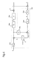
- FIG. 4 lies in the position of the steering actuator 28a, in which the sum of the commanded wheel steering angle ⁇ L and the correction steering angle ⁇ C is entered.
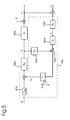
- Figure 5 shows a variant of Figure 4, in which as an input signal to the filter 38a, as in FIG. 4, the input signal of the actuator 28a, but its output signal is used becomes. This can improve the robustness of the control towards non-linear behavior of the actuator 28a can be achieved, especially in relation to saturation effects (Actuation rate limitation, etc.) of the actuator 28a.
- the filters in this example have a bandpass character.
- the bandpass character enables the control device to react only to the components of a deviation from the desired yaw behavior in the medium frequency range and to reduce its control effect after a few tenths of a second. It is assumed that the driver can normally respond appropriately to the low-frequency components of the deviation from the desired greed behavior.
- the bandpass characteristic thus ensures frequency-selective man / machine task separation.
- a linearized single-track model of the vehicle with a steered front wheel 42 and a rear wheel 44 outlined in FIG. 8 can be used, for example, to determine a suitable desired steering transmission function G n for a front-wheel steered road vehicle.
- F f and F r denote the lateral force on the front wheel 42 and rear wheel 44, CG the center of gravity of the vehicle, r the yaw rate of the vehicle, v the amount of the vehicle speed vector in the center of gravity CG, l f and l r the distance of the front or rear axle from the center of gravity CG , ⁇ f the front wheel steering angle and ⁇ the float angle between the speed vector v and the vehicle longitudinal axis in the center of gravity CG.
- c f0 and c r0 denote the nominal slip resistance at the front and rear, ⁇ the adhesion coefficient between tire and road, m the vehicle mass and J the moment of inertia of the vehicle around the vertical axis through the center of gravity CG.
- ⁇ n and K n are IMZF controller parameters that can be selected depending on various operating states or parameters (for example ⁇ , v, m, ). It is easy to see that the desired steering transfer function G n is dependent on the vehicle speed.
Landscapes
- Engineering & Computer Science (AREA)
- Transportation (AREA)
- Mechanical Engineering (AREA)
- Chemical & Material Sciences (AREA)
- Combustion & Propulsion (AREA)
- Physics & Mathematics (AREA)
- Mathematical Physics (AREA)
- Steering Control In Accordance With Driving Conditions (AREA)
Abstract
Description
- ein Betätigungsorgan zum Ansteuern eines verstellbaren Steuerelements (beispielsweise durch einen Benutzer), wobei das Betätigungsorgan mit dem Steuerelement über einen Steuerübertragungsstrang verbunden ist und das Steuerelement das Verhalten (Gieren, Nicken, Rollen, Wanken, usw.) des Fahrzeugs um die definierte Achse beeinflußt,
- einen Sensor zur Erfassung der Drehrate des Fahrzeugs um die definierte Achse,
- einen Sensor zur Erfassung eines für die Stellung des Steuerelements repräsentativen Stellsignals, und
- einen Regler, der ein Korrektursignal ermittelt durch Differenzbildung des Stellsignals mit einem theoretischen Stellsignal, das durch Filterung der erfaßten Drehrate beispielsweise mit der Inversen einer Wunschführungsübertragungsfunktion berechnet wird, und das Korrektursignal auf den Steuerübertragungsstrang zurückführt.
- ein (beispielsweise von einem Fahrer des Fahrzeugs bedienbares) über einen Lenkübertragungsstrang mit mindestens einem gelenkten Rad des Fahrzeugs verbundenes Lenkbetätigungsorgan,
- eine Gierratenerfassungseinrichtung, welche ein für die Gierrate des Fahrzeugs repräsentatives Gierratensignal bereitstellt,
- eine Radlenkwinkelerfassungseinrichtung, welche Radlenkwinkelinformationen über den Radlenkwinkel des gelenkten Rads bereitstellt, und
- eine auf das Gierratensignal und die Radlenkwinkelinformationen ansprechende und auf den Lenkübertragungsstrang einwirkende Regeleinrichtung, welche dazu eingerichtet ist, bei Auftreten unerwünschter Gierbewegungen des Fahrzeugs einen fahrerunabhängigen Lenkeingriff im Sinne einer Reduzierung dieser Gierbewegungen zu bewirken.
- Erfassen der Drehrate des Fahrzeugs um die definierte Achse,
- Erfassen eines für die Stellung des Steuerelements repräsentativen Stellsignals,
- Berechnung eines Korrektursignals durch Differenzbildung des Stellsignals mit einem theoretischen Stellsignal, das durch Filterung der erfaßten Drehrate beispielsweise mit der Inversen einer Wunschführungsübertragungsfunktion berechnet wird, und
- Rückführung des Korrektursignals auf den Steuerübertragungsstrang.
- Fig.1
- stark schematisiert ein erstes Ausführungsbeispiel der erfindungsgemäßen Lenkeinrichtung,
- Fig.2
- ebenfalls in starker Schematisierung ein zweites Ausführungsbeispiel der erfindungsgemäßen Lenkeinrichtung,
- Fig.3
- ein Signalflußbild für das Ausführungsbeispiel gemäß Fig.1,
- Fig.4
- ein Signalflußbild für das Ausführungsbeispiel gemäß Fig.2,
- Fig.5
- ein abgewandeltes Signalflußbild für das Ausführungsbeispiel gemäß Fig.2,
- Fig.6
- eine P-Kennlinie als Beispiel für einen geschwindigkeitsselektiven Ein-/Ausschaltvorgang,
- Fig.7
- den Frequenzgang eines in der erfindungsgemäßen Lenkeinrichtung verwendeten Bandpaßfilters und
- Fig.8
- schematisch ein Fahrzeugmodell als Grundlage zur Entwicklung eines IMZF-Reglers für die erfindungsgemäßen Lenkeinrichtung.


Claims (25)
- Geregelte Einrichtung zur Steuerung des dynamischen Verhaltens eines Fahrzeugs um eine definierte Achse, aufweisend:ein Betätigungsorgan zum Ansteuern eines verstellbaren Steuerelements, wobei das Betätigungsorgan mit dem Steuerelement über einen Steuerübertragungsstrang verbunden ist und das Steuerelement das Verhalten des Fahrzeugs um die definierte Achse beeinflußt,einen Sensor zur Erfassung der Drehrate des Fahrzeugs um die definierte Achse,einen Sensor zur Erfassung eines für die Stellung des Steuerelements repräsentativen Stellsignals, undeinen Regler, der ein Korrektursignal ermittelt durch Differenzbildung des Stellsignals mit einem theoretischen Stellsignal, das durch Filterung der erfaßten Drehrate berechnet wird, und das Korrektursignal auf den Steuerübertragungsstrang zurückführt.
- Einrichtung nach Anspruch 1, dadurch gekennzeichnet, daß die erfaßte Drehrate mit der Inversen einer Wunschführungsübertragungsfunktion gefiltert wird.
- Einrichtung nach Anspruch 1 oder 2, dadurch gekennzeichnet, daß in dem Regler (18; 18a) die Inverse (Gn -1 ) eines Modells (Gn ) implementiert ist, welches ein gewünschtes dynamisches Verhalten des Fahrzeugs um die vorbestimmte Achse in Abhängigkeit von der Stellung des Steuerelements beschreibt, und daß dieses Modell (Gn ) abhängig von der Fahrzeuggeschwindigkeit (v) ist.
- Einrichtung nach einem der vorhergehenden Ansprüche, dadurch gekennzeichnet, daß die Ansprechempfindlichkeit des Reglers (18; 18a) auf unerwünschte Bewegungen des Fahrzeugs
um die vorbestimmte Achse innerhalb eines an Fahrzeugstillstand anschließenden Bereichs niedriger Fahrzeuggeschwindigkeit (v) geringer ist als bei höheren Fahrzeuggeschwindigkeiten (v). - Einrichtung nach Anspruch 4, dadurch gekennzeichnet, daß die Ansprechempfindlichkeit des Reglers (18; 18a) auf unerwünschte Bewegungen des Fahrzeugs um die vorbestimmte Achse innerhalb des Bereichs niedriger Fahrzeuggeschwindigkeit zumindest annähernd null ist und im Anschluß daran allmählich ansteigt.
- Einrichtung nach einem der vorhergehenden Ansprüche, dadurch gekennzeichnet, daß der Regler (18; 18a) zur Erzielung einer Bandpaßcharakter aufweisenden Ansprechempfindlichkeit gegenüber unerwünschten Bewegungen um die vorbestimmte Achse mit einer Bandpaßfilteranordnung (34, 38; 34a, 38a) ausgeführt ist.
- Lenkeinrichtung für ein Straßenfahrzeug, umfassendein über einen Lenkübertragungsstrang (12; 12a) mit mindestens einem gelenkten Rad (14; 14a) des Fahrzeugs verbundenes Lenkbetätigungsorgan (10; 10a),eine Gierratenerfassungseinrichtung (22; 22a), welche ein für die Gierrate (r) des Fahrzeugs repräsentatives Gierratensignal bereitstellt,eine Radlenkwinkelerfassungseinrichtung (20; 20a), welche Radlenkwinkelinformationen über den Radlenkwinkel (δ) des gelenkten Rads (14; 14a) bereitstellt, undeine auf das Gierratensignal und die Radlenkwinkelinformationen ansprechende und auf den Lenkübertragungsstrang (12; 12a) einwirkende Regeleinrichtung (16; 16a), welche dazu eingerichtet ist, bei Auftreten unerwünschter Gierbewegungen des Fahrzeugs einen unabhängigen Lenkeingriff im Sinne einer Reduzierung dieser Gierbewegungen zu bewirken, dadurch gekennzeichnet, daß die Regeleinrichtung (16; 16a) einen von dem Gierratensignal (r) und den Radlenkwinkelinformationen gespeisten Regler (18; 18a) umfaßt, welcher ein für die unerwünschten Gierbewegungen repräsentatives Radlenkwinkelkorrektursignal (δC ) bereitstellt, und daß die Regeleinrichtung (16; 16a) dazu eingerichtet ist, den Lenkeingriff in Abhängigkeit von dem Radlenkwinkelkorrektursignal (δC ) zu bewirken.
- Lenkeinrichtung nach Anspruch 7, dadurch gekennzeichnet, daß in dem Regler (18; 18a) die Inverse (Gn -1 ) eines Modells (Gn ) implementiert ist, welches eine gewünschte Gierdynamik des Fahrzeugs in Abhängigkeit vom Radlenkwinkel (δ) des gelenkten Rads (14; 14a) beschreibt, und daß dieses Modell (Gn ) der Gierdynamik abhängig von der Fahrzeuggeschwindigkeit (v) ist.
- Lenkeinrichtung nach Anspruch 7 oder 8, dadurch gekennzeichnet, daß die Ansprechempfindlichkeit des Reglers (18; 18a) auf unerwünschte Gierbewegungen des Fahrzeugs innerhalb eines an Fahrzeugstillstand anschließenden Langsamfahrbereichs der Fahrzeuggeschwindigkeit (v) geringer ist als bei höheren Fahrzeuggeschwindigkeiten (v).
- Lenkeinrichtung nach Anspruch 9, dadurch gekennzeichnet, daß die Ansprechempfindlichkeit des Reglers (18; 18a) auf unerwünschte Gierbewegungen des Fahrzeugs innerhalb des Langsamfahrbereichs zumindest annähernd null ist und im Anschluß daran allmählich ansteigt.
- Lenkeinrichtung nach einem der Ansprüche 7 bis 10, dadurch gekennzeichnet, daß der Regler (18; 18a) zur Erzielung einer Bandpaßcharakter aufweisenden Ansprechempfindlichkeit gegenüber unerwünschten Fahrzeuggierbewequngen mit einer Bandpaßfilteranordnung (34, 38; 34a, 38a) ausgeführt ist.
- Lenkeinrichtung nach einem der Ansprüche 7 bis 11, dadurch gekennzeichnet, daß der Regler (18; 18a) auf Grundlage der Gierdynamik eines linearisierten Einspurmodells des Fahrzeugs (Fig.8) gebildet ist.
- Verfahren zur Regelung des dynamischen Verhaltens eines Fahrzeugs um eine definierte Achse,
wobei das Fahrzeug ein Betätigungsorgan zum Ansteuern eines verstellbaren Steuerelements aufweist, das Betätigungsorgan mit dem Steuerelement über einen Steuerübertragungsstrang verbunden ist und das Steuerelement das Verhalten des Fahrzeugs um die definierte Achse beeinflußt,
wobei die folgenden Schritte durchgeführt werden:Erfassen der Drehrate des Fahrzeugs um die definierte Achse,Erfassen eines für die Stellung des Steuerelements repräsentativen Stellsignals,Berechnung eines Korrektursignals durch Differenzbildung des Stellsignals mit einem theoretischen Stellsignal, das durch Filterung der erfaßten Drehrate berechnet wird, undRückführung des Korrektursignals auf den Steuerübertragungsstrang. - Verfahren nach Anspruch 13, dadurch gekennzeichnet, daß die Drehrate mit der Inversen einer Wunschführungsübertragungsfunktion gefiltert wird.
- Verfahren nach Anspruch 13 oder 14, dadurch gekennzeichnet, daß ein Regler (18; 18a) verwendet wird, in dem die Inverse (Gn -1 ) eines Modells (Gn ) implementiert ist, welches eine gewünschte Dynamik des Fahrzeugs um die vorbestimmte Achse in Abhängigkeit von der Stellung des Steuerelements beschreibt, wobei dieses Modell (Gn ) des dynamischen Verhaltens um die vorbestimmte Achse abhängig von der Fahrzeuggeschwindigkeit (v) ist.
- Verfahren nach einem der Ansprüche 13 bis 15, dadurch gekennzeichnet, daß ein Regler (18; 18a) verwendet wird, dessen Ansprechempfindlichkeit auf unerwünschte Bewegungen des Fahrzeugs um die vorbestimmte Achse innerhalb eines an Fahrzeugstillstand anschließenden Bereichs niedriger Fahrzeuggeschwindigkeit (v) geringer ist und bei höheren Fahrzeuggeschwindigkeiten (v) größer ist.
- Verfahren nach Anspruch 16, dadurch gekennzeichnet, daß ein Regler (18; 18a) verwendet wird, dessen Ansprechempfindlichkeit auf unerwünschte Bewegungen des Fahrzeugs um die vorbestimmte Achse innerhalb des Langsamfahrbereichs zumindest annähernd null ist und im Anschluß daran allmählich ansteigt.
- Verfahren nach einem der Ansprüche 13 bis 17, dadurch gekennzeichnet, daß ein Regler (18; 18a) verwendet wird, der zur Erzielung einer Bandpaßcharakter aufweisenden Ansprechempfindlichkeit gegenüber unerwünschten Bewegungen des Fahrzeugs um die vorbestimmte Achse mit einer Bandpaßfilteranordnung (34, 38; 34a, 38a) ausgeführt ist.
- Verfahren zum Lenken eines Straßenfahrzeugs,
welches ein über einen Lenkübertragungsstrang (12; 12a) mit mindestens einem gelenkten Rad (14; 14a) des Fahrzeugs verbundenes Lenkbetätigungsorgan (10; 10a) umfaßt, wobei bei dem Verfahren ein für die Gierrate (r) des Fahrzeugs repräsentatives Gierratensignal und Radlenkwinkelinformationen über den Radlenkwinkel (δ) des gelenkten Rads (14; 14a) bereitgestellt werden und bei Auftreten unerwünschter Gierbewegungen des Fahrzeugs ein unabhängiger Lenkeingriff auf den Lenkübertragungsstrang (12; 12a) in Abhängigkeit von dem Gierratensignal und den Radlenkwinkelinformationen im Sinne einer Reduzierung dieser unerwünschten Gierbewegungen bewirkt wird, dadurch gekennzeichnet, daß mittels eines von dem Gierratensignal und den Radlenkwinkelinformationen gespeisten Reglers (18; 18a) ein für die unerwünschten Gierbewegungen repräsentatives Radlenkwinkelkorrektursignal (δC ) ermittelt wird und der Lenkeingriff in Abhängigkeit von diesem Radlenkwinkelkorrektursignal (δ C ) bewirkt wird. - Verfahren nach Anspruch 19, dadurch gekennzeichnet, daß ein Regler (18; 18a) verwendet wird, in dem die Inverse (Gn-1) eines Modells (Gn ) implementiert ist, welches eine gewünschte Gierdynamik des Fahrzeugs in Abhängigkeit vom Radlenkwinkel (δ) des gelenkten Rads (14; 14a) beschreibt, wobei dieses Modell (Gn ) der Gierdynamik abhängig von der Fahrzeuggeschwindigkeit (v) ist.
- Verfahren nach Anspruch 19 oder 20, dadurch gekennzeichnet, daß ein Regler (18; 18a) verwendet wird, dessen Ansprechempfindlichkeit auf unerwünschte Gierbewegungen des Fahrzeugs innerhalb eines an Fahrzeugstillstand anschließenden Langsamfahrbereichs der Fahrzeuggeschwindigkeit (v) geringer ist und bei höheren Fahrzeuggeschwindigkeiten (v) größer ist.
- Verfahren nach Anspruch 21, dadurch gekennzeichnet, daß ein Regler (18; 18a) verwendet wird, dessen Ansprechempfindlichkeit auf unerwünschte Gierbewegungen des Fahrzeugs innerhalb des Langsamfahrbereichs zumindest annähernd null ist und im Anschluß daran allmählich ansteigt.
- Verfahren nach einem der Ansprüche 19 bis 22, dadurch gekennzeichnet, daß ein Regler (18; 18a) verwendet wird, der zur Erzielung einer Bandpaßcharakter aufweisenden Ansprechempfindlichkeit gegenüber unerwünschten Fahrzeuggierbewegungen mit einer Bandpaßfilteranordnung (34, 38; 34a,38a) ausgeführt ist.
- Verfahren nach einem der Ansprüche 19 bis 23, dadurch gekennzeichnet, daß ein auf Grundlage der Gierdynamik eines linearisierten Einspurmodells des Fahrzeugs (Fig.8) gebildeter Regler (18; 18a) verwendet wird.
- Computersoftwareprodukt, dadurch gekennzeichnet, daß es im in einem Rechner implementierten Zustand die Ausführung eines Verfahrens nach einem der Ansprüche 19 bis 24 ermöglicht.
Applications Claiming Priority (2)
| Application Number | Priority Date | Filing Date | Title |
|---|---|---|---|
| DE10061966 | 2000-12-13 | ||
| DE10061966A DE10061966A1 (de) | 2000-12-13 | 2000-12-13 | Regelung des dynamischen Verhaltens eines Fahrzeugs um eine definierte Achse |
Publications (3)
| Publication Number | Publication Date |
|---|---|
| EP1215103A2 true EP1215103A2 (de) | 2002-06-19 |
| EP1215103A3 EP1215103A3 (de) | 2002-08-28 |
| EP1215103B1 EP1215103B1 (de) | 2005-02-09 |
Family
ID=7666897
Family Applications (1)
| Application Number | Title | Priority Date | Filing Date |
|---|---|---|---|
| EP01129567A Expired - Lifetime EP1215103B1 (de) | 2000-12-13 | 2001-12-12 | Regelung des dynamischen Verhaltens eines Fahrzeugs um eine definierte Achse |
Country Status (2)
| Country | Link |
|---|---|
| EP (1) | EP1215103B1 (de) |
| DE (2) | DE10061966A1 (de) |
Cited By (5)
| Publication number | Priority date | Publication date | Assignee | Title |
|---|---|---|---|---|
| EP1426258A1 (de) * | 2002-11-26 | 2004-06-09 | Toyota Jidosha Kabushiki Kaisha | System zur Regelung des Verhaltens eines Kraftfahrzeuges |
| WO2004089725A1 (en) * | 2003-04-09 | 2004-10-21 | Trw Limited | Rack force disturbance rejection |
| EP1849682A1 (de) * | 2006-04-28 | 2007-10-31 | ZF-Lenksysteme GmbH | Verfahren zur Lenkungsregelung |
| FR2906517A1 (fr) * | 2006-10-02 | 2008-04-04 | Renault Sas | Procede et systeme de controle d'un vehicule equipe d'un systeme de freinage pilote. |
| FR2917363A1 (fr) * | 2007-06-13 | 2008-12-19 | Renault Sas | Systeme et procede de commande du braquage de roues directrices d'un vehicule automobile en situation de freinage avec adherence asymetrique. |
Families Citing this family (8)
| Publication number | Priority date | Publication date | Assignee | Title |
|---|---|---|---|---|
| DE10316413B4 (de) * | 2003-04-10 | 2011-02-03 | Man Nutzfahrzeuge Ag | Verfahren und Vorrichtung zur Spurführung eines Fahrzeugs, insbesondere Nutzfahrzeugs |
| DE10357254B4 (de) * | 2003-12-08 | 2014-11-13 | Knorr-Bremse Systeme für Nutzfahrzeuge GmbH | Verfahren zum Kompensieren des durch eine Änderung des Abrollverhaltens eines Laufrades eines Fahrzeugs hervorgerufenen Giermoments |
| KR100656328B1 (ko) * | 2004-10-13 | 2006-12-13 | 닛산 지도우샤 가부시키가이샤 | 조향 가능한 차량을 위한 조향 장치 |
| DE102004051759A1 (de) * | 2004-10-23 | 2006-04-27 | Daimlerchrysler Ag | Integration eines Fahrzeugmodells mit Echtzeitaktualisierung |
| JP4179348B2 (ja) * | 2006-06-22 | 2008-11-12 | トヨタ自動車株式会社 | 走行装置 |
| DE102017200431A1 (de) * | 2017-01-12 | 2018-07-12 | Volkswagen Aktiengesellschaft | Lenkunterstützungsverfahren, Lenkunterstützungssystem und Fahrzeug |
| DE102020109878A1 (de) | 2020-04-08 | 2021-10-14 | Technische Universität Darmstadt | Vorrichtung zur automatischen Ermittlung eines kritischen Zustands für ein Fahrzeug |
| US11052940B1 (en) | 2021-03-12 | 2021-07-06 | Canoo Technologies Inc. | Steer-by-wire systems and methods of operating thereof in vehicles |
Family Cites Families (17)
| Publication number | Priority date | Publication date | Assignee | Title |
|---|---|---|---|---|
| JPH0725320B2 (ja) * | 1986-10-13 | 1995-03-22 | 日産自動車株式会社 | 車両用実舵角制御装置 |
| FR2608545B1 (fr) * | 1986-12-19 | 1990-08-31 | Peugeot | Dispositif de correction de l'angle d'attitude d'un vehicule automobile |
| DE4028320A1 (de) * | 1990-09-06 | 1992-03-12 | Deutsche Forsch Luft Raumfahrt | Verfahren zum lenken von strassenfahrzeugen mit vorder- und hinterradlenkung |
| JPH04133860A (ja) * | 1990-09-25 | 1992-05-07 | Honda Motor Co Ltd | 車輌用操舵装置の制御方法 |
| DE4133238C2 (de) * | 1991-10-05 | 2001-09-27 | Bosch Gmbh Robert | System zur Erlangung eines die Fahrbahnoberfläche repräsentierenden Signals |
| DE4226746C1 (de) * | 1992-08-13 | 1993-10-07 | Daimler Benz Ag | Verfahren zur Bestimmung eines fahrsituationsabhängigen Lenkwinkels |
| DE4307420C1 (de) * | 1993-03-09 | 1994-04-28 | Deutsche Forsch Luft Raumfahrt | Verfahren zum Lenken eines Straßenfahrzeugs mit Vorderradlenkung |
| US5703775A (en) * | 1993-09-16 | 1997-12-30 | Honda Giken Kogyo Kabushiki Kaisha | Vehicle steering control system |
| DE19515050A1 (de) * | 1994-11-25 | 1996-05-30 | Teves Gmbh Alfred | Verfahren zur Fahrstabilitätsregelschaltung mit Steuerung über Druckgradienten |
| JP3493806B2 (ja) * | 1995-04-21 | 2004-02-03 | 日本精工株式会社 | 電動パワ−ステアリング装置の制御装置 |
| US5696681A (en) * | 1995-06-05 | 1997-12-09 | Ford Global Technologies, Inc. | Brake steer vehicle dynamics control intervention |
| DE19600734C2 (de) * | 1996-01-11 | 2003-03-06 | Zahnradfabrik Friedrichshafen | Verfahren zur Steuerung von Aggregaten und/oder Systemen eines Kraftfahrzeugs |
| DE19650691C2 (de) * | 1996-12-07 | 1998-10-29 | Deutsch Zentr Luft & Raumfahrt | Verfahren zur Lenkunterstützung eines Fahrers eines Straßenfahrzeugs |
| DE19751227B4 (de) * | 1997-03-22 | 2009-09-17 | Robert Bosch Gmbh | Verfahren und Vorrichtung zum Betrieb eines Lenksystems für ein Kraftfahrzeug |
| DE19750585A1 (de) * | 1997-11-17 | 1999-06-02 | Deutsch Zentr Luft & Raumfahrt | Aktuator zum Korrigieren eines über das Lenkrad eines Fahrzeugs an die Räder einer gelenkten Fahrzeugachse eingegebenen Lenkwinkels |
| DE19812238A1 (de) * | 1998-03-20 | 1999-09-23 | Daimler Chrysler Ag | Verfahren zur Regelung des Gierverhaltens von Fahrzeugen |
| DE19851978A1 (de) * | 1998-11-11 | 2000-05-25 | Daimler Chrysler Ag | Verfahren zur Regelung der Querdynamik eines Fahrzeuges mit Vorderachs-Lenkung |
-
2000
- 2000-12-13 DE DE10061966A patent/DE10061966A1/de not_active Withdrawn
-
2001
- 2001-12-12 DE DE50105296T patent/DE50105296D1/de not_active Expired - Lifetime
- 2001-12-12 EP EP01129567A patent/EP1215103B1/de not_active Expired - Lifetime
Cited By (10)
| Publication number | Priority date | Publication date | Assignee | Title |
|---|---|---|---|---|
| EP1426258A1 (de) * | 2002-11-26 | 2004-06-09 | Toyota Jidosha Kabushiki Kaisha | System zur Regelung des Verhaltens eines Kraftfahrzeuges |
| US7142969B2 (en) | 2002-11-26 | 2006-11-28 | Toyota Jidosha Kabushiki Kaisha | Behavior control system for vehicle |
| WO2004089725A1 (en) * | 2003-04-09 | 2004-10-21 | Trw Limited | Rack force disturbance rejection |
| US7273127B2 (en) | 2003-04-09 | 2007-09-25 | Trw Limited | Rack force disturbance rejection |
| EP1849682A1 (de) * | 2006-04-28 | 2007-10-31 | ZF-Lenksysteme GmbH | Verfahren zur Lenkungsregelung |
| FR2906517A1 (fr) * | 2006-10-02 | 2008-04-04 | Renault Sas | Procede et systeme de controle d'un vehicule equipe d'un systeme de freinage pilote. |
| WO2008040909A3 (fr) * | 2006-10-02 | 2008-05-22 | Renault Sa | Procède et système de contrôle d'un véhicule équipe d'un système de freinage pilote |
| FR2917363A1 (fr) * | 2007-06-13 | 2008-12-19 | Renault Sas | Systeme et procede de commande du braquage de roues directrices d'un vehicule automobile en situation de freinage avec adherence asymetrique. |
| WO2008155501A3 (fr) * | 2007-06-13 | 2009-02-12 | Renault Sa | Systeme et procede de commande du braquage de roues directrices d'un vehicule automobile en situation de freinage avec adherence asymetrique |
| JP2010528936A (ja) * | 2007-06-13 | 2010-08-26 | ルノー・エス・アー・エス | 非対称粘着を伴う制動状態における自動車の操舵輪の転舵を制御するシステム及び方法 |
Also Published As
| Publication number | Publication date |
|---|---|
| EP1215103B1 (de) | 2005-02-09 |
| DE10061966A1 (de) | 2002-06-27 |
| EP1215103A3 (de) | 2002-08-28 |
| DE50105296D1 (de) | 2005-03-17 |
Similar Documents
| Publication | Publication Date | Title |
|---|---|---|
| EP1000838B1 (de) | Verfahren zur Regelung der Querdynamik eines Fahrzeuges mit Vorderachs-Lenkung | |
| DE60314199T2 (de) | System und Verfahren für die Anwendung der Absicht einer Fahrzeugbedienungsperson zum Abstimmen des Fahrzeugsteuerungssystems | |
| DE60202086T3 (de) | Überrollstabilitätssteuerung für ein Kraftfahrzeug | |
| EP1807300B1 (de) | Verfahren und vorrichtung zum unterstützen eines fahrzeugbedieners beim stabilisieren eines fahrzeugs | |
| EP2164746B1 (de) | Lenkvorrichtung zum einstellen eines radeinschlagwinkels | |
| EP1521695B1 (de) | Verfahren zum erhöhen der stabilität eines fahrzeugs | |
| EP0846610B1 (de) | Verfahren zur Lenkunterstützung eines Fahrers eines Strassenfahrzeugs | |
| DE10348738B4 (de) | Steuerungssystem für ein Kraftfahrzeug und Verfahren zum Steuern eines Kraftfahrzeugs | |
| EP1758774B1 (de) | Verfahren und einrichtung zum stabilisieren eines fahrzeugs | |
| DE4028320C2 (de) | ||
| EP3328693B1 (de) | Verfahren zur fahrerunterstützung bei wasserglätte auf einem fahrbahnuntergrund | |
| DE10248343A1 (de) | Verfahren zur Ansteuerung eines Betätigungskraftsimulators einer Fahrzeuglenkung | |
| DE102013216931A1 (de) | Ausweichassistent für Kraftfahrzeuge | |
| EP1215103B1 (de) | Regelung des dynamischen Verhaltens eines Fahrzeugs um eine definierte Achse | |
| EP1890920B1 (de) | Fahrzustandsangepasste, auf lenkeingriffen basierende fahrdynamikregelung | |
| WO2017137228A1 (de) | Verfahren zur beeinflussung der fahrtrichtung von kraftfahrzeugen | |
| WO2008046586A2 (de) | Verfahren zur regelung der gierrate eines kraftfahrzeuges | |
| DE60213215T2 (de) | Fahrzeuglenksystem mit Übersteuerkorrektur Assistent | |
| DE60214637T2 (de) | Verfahren und Vorrichtung mit dynamischer Vorwärtssteuerung zur integrierten Lenk- und Bremssteuerung eines Kraftfahrzeugs | |
| DE102016204512A1 (de) | Vorrichtung und Verfahren zur Stabilitätsregelung eines Fahrzeugs bei Verlassen einer Fahrbahn | |
| EP2052884A2 (de) | Verfahren und System zur Beeinflussung der Bewegung eines in seinen Bewegungsabläufen steuerbaren oder regelbaren Fahrzeugaufbaus eines Kraftfahrzeuges und Fahrzeug | |
| EP1638825A1 (de) | Stabilisierungsvorrichtung, damit ausgestattetes fahrzeug und stabilisierungsverfahren | |
| DE102021205561A1 (de) | Verfahren und System zur Steuerung eines Fahrzeugs | |
| EP1336548B1 (de) | Gierdämpfung bei der Fahrzeuglenkung | |
| EP4169785B1 (de) | Verfahren zum sicheren beenden einer bankettfahrt eines kraftfahrzeugs |
Legal Events
| Date | Code | Title | Description |
|---|---|---|---|
| PUAI | Public reference made under article 153(3) epc to a published international application that has entered the european phase |
Free format text: ORIGINAL CODE: 0009012 |
|
| AK | Designated contracting states |
Kind code of ref document: A2 Designated state(s): AT BE CH CY DE DK ES FI FR GB GR IE IT LI LU MC NL PT SE TR |
|
| AX | Request for extension of the european patent |
Free format text: AL;LT;LV;MK;RO;SI |
|
| PUAL | Search report despatched |
Free format text: ORIGINAL CODE: 0009013 |
|
| AK | Designated contracting states |
Kind code of ref document: A3 Designated state(s): AT BE CH CY DE DK ES FI FR GB GR IE IT LI LU MC NL PT SE TR |
|
| AX | Request for extension of the european patent |
Free format text: AL;LT;LV;MK;RO;SI |
|
| 17P | Request for examination filed |
Effective date: 20030122 |
|
| AKX | Designation fees paid |
Designated state(s): DE FR GB IT SE |
|
| 17Q | First examination report despatched |
Effective date: 20030414 |
|
| GRAP | Despatch of communication of intention to grant a patent |
Free format text: ORIGINAL CODE: EPIDOSNIGR1 |
|
| GRAS | Grant fee paid |
Free format text: ORIGINAL CODE: EPIDOSNIGR3 |
|
| GRAA | (expected) grant |
Free format text: ORIGINAL CODE: 0009210 |
|
| AK | Designated contracting states |
Kind code of ref document: B1 Designated state(s): DE FR GB IT SE |
|
| REG | Reference to a national code |
Ref country code: GB Ref legal event code: FG4D Free format text: NOT ENGLISH |
|
| GBT | Gb: translation of ep patent filed (gb section 77(6)(a)/1977) |
Effective date: 20050209 |
|
| REG | Reference to a national code |
Ref country code: IE Ref legal event code: FG4D Free format text: GERMAN |
|
| REF | Corresponds to: |
Ref document number: 50105296 Country of ref document: DE Date of ref document: 20050317 Kind code of ref document: P |
|
| REG | Reference to a national code |
Ref country code: SE Ref legal event code: TRGR |
|
| PLBE | No opposition filed within time limit |
Free format text: ORIGINAL CODE: 0009261 |
|
| STAA | Information on the status of an ep patent application or granted ep patent |
Free format text: STATUS: NO OPPOSITION FILED WITHIN TIME LIMIT |
|
| ET | Fr: translation filed | ||
| 26N | No opposition filed |
Effective date: 20051110 |
|
| PGFP | Annual fee paid to national office [announced via postgrant information from national office to epo] |
Ref country code: FR Payment date: 20101203 Year of fee payment: 10 |
|
| PGFP | Annual fee paid to national office [announced via postgrant information from national office to epo] |
Ref country code: IT Payment date: 20101215 Year of fee payment: 10 Ref country code: GB Payment date: 20101123 Year of fee payment: 10 Ref country code: SE Payment date: 20101122 Year of fee payment: 10 |
|
| PGFP | Annual fee paid to national office [announced via postgrant information from national office to epo] |
Ref country code: DE Payment date: 20101230 Year of fee payment: 10 |
|
| REG | Reference to a national code |
Ref country code: SE Ref legal event code: EUG |
|
| GBPC | Gb: european patent ceased through non-payment of renewal fee |
Effective date: 20111212 |
|
| REG | Reference to a national code |
Ref country code: FR Ref legal event code: ST Effective date: 20120831 |
|
| REG | Reference to a national code |
Ref country code: DE Ref legal event code: R119 Ref document number: 50105296 Country of ref document: DE Effective date: 20120703 |
|
| PG25 | Lapsed in a contracting state [announced via postgrant information from national office to epo] |
Ref country code: GB Free format text: LAPSE BECAUSE OF NON-PAYMENT OF DUE FEES Effective date: 20111212 Ref country code: SE Free format text: LAPSE BECAUSE OF NON-PAYMENT OF DUE FEES Effective date: 20111213 Ref country code: DE Free format text: LAPSE BECAUSE OF NON-PAYMENT OF DUE FEES Effective date: 20120703 |
|
| PG25 | Lapsed in a contracting state [announced via postgrant information from national office to epo] |
Ref country code: IT Free format text: LAPSE BECAUSE OF NON-PAYMENT OF DUE FEES Effective date: 20111212 |
|
| PG25 | Lapsed in a contracting state [announced via postgrant information from national office to epo] |
Ref country code: FR Free format text: LAPSE BECAUSE OF NON-PAYMENT OF DUE FEES Effective date: 20120102 |