EP1215073A2 - Verfahren und Vorrichtung zur Regelung eines Antriebs für ein Schienenfahrzeug - Google Patents
Verfahren und Vorrichtung zur Regelung eines Antriebs für ein Schienenfahrzeug Download PDFInfo
- Publication number
- EP1215073A2 EP1215073A2 EP01129677A EP01129677A EP1215073A2 EP 1215073 A2 EP1215073 A2 EP 1215073A2 EP 01129677 A EP01129677 A EP 01129677A EP 01129677 A EP01129677 A EP 01129677A EP 1215073 A2 EP1215073 A2 EP 1215073A2
- Authority
- EP
- European Patent Office
- Prior art keywords
- value
- frequency
- setpoint
- target
- actual
- Prior art date
- Legal status (The legal status is an assumption and is not a legal conclusion. Google has not performed a legal analysis and makes no representation as to the accuracy of the status listed.)
- Granted
Links
- 238000000034 method Methods 0.000 title claims abstract description 20
- 230000004913 activation Effects 0.000 claims description 29
- 238000001514 detection method Methods 0.000 claims description 17
- 230000001276 controlling effect Effects 0.000 description 8
- 230000001105 regulatory effect Effects 0.000 description 4
- 230000006872 improvement Effects 0.000 description 2
- 238000005259 measurement Methods 0.000 description 2
- 230000015572 biosynthetic process Effects 0.000 description 1
- 230000007423 decrease Effects 0.000 description 1
- 230000003247 decreasing effect Effects 0.000 description 1
- 230000001419 dependent effect Effects 0.000 description 1
- 238000011161 development Methods 0.000 description 1
- 230000018109 developmental process Effects 0.000 description 1
- 238000001914 filtration Methods 0.000 description 1
- 230000009467 reduction Effects 0.000 description 1
- 230000000630 rising effect Effects 0.000 description 1
- 230000007704 transition Effects 0.000 description 1
Images

Classifications
-
- B—PERFORMING OPERATIONS; TRANSPORTING
- B60—VEHICLES IN GENERAL
- B60L—PROPULSION OF ELECTRICALLY-PROPELLED VEHICLES; SUPPLYING ELECTRIC POWER FOR AUXILIARY EQUIPMENT OF ELECTRICALLY-PROPELLED VEHICLES; ELECTRODYNAMIC BRAKE SYSTEMS FOR VEHICLES IN GENERAL; MAGNETIC SUSPENSION OR LEVITATION FOR VEHICLES; MONITORING OPERATING VARIABLES OF ELECTRICALLY-PROPELLED VEHICLES; ELECTRIC SAFETY DEVICES FOR ELECTRICALLY-PROPELLED VEHICLES
- B60L3/00—Electric devices on electrically-propelled vehicles for safety purposes; Monitoring operating variables, e.g. speed, deceleration or energy consumption
- B60L3/10—Indicating wheel slip ; Correction of wheel slip
-
- B—PERFORMING OPERATIONS; TRANSPORTING
- B60—VEHICLES IN GENERAL
- B60L—PROPULSION OF ELECTRICALLY-PROPELLED VEHICLES; SUPPLYING ELECTRIC POWER FOR AUXILIARY EQUIPMENT OF ELECTRICALLY-PROPELLED VEHICLES; ELECTRODYNAMIC BRAKE SYSTEMS FOR VEHICLES IN GENERAL; MAGNETIC SUSPENSION OR LEVITATION FOR VEHICLES; MONITORING OPERATING VARIABLES OF ELECTRICALLY-PROPELLED VEHICLES; ELECTRIC SAFETY DEVICES FOR ELECTRICALLY-PROPELLED VEHICLES
- B60L2200/00—Type of vehicles
- B60L2200/26—Rail vehicles
Definitions
- the invention relates to the field of drive technology. It is based on a procedure and a device for controlling a drive for a rail vehicle according to the preamble of the independent claims.
- a traction control unit used today which is common today, generates at the output an idle frequency reference. Furthermore, a declining working characteristic generated, which varies in its slope by parameter settings can be.
- the characteristic curve generator generates the working characteristic curve from an actual pulling force value, where the actual pulling force value is estimated from an engine observer and is derived from the actual torque value which correlates with the actual tractive force.
- the working characteristic is a map of a typical speed-torque characteristic of an asynchronous machine.
- a characteristic curve stand frequency setpoint is used as the output variable of the characteristic curve generator output from the idle stand frequency reference of the traction control unit is subtracted. This subtraction ensures that a stator frequency setpoint is generated, which is given to the stator frequency control unit, the switching command signals outputs to a drive converter feeding the drive.
- the object of the present invention is therefore a method for controlling a drive to be specified for a rail vehicle, by means of which an optimal and stable actual tractive force value is achieved with different frictional connections between wheels and rails, and to specify a device with which the method is carried out.
- an idle stator frequency setpoint is made from a a traction control unit educated.
- the current pulling force actual value becomes a characteristic stand frequency setpoint formed by a curve generator and by subtracting the Characteristic stator frequency setpoint from the idle stator frequency setpoint is a control stator frequency setpoint generated.
- This control stator frequency setpoint is then called Specify the stator frequency setpoint of a stator frequency control unit.
- Specify the stator frequency setpoint of a stator frequency control unit is a controller frequency value from a plurality of controller frequency values formed as Idle stator frequency setpoint depending on the size of the traction setpoint with regard to of the actual pulling force value.
- the device according to the invention for controlling a drive for a rail vehicle has a motor control unit designed as a stator frequency control unit, a Traction control unit and a characteristic curve generator, wherein the traction control unit comprises a state detection unit which contains the current actual pulling force value, the pulling force setpoint, an axle speed value and a vehicle speed value are supplied are.
- the state detection unit is equipped with a first Connection device connected, wherein the state detection unit, the first connection device actuated by a first intrusion signal.
- the first intrusion device performs the actuation by the state detection unit by means of the first activation signal advantageously such that a controller frequency value is formed from a plurality of Controller frequency values as idle frequency reference depending on the size of the tensile force setpoint with respect to the actual tensile force value.
- a device is advantageously formed, which due to its simple and with few elements using only discrete components and can also be implemented, for example, in a digital microprocessor. she thus represents a simple and inexpensive solution that can also be implemented variably and can be adapted to various drives.
- 1 shows an embodiment according to the invention of the device for controlling a Drive for a rail vehicle.
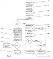
- 2 is a flowchart of the inventive Method for controlling a drive for a rail vehicle shown.
- an idle stand frequency setpoint f LS should be made from a tractive force setpoint F Z, should, for example , which can be preselected by a vehicle driver , and a current actual tractive force value F Z, is in a traction control unit provided for this purpose 11 formed.
- This formation of the idle stator frequency setpoint f LS should be described in the following.
- the actual tractive force value F Z required to form the idle stator frequency setpoint f LS, target is obtained in a motor control unit designed as a stator frequency control unit 10 from an actual torque value M ist , which is estimated by a motor observer and correlates to the actual tractive force value F Z, (S2).
- a characteristic curve stand frequency setpoint f KS should be formed from the actual tractive force value F Z, is formed in a characteristic curve generator 3 provided by filtering the actual tensile force value F Z, is formed (S3).
- the characteristic curve generator 3 has the task of generating a decreasing working characteristic curve, the working characteristic curve being an image of a typical speed-torque characteristic of an asynchronous machine.
- the output variable of the characteristic curve generator is the characteristic curve stand frequency setpoint f KS, target , which corresponds to this working characteristic curve.
- a control stator frequency setpoint f RS should be generated by subtracting the characteristic stator frequency setpoint f KS, should from the idle stator frequency setpoint f LS, should (S4).
- This control stator frequency setpoint f RS should be specified by the stator frequency control unit 10 as stator frequency setpoint f S, should (S5), which outputs switching command signals to a drive converter provided for supplying the drive.
- a controller frequency value f LZOS should , f LZRS, should be formed from a plurality of controller frequency values f LZOS, should , f LZRS should , especially a first one controller frequency value f LZRS should or a second regulator frequency value f LZOS should f as idle stator frequency value LS, should a function of the magnitude of the tractive force target value F Z, should with respect to the Switzerlandkraftistives F Z is switched.
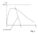
- This differentiated connection ensures that the working characteristic curve can be shifted on a typical traction characteristic curve shown in FIG.
- the first controller frequency value f LZRS should be formed as the output variable of a traction controller 6 from the actual tension value F Z ist and the desired tension value F Z, should (S6.1).
- the actual control value F Z, and an axis speed value v A of the asynchronous machine of the drive are used to form the second controller frequency value f LZOS, as the output variable of a traction optimizer 5.
- the first controller frequency value f LZRS intended as the idle stand frequency setpoint f LS, should be applied in a further method step (S6.3).
- this condition corresponds to the region of the rising branch of the adhesion curve for small values of a differential speed ⁇ v, which is defined as the difference between the axle speed value v A and a vehicle speed value v F.
- the area of the traction characteristic is decisive for the traction characteristic with a continuous improvement of the rail condition, ie if the friction coefficient between wheels increases.
- the first controller frequency value f LZRS intended as the idle stator frequency setpoint f LS, intended , which is formed in the traction controller 6 provided for this purpose, is applied to this area of the adhesion characteristic. Since the tension controller 6 which is preferably a proportional-integral characteristic which particularly effectively working in this field by a sufficiently large loop bandwidth, the Glaskraftistwert F Z can be very quickly and without significant vibrations to the predetermined tensile force desired value F Z, is to be corrected , so that a stable pulling force actual value F Z can be achieved. By avoiding significant vibrations in the actual pulling force value F Z, mechanical loads on the mechanical units and wear on wheels and rails are advantageously reduced.
- the second controller frequency value f LZOS which is in already described from the actual tractive force value F Z, and the axle speed value v A is formed as the output variable of the tractive force optimizer 5, as the idle stand frequency target value f LS, is to be applied .
- this condition corresponds to the range of the falling branch of the adhesion curve following the adhesion maximum for large values of the differential speed ⁇ v. If the rail condition deteriorates, ie if the coefficient of friction between the wheels and the rail decreases, this area of the traction characteristic is relevant for the traction characteristic.
- the second controller frequency value f LZOS which is applied as the idle stator frequency setpoint f LS, should be applied to this area of the adhesion characteristic , should , as explained above, be formed in the tractive force optimizer 5 provided for this purpose.
- the tensile force optimizer 5 shifts the working characteristic in such a way that the working point is set and stabilized close to the maximum traction. This setting of the operating point advantageously achieves the almost maximum possible actual pulling force value F Z, even in poor rail conditions, without the rail and / or the wheels being excessively worn and without mechanical vibrations putting a heavy load on the mechanical units.
- stator frequency limitation setpoint f BS formed is intended to be used as the stator frequency setpoint f S and is to be transmitted to the stator frequency control unit 10 during a preselected activation time t Auf instead of the control stand frequency setpoint f RS, should be given (S8).
- the control stand frequency setpoint f RS should be specified as the stator frequency setpoint f S, set to the stator frequency control unit 10 (S9).
- either the second controller frequency value f LZOS is to be used as the idle stand frequency setpoint f LS, is to be applied (S10) or, in the event that the axle speed value v A is lower than the vehicle speed value v F , the first controller frequency value f LZRS is to be used as the idle stand frequency setpoint f LS, should be activated (S11).
- the working point near the maximum adhesion is set by means of the tensile force optimizer 5 or the actual tensile force value F Z is very fast and without significant vibrations to the predetermined tensile force setpoint F Z, should corrected.
- the drive has a drive motor designed as an asynchronous machine, which is not shown in FIG. 1 for the sake of clarity.
- the device comprises a motor control unit designed as a stator frequency control unit 10 and a traction control unit 11, which is used to form the idle stator frequency setpoint f LS .
- the characteristic curve generator 3 already mentioned is provided.
- the traction control unit 11 and the characteristic curve generator are connected to an adder 9, which, by subtracting the characteristic stator frequency setpoint f KS, is from the idle stator frequency setpoint f LS, is the control stator frequency setpoint f RS, is intended and, according to FIG. 1 , is the stator frequency control unit 10 as Stator frequency setpoint f S, should be specified.
- the traction control unit 11 a state detection unit 7, which is the current Switzerlandkraftistwert F Z, the tensile force desired value F Z, should the Achs mecanicswert v A and the vehicle speed value V F are fed, wherein the state detection unit 7 with a first Aufschalt gifted 4 is connected, which is actuated by the status recognition unit 7 by a first intrusion signal sel 1 , which is output by the status recognition unit 7.
- the actual pulling force value F Z, ist is derived in the stator frequency control unit 10 from an actual torque value M ist , which is estimated by a motor observer and correlates with the actual pulling force value F Z, and is formed by a rescaler 1 by multiplication by a factor k.
- a conventional sensor which is not shown in FIG. 1 for the sake of clarity, provides the axis speed value v A.
- the vehicle speed value V F is determined by a common radar measurement, axis measurement or by a vehicle speed observer, with the provision of the vehicle speed value V F being shown exclusively in FIG. 1.
- An input of the first activation device 4 is also connected to the traction controller 6, which is used to regulate the actual tractive force value F Z to the desired tractive force value F Z, shall .
- the tension controller 6 is to the tensile force desired value F Z should Switzerlandkraftistwert and F Z is supplied, wherein the first controller frequency value f LZRS to, the output of tension controller 6.
- the tensile force optimizer 5 is connected to a further input of the override device 4. If the rail conditions deteriorate, the tensile force optimizer 5 sets the operating point on the traction characteristic shown in FIG. 3 in such a way that the almost maximum possible actual pull force value F Z is reached if the rail conditions deteriorate, without the rail and / or the wheels closing are heavily worn and without mechanical vibrations putting a heavy load on the mechanical units.
- the tractive force optimizer 5 is supplied with the actual tractive force value F Z, and the axle speed value v A , the second controller frequency value f LZOS, should be the output variable of the tractive force optimizer 5.
- the first override device 4 is actuated by the first override signal sel 1 from the status detection unit 7.
- the status recognition unit 7 first evaluates the quantities supplied. For example, if the tensile force desired value F Z, should be less than the Switzerlandkraftistwert F Z, the Intrusion is sel 1 is output such that the first Aufschalt issued 4 f the first controller frequency value LZRS should, as already described, as an idling stator frequency value f LS, should alsschaltet , If, on the other hand, the tractive force setpoint F Z is greater than the actual tractive force value F Z and the axle speed value v A is greater than the vehicle speed value v F , the activation signal sel 1 is output in such a way that the first activation device 4 should have the second controller frequency value f LZOS as idle frequency reference f LS, should be activated. Furthermore, the adder 9 is connected to the output of the first switching device 4 for supplying the idle frequency reference f LS, Soll.
- the status detection unit 7 is connected according to the invention to a second activation device 8, which is activated by the status detection unit 7 by a second activation signal sel 2 , which is output by the status detection unit 7.
- An input of the second switching device 8 is also connected to the adder 9 for supplying the control stand frequency setpoint f RS, Soll.
- the second activation signal sel 2 is output by the state detection unit 7 in such a way that the second activation device 8 activates the control stand frequency setpoint f RS, should act as the stator frequency setpoint f S, should, and thus the control stand frequency setpoint f RS, should be the stator frequency setpoint f S, should be the stator frequency control unit 10, which is connected to the output of the second activation device 8.
- Another input of the second activation device 8 is connected to the limiting device 2 for supplying the stator frequency limiting setpoint f BS, should .
- the limiting device 2 is supplied to form the stator frequency limiting setpoint f BS, the actual tractive force value F Z, and the axle speed value v A. If the actual pulling force value F Z is greater than the predetermined maximum pulling force value F Zmax, the activation signal sel 2 is output by the status detection unit 7 for the preselected activation time t Auf in such a way that the second activation device 8 uses the stator frequency limiting setpoint f BS formed, as the stator frequency setpoint f S should alsschaltet Lock on during t on and thus, as already described, the stator frequency control unit 10, the stator frequency f BS limit setpoint, to f as a stator frequency value S is to purports.
- the device for controlling a drive for a rail vehicle implemented in at least one digital microprocessor, not shown in FIG. 1 are, so that it is advantageous to dispense with discrete components and an adjustment the device on drive motors of various applications is facilitated and can therefore be carried out easily.
- the present invention discloses a method for regulating a drive for a rail vehicle, which forms an idle stator frequency setpoint f LS, from a preselectable tensile force setpoint F Z, and a current tractive force actual value F Z, is formed by a traction control unit and also a characteristic stator frequency setpoint f KS , to from the current Switzerlandkraftistwert F Z is represented by a characteristic curve generator.
- a control stator frequency value f RS should, by subtracting the characteristic curve stator frequency value f KS, should the idle stator frequency value f LS, is to generate and control stator frequency value f RS, intended as a stator frequency value f S, is to set to the stator frequency control unit, wherein a controller frequency value f LZOS, soll; f LZRS, should from a plurality of controller frequency values f LZOS, should ; f LZRS, is to be used as the idle stand frequency setpoint f LS, is to be dependent on the size of the tractive force setpoint F Z, is to be applied with respect to the actual tractive force value F Z, is . Furthermore, a device for controlling a drive for a rail vehicle is specified.
Landscapes
- Engineering & Computer Science (AREA)
- Life Sciences & Earth Sciences (AREA)
- Sustainable Development (AREA)
- Sustainable Energy (AREA)
- Power Engineering (AREA)
- Transportation (AREA)
- Mechanical Engineering (AREA)
- Electric Propulsion And Braking For Vehicles (AREA)
- Hybrid Electric Vehicles (AREA)
- Machines For Laying And Maintaining Railways (AREA)
Abstract
Description
- Fig. 1
- eine Ausführungsform einer erfindungsgemässen Vorrichtung zur Regelung eines Antriebs für ein Schienenfahrzeug,
- Fig. 2
- ein Ablaufdiagramm eines erfindungsgemässen Verfahrens zur Regelung eines Antriebs für ein Schienenfahrzeug und
- Fig. 3
- eine typische Kraftschlusskennlinie mit einer gebildeten Antriebskennlinie.
Claims (10)
- Verfahren zur Regelung eines Antriebs für ein Schienenfahrzeug, der mindestens einen als Asynchronmaschine ausgebildeten Antriebsmotor aufweist, mit den Schritten
(S1) Bilden eines Leerlaufständerfrequenzsollwertes (fLS,soll) aus einem vorwählbaren Zugkraftsollwert (FZ,soll) und einem aktuellen Zugkraftistwert (FZ,ist) durch eine Traktionsregelungseinheit (11), wobei
(S2) der Zugkraftistwert (FZ,ist) in einer als Ständerfrequenzregelungseinheit (10) ausgebildeten Motorregelungseinheit aus einem dem Zugkraftistwert (FZ,ist) entsprechenden Drehmomentistwert (Mist) abgeleitet wird,
(S3) Bilden eines Kennlinienständerfrequenzsollwertes (fKS, soll) aus dem aktuellen Zugkraftistwert (FZ,ist) durch einen Kennlinienbildner (3),
(S4) Erzeugen eines Regelungsständerfrequenzsollwertes (fRS, soll) durch Subtraktion des Kennlinienständerfrequenzsollwertes (fKS, soll) vom Leerlaufständerfrequenzsollwert (fLS, soll)
(S5) Vorgeben des Regelungsständerfrequenzsollwertes (fRS, soll) als Ständerfrequenzsollwert (fS, soll) an die Ständerfrequenzregelungseinheit (10), gekennzeichnet durch den weiteren Schritt
(S6) Aufschalten eines Reglerfrequenzwertes (fLZOS, soll; fLZRS, soll) aus einer Mehrzahl von gebildeten Reglerfrequenzwerten (fLZOS, soll; fLZRS, soll) als Leerlaufständerfrequenzsollwert (fLS, soll) in Abhängigkeit von der Grösse des Zugkraftsollwertes (FZ,soll) bezüglich des Zugkraftistwertes (FZ,ist). - Verfahren nach Anspruch 1, gekennzeichnet durch die weiteren Schritte
(S6.1) Bilden eines ersten Reglerfrequenzwertes (fLZRS, soll) aus dem Zugkraftsollwert (FZ,soll) und dem Zugkraftistwert (FZ,ist) als Ausgangsgrösse eines als Proportional-Integral-Regler ausgeführten Zugkraftreglers (6),
(S6.2) Bilden eines zweiten Reglerfrequenzwertes (fLZOS, soll) aus dem Zugkraftistwert (FZ,ist) und einem Achsgeschwindigkeitswert (vA) des Antriebs als Ausgangsgrösse eines Zugkraftoptimierers (5),
(S6.3) Aufschalten des ersten Reglerfrequenzwertes (fLZRS, soll) als Leerlaufständerfrequenzsollwert (fLS, soll) im Falle, dass der Zugkraftsollwert (FZ,soll) kleiner ist als der Zugkraftistwert (FZ,ist)
oder
(S6.4) Aufschalten des zweiten Reglerfrequenzwertes (fLZOS, soll) als Leerlaufständerfrequenzsollwert (fLS, soll) im Falle, dass der Zugkraftsollwert (FZ,soll) grösser ist als der Zugkraftistwert (FZ,ist) und dass der Achsgeschwindigkeitswert (vA) wesentlich grösser ist als ein Fahrzeuggeschwindigkeitswert (vF). - Verfahren nach Anspruch 2, gekennzeichnet durch die weiteren Schritte
(S7) Bilden eines Ständerfrequenzbegrenzungssollwertes (fBS, soll) aus dem Zugkraftistwert (FZ,ist) und dem Achsgeschwindigkeitswert (vA) als Ausgangsgrösse einer Begrenzungseinrichtung (2),
(S8) Vorgeben des Ständerfrequenzbegrenzungssollwertes (fBS, soll) als Ständerfrequenzsollwert (fS, soll) an die Ständerfrequenzregelungseinheit (10) anstelle des Regelungsständerfrequenzsollwertes (fRS, soll) während eine vorgewählte Aufschaltzeit (tAuf) im Falle, dass der Zugkraftistwert (FZ,ist) grösser ist als ein vorgegebener Zugkraftmaximalwert (FZmax). - Verfahren nach Anspruch 3, gekennzeichnet durch die weiteren Schritte
(S9) Vorgeben des Regelungsständerfrequenzsollwertes (fRS, soll) als Ständerfrequenzsollwert (fS, soll) an die Ständerfrequenzregelungseinheit (10) nach Ablauf der Aufschaltzeit (tAuf),
(S10) Aufschalten des zweiten Reglerfrequenzwertes (fLZOS, soll) als Leerlaufständerfrequenzsollwert (fLS, soll) oder
(S11) Aufschalten des ersten Reglerfrequenzwertes (fLZRS, soll) als Leerlaufständerfrequenzsollwert (fLS, soll) im Falle dass der Achsgeschwindigkeitswert (vA) kleiner ist als der Fahrzeuggeschwindigkeitswert (vF). - Vorrichtung zur Regelung eines Antriebs für ein Schienenfahrzeug, wobei der Antrieb mindestens einen als Asynchronmaschine ausgebildeten Antriebsmotor aufweist,
mit einer als Ständerfrequenzregelungseinheit (10) ausgebildeten Motorregelungseinheit und einer Traktionsregelungseinheit (11), wobei die Traktionsregelungseinheit (11) einen Leerlaufständerfrequenzsollwert (fLS, soll) bildet
und mit einem einen Kennlinienständerfrequenzsollwert (fKS, soll) bildenden Kennlinienbildner (3), wobei der Kennlinienbildner (3) und die Traktionsregelungseinheit (11) mit einem Addierer (9) verbunden sind, der durch Subtraktion des Kennlinienständerfrequenzsollwertes (fKs, soll) vom Leerlaufständerfrequenzsollwert (fLS, soll) einen Regelungsständerfrequenzsollwert (fRS, soll) bildet und den Regelungsständerfrequenzsollwert
(fRS, soll) der Ständerfrequenzregelungseinheit (10) als Ständerfrequenzsollwert (fS, soll) vorgibt, dadurch gekennzeichnet, dass die Traktionsregelungseinheit (11) eine Zustandserkennungseinheit (7) aufweist, der ein aktueller Zugkraftistwert (FZ,ist), ein Zugkraftsollwert (FZ,soll), ein Achsgeschwindigkeitswert (vA) und Fahrzeuggeschwindigkeitswert (VF) zugeführt sind und
dass die Zustandserkennungseinheit (7) mit einer ersten Aufschalteinrichtung (4) verbunden ist, wobei die Zustandserkennungseinheit (7) die erste Aufschalteinrichtung (4) durch ein erstes Aufschaltsignal (sel1) betätigt. - Vorrichtung nach Anspruch 5, dadurch gekennzeichnet, dass ein mit einem Eingang der ersten Aufschalteinrichtung (4) verbundener Zugkraftregler (6) zur Bildung eines ersten Reglerfrequenzwertes (fLZRS, soll) vorgesehen ist, wobei dem Zugkraftregler (6) der Zugkraftistwert (FZ,ist) und der Zugkraftsollwert (FZ,soll) zugeführt sind,
dass ein mit einem weiteren Eingang der ersten Aufschalteinrichtung (4) verbundener Zugkraftoptimierer (5) zur Bildung eines zweiten Reglerfrequenzwertes (fLZOS, soll) vorgesehen ist, wobei dem Zugkraftoptimierer (5) der Zugkraftistwert (FZ,ist) und der Achsgeschwindigkeitswert (vA) zugeführt sind und
dass der Addierer (9) mit dem Ausgang der ersten Aufschalteinrichtung (4) verbunden ist. - Vorrichtung nach Anspruch 6, dadurch gekennzeichnet, dass der Zugkraftregler (6) als Proportional-Integral-Regler ausgeführt ist.
- Vorrichtung nach Anspruch 5, dadurch gekennzeichnet, dass die Zustandserkennungseinheit (7) mit einer zweiten Aufschalteinrichtung (8) verbunden ist, wobei die Zustandserkennungseinheit (7) die zweite Aufschalteinrichtung (8) durch ein zweites Aufschaltsignal (sel2) betätigt.
- Vorrichtung nach Anspruch 8, dadurch gekennzeichnet, dass der Addierer (9) mit einem Eingang der zweiten Aufschalteinrichtung (8) verbunden ist,
dass eine mit einem weiteren Eingang der zweiten Aufschalteinrichtung (8) verbundene Begrenzungseinrichtung (2) zur Bildung eines Ständerfrequenzbegrenzungssollwertes (fBS, soll) vorgesehen ist, wobei der Begrenzungseinrichtung (2) der Zugkraftistwert (FZ,ist) und der Achsgeschwindigkeitswert (vA) zugeführt sind und
dass die Ständerfrequenzregelungseinheit (10) mit dem Ausgang der zweiten Aufschalteinrichtung (8) verbunden ist. - Vorrichtung nach einem der Ansprüche 5 bis 9, dadurch gekennzeichnet, dass die Vorrichtung in mindestens einem digitalen Mikroprozessor implementiert ist.
Applications Claiming Priority (2)
| Application Number | Priority Date | Filing Date | Title |
|---|---|---|---|
| DE10062439 | 2000-12-14 | ||
| DE10062439A DE10062439A1 (de) | 2000-12-14 | 2000-12-14 | Verfahren und Vorrichtung zur Regelung eines Antriebs für ein Schienenfahrzeug |
Publications (3)
| Publication Number | Publication Date |
|---|---|
| EP1215073A2 true EP1215073A2 (de) | 2002-06-19 |
| EP1215073A3 EP1215073A3 (de) | 2003-11-26 |
| EP1215073B1 EP1215073B1 (de) | 2008-04-02 |
Family
ID=7667210
Family Applications (1)
| Application Number | Title | Priority Date | Filing Date |
|---|---|---|---|
| EP01129677A Expired - Lifetime EP1215073B1 (de) | 2000-12-14 | 2001-12-13 | Verfahren und Vorrichtung zur Regelung eines Antriebs für ein Schienenfahrzeug |
Country Status (3)
| Country | Link |
|---|---|
| EP (1) | EP1215073B1 (de) |
| AT (1) | ATE391048T1 (de) |
| DE (2) | DE10062439A1 (de) |
Family Cites Families (6)
| Publication number | Priority date | Publication date | Assignee | Title |
|---|---|---|---|---|
| DE3338319A1 (de) * | 1983-10-21 | 1985-05-02 | Brown, Boveri & Cie Ag, 6800 Mannheim | Steuerverfahren fuer eine wechselrichtergespeiste asynchronmaschine und einrichtung hierzu |
| DE3714404A1 (de) * | 1987-04-30 | 1988-11-17 | Asea Brown Boveri | Verfahren und schaltungsanordnung zur regelung des drehmomentes einer asynchronmaschine unter einsatz eines verzoegerers |
| JP2512197B2 (ja) * | 1990-04-18 | 1996-07-03 | 株式会社日立製作所 | 電気車制御装置及びインバ―タ制御装置 |
| DE4225683C2 (de) * | 1992-08-04 | 1998-07-23 | Rudolf Dr Ing Pfeiffer | Verfahren und Anordnung zur selbsttätigen Radschlupfregelung von Fahrzeugen mit drehmomentgeregeltem Antrieb |
| DE19727507A1 (de) * | 1997-06-30 | 1999-01-07 | Abb Daimler Benz Transp | Regelung für einen Antrieb mit einem Asynchronmotor |
| DE19829778A1 (de) * | 1998-07-03 | 2000-01-05 | Abb Daimler Benz Transp | Traktionsantrieb mit Asynchronmotoren |
-
2000
- 2000-12-14 DE DE10062439A patent/DE10062439A1/de not_active Withdrawn
-
2001
- 2001-12-13 DE DE50113814T patent/DE50113814D1/de not_active Expired - Lifetime
- 2001-12-13 AT AT01129677T patent/ATE391048T1/de not_active IP Right Cessation
- 2001-12-13 EP EP01129677A patent/EP1215073B1/de not_active Expired - Lifetime
Also Published As
| Publication number | Publication date |
|---|---|
| DE10062439A1 (de) | 2002-06-20 |
| ATE391048T1 (de) | 2008-04-15 |
| EP1215073B1 (de) | 2008-04-02 |
| DE50113814D1 (de) | 2008-05-15 |
| EP1215073A3 (de) | 2003-11-26 |
Similar Documents
| Publication | Publication Date | Title |
|---|---|---|
| EP0650430B1 (de) | Steuer-und regelvorrichtung für einen fahrzeug-fahrantrieb | |
| DE102016116713A1 (de) | Verfahren und Vorrichtung zur Drehmomentregelung eines Fahrzeugs, und Fahrzeug | |
| DE102011005962B4 (de) | Aufteilen einer Momentenanforderung auf zwei von unterschiedlichen Motoren angetriebenen Antriebsachsen eines Kraftfahrzeugs | |
| DE102016207183B4 (de) | Verfahren und Steuervorrichtung zum Schalten eines Getriebes in einem Kraftfahrzeug | |
| EP0584457A1 (de) | Verfahren und Vorrichtung zur geregelten Zu- und Abkopplung der Fahrkupplung im Getriebe eines Fahrzeuges | |
| DE102015016971B4 (de) | Verfahren zum Betreiben einer Antriebseinrichtung für ein Kraftfahrzeug sowie entsprechende Antriebseinrichtung | |
| EP1010567B1 (de) | Verfahren zur Fahrgeschwindigkeitsregelung eines Kraftfahrzeuges | |
| DE3041776A1 (de) | Antriebs- bzw. steuersystem | |
| DE102017221985B4 (de) | Zugkraftkraftbegrenzungseinrichtung für Arbeitsmaschine, stufenloses Getriebe, Arbeitsmaschine und Verfahren zur Zugkraftbegrenzung | |
| EP1215073B1 (de) | Verfahren und Vorrichtung zur Regelung eines Antriebs für ein Schienenfahrzeug | |
| DE10025104B4 (de) | Traktionsregelung für ein Schienenfahrzeug | |
| DE102016216356A1 (de) | Verfahren zur Ansteuerung eines Fahrzeugantriebs für ein Kraftfahrzeug sowie Fahrzeugantrieb | |
| EP3075620A1 (de) | Verfahren zur durchführung einer gangschaltung bei parallel-hybrid-fahrzeugen | |
| EP1578635B1 (de) | Verfahren und vorrichtung zur steuerung einer kupplung innerhalb eines kraftfahrzeugtriebstrangs | |
| DE19946905B4 (de) | Antriebsschlupfregelsystem | |
| EP1686030A1 (de) | Verfahren zur Steuerung des Anfahrvorganges in einem Antriebsstrang eines Fahrzeuges | |
| EP0093929B1 (de) | Verfahren zur Steuerung des magnetischen Flusses einer Asynchronmaschine und Einrichtung hierzu | |
| DE102016209897B4 (de) | Verfahren und Steuergerät zum Betreiben eines Kraftfahrzeugs | |
| DE10305180A1 (de) | Verfahren zum Steuern und Regeln eines Sollverlaufs eines zeitlich veränderlichen Signals eines Systems | |
| EP1134142B2 (de) | Verfahren und Vorrichtung zur Regelung der Geschwindigkeit eines Schienenfahrzeugs | |
| DE3800372A1 (de) | Steuereinrichtung zur bremsung eines fahrzeuges | |
| WO2020120733A1 (de) | Verfahren zur getriebesynchronisation eines hybridfahrzeuges | |
| DE10221262B4 (de) | Verfahren zum Steuern oder Regeln einer automatisierten Kupplung oder eines automatisierten Getriebes eines Kraftfahrzeuges | |
| DE112019006600T5 (de) | Steuerverfahren für lastfreies Herunterschalten und Steuersystem | |
| DE19829778A1 (de) | Traktionsantrieb mit Asynchronmotoren |
Legal Events
| Date | Code | Title | Description |
|---|---|---|---|
| PUAI | Public reference made under article 153(3) epc to a published international application that has entered the european phase |
Free format text: ORIGINAL CODE: 0009012 |
|
| AK | Designated contracting states |
Kind code of ref document: A2 Designated state(s): AT BE CH CY DE DK ES FI FR GB GR IE IT LI LU MC NL PT SE TR |
|
| AX | Request for extension of the european patent |
Free format text: AL;LT;LV;MK;RO;SI |
|
| PUAL | Search report despatched |
Free format text: ORIGINAL CODE: 0009013 |
|
| AK | Designated contracting states |
Kind code of ref document: A3 Designated state(s): AT BE CH CY DE DK ES FI FR GB GR IE IT LI LU MC NL PT SE TR |
|
| AX | Request for extension of the european patent |
Extension state: AL LT LV MK RO SI |
|
| RIC1 | Information provided on ipc code assigned before grant |
Ipc: 7H 02P 5/40 B Ipc: 7B 60L 3/10 A |
|
| 17P | Request for examination filed |
Effective date: 20031219 |
|
| 17Q | First examination report despatched |
Effective date: 20040310 |
|
| AKX | Designation fees paid |
Designated state(s): AT BE CH CY DE DK ES FI FR GB GR IE IT LI LU MC NL PT SE TR |
|
| GRAP | Despatch of communication of intention to grant a patent |
Free format text: ORIGINAL CODE: EPIDOSNIGR1 |
|
| GRAS | Grant fee paid |
Free format text: ORIGINAL CODE: EPIDOSNIGR3 |
|
| GRAA | (expected) grant |
Free format text: ORIGINAL CODE: 0009210 |
|
| AK | Designated contracting states |
Kind code of ref document: B1 Designated state(s): AT BE CH CY DE DK ES FI FR GB GR IE IT LI LU MC NL PT SE TR |
|
| REG | Reference to a national code |
Ref country code: GB Ref legal event code: FG4D Free format text: NOT ENGLISH |
|
| RIC1 | Information provided on ipc code assigned before grant |
Ipc: B60L 3/10 20060101AFI20080226BHEP |
|
| REG | Reference to a national code |
Ref country code: IE Ref legal event code: FG4D Free format text: LANGUAGE OF EP DOCUMENT: GERMAN Ref country code: CH Ref legal event code: EP |
|
| REF | Corresponds to: |
Ref document number: 50113814 Country of ref document: DE Date of ref document: 20080515 Kind code of ref document: P |
|
| NLV1 | Nl: lapsed or annulled due to failure to fulfill the requirements of art. 29p and 29m of the patents act | ||
| REG | Reference to a national code |
Ref country code: IE Ref legal event code: FD4D |
|
| PG25 | Lapsed in a contracting state [announced via postgrant information from national office to epo] |
Ref country code: FI Free format text: LAPSE BECAUSE OF FAILURE TO SUBMIT A TRANSLATION OF THE DESCRIPTION OR TO PAY THE FEE WITHIN THE PRESCRIBED TIME-LIMIT Effective date: 20080402 Ref country code: ES Free format text: LAPSE BECAUSE OF FAILURE TO SUBMIT A TRANSLATION OF THE DESCRIPTION OR TO PAY THE FEE WITHIN THE PRESCRIBED TIME-LIMIT Effective date: 20080713 Ref country code: NL Free format text: LAPSE BECAUSE OF FAILURE TO SUBMIT A TRANSLATION OF THE DESCRIPTION OR TO PAY THE FEE WITHIN THE PRESCRIBED TIME-LIMIT Effective date: 20080402 Ref country code: PT Free format text: LAPSE BECAUSE OF FAILURE TO SUBMIT A TRANSLATION OF THE DESCRIPTION OR TO PAY THE FEE WITHIN THE PRESCRIBED TIME-LIMIT Effective date: 20080902 |
|
| EN | Fr: translation not filed | ||
| PG25 | Lapsed in a contracting state [announced via postgrant information from national office to epo] |
Ref country code: DK Free format text: LAPSE BECAUSE OF FAILURE TO SUBMIT A TRANSLATION OF THE DESCRIPTION OR TO PAY THE FEE WITHIN THE PRESCRIBED TIME-LIMIT Effective date: 20080402 Ref country code: SE Free format text: LAPSE BECAUSE OF FAILURE TO SUBMIT A TRANSLATION OF THE DESCRIPTION OR TO PAY THE FEE WITHIN THE PRESCRIBED TIME-LIMIT Effective date: 20080702 Ref country code: IE Free format text: LAPSE BECAUSE OF FAILURE TO SUBMIT A TRANSLATION OF THE DESCRIPTION OR TO PAY THE FEE WITHIN THE PRESCRIBED TIME-LIMIT Effective date: 20080402 |
|
| PLBE | No opposition filed within time limit |
Free format text: ORIGINAL CODE: 0009261 |
|
| STAA | Information on the status of an ep patent application or granted ep patent |
Free format text: STATUS: NO OPPOSITION FILED WITHIN TIME LIMIT |
|
| 26N | No opposition filed |
Effective date: 20090106 |
|
| BERE | Be: lapsed |
Owner name: BOMBARDIER TRANSPORTATION G.M.B.H. Effective date: 20081231 |
|
| PG25 | Lapsed in a contracting state [announced via postgrant information from national office to epo] |
Ref country code: MC Free format text: LAPSE BECAUSE OF NON-PAYMENT OF DUE FEES Effective date: 20081231 |
|
| REG | Reference to a national code |
Ref country code: CH Ref legal event code: PL |
|
| GBPC | Gb: european patent ceased through non-payment of renewal fee |
Effective date: 20081213 |
|
| PG25 | Lapsed in a contracting state [announced via postgrant information from national office to epo] |
Ref country code: IT Free format text: LAPSE BECAUSE OF FAILURE TO SUBMIT A TRANSLATION OF THE DESCRIPTION OR TO PAY THE FEE WITHIN THE PRESCRIBED TIME-LIMIT Effective date: 20080402 |
|
| PG25 | Lapsed in a contracting state [announced via postgrant information from national office to epo] |
Ref country code: BE Free format text: LAPSE BECAUSE OF NON-PAYMENT OF DUE FEES Effective date: 20081231 Ref country code: CY Free format text: LAPSE BECAUSE OF FAILURE TO SUBMIT A TRANSLATION OF THE DESCRIPTION OR TO PAY THE FEE WITHIN THE PRESCRIBED TIME-LIMIT Effective date: 20080402 |
|
| PG25 | Lapsed in a contracting state [announced via postgrant information from national office to epo] |
Ref country code: CH Free format text: LAPSE BECAUSE OF NON-PAYMENT OF DUE FEES Effective date: 20081231 Ref country code: LI Free format text: LAPSE BECAUSE OF NON-PAYMENT OF DUE FEES Effective date: 20081231 |
|
| PG25 | Lapsed in a contracting state [announced via postgrant information from national office to epo] |
Ref country code: GB Free format text: LAPSE BECAUSE OF NON-PAYMENT OF DUE FEES Effective date: 20081213 |
|
| PG25 | Lapsed in a contracting state [announced via postgrant information from national office to epo] |
Ref country code: AT Free format text: LAPSE BECAUSE OF NON-PAYMENT OF DUE FEES Effective date: 20081213 |
|
| PG25 | Lapsed in a contracting state [announced via postgrant information from national office to epo] |
Ref country code: LU Free format text: LAPSE BECAUSE OF NON-PAYMENT OF DUE FEES Effective date: 20081213 |
|
| PG25 | Lapsed in a contracting state [announced via postgrant information from national office to epo] |
Ref country code: TR Free format text: LAPSE BECAUSE OF FAILURE TO SUBMIT A TRANSLATION OF THE DESCRIPTION OR TO PAY THE FEE WITHIN THE PRESCRIBED TIME-LIMIT Effective date: 20080402 |
|
| PG25 | Lapsed in a contracting state [announced via postgrant information from national office to epo] |
Ref country code: GR Free format text: LAPSE BECAUSE OF FAILURE TO SUBMIT A TRANSLATION OF THE DESCRIPTION OR TO PAY THE FEE WITHIN THE PRESCRIBED TIME-LIMIT Effective date: 20080703 |
|
| PG25 | Lapsed in a contracting state [announced via postgrant information from national office to epo] |
Ref country code: FR Free format text: LAPSE BECAUSE OF FAILURE TO SUBMIT A TRANSLATION OF THE DESCRIPTION OR TO PAY THE FEE WITHIN THE PRESCRIBED TIME-LIMIT Effective date: 20090123 |
|
| PGFP | Annual fee paid to national office [announced via postgrant information from national office to epo] |
Ref country code: DE Payment date: 20121220 Year of fee payment: 12 |
|
| REG | Reference to a national code |
Ref country code: DE Ref legal event code: R119 Ref document number: 50113814 Country of ref document: DE |
|
| REG | Reference to a national code |
Ref country code: DE Ref legal event code: R119 Ref document number: 50113814 Country of ref document: DE Effective date: 20140701 |
|
| PG25 | Lapsed in a contracting state [announced via postgrant information from national office to epo] |
Ref country code: DE Free format text: LAPSE BECAUSE OF NON-PAYMENT OF DUE FEES Effective date: 20140701 |