EP1213861A2 - Dispositif de noeud pour plusieurs dispositives étant réliés par un bus en série - Google Patents
Dispositif de noeud pour plusieurs dispositives étant réliés par un bus en série Download PDFInfo
- Publication number
- EP1213861A2 EP1213861A2 EP01125641A EP01125641A EP1213861A2 EP 1213861 A2 EP1213861 A2 EP 1213861A2 EP 01125641 A EP01125641 A EP 01125641A EP 01125641 A EP01125641 A EP 01125641A EP 1213861 A2 EP1213861 A2 EP 1213861A2
- Authority
- EP
- European Patent Office
- Prior art keywords
- node device
- input unit
- data bus
- node
- output
- Prior art date
- Legal status (The legal status is an assumption and is not a legal conclusion. Google has not performed a legal analysis and makes no representation as to the accuracy of the status listed.)
- Withdrawn
Links
Images

Classifications
-
- H—ELECTRICITY
- H04—ELECTRIC COMMUNICATION TECHNIQUE
- H04L—TRANSMISSION OF DIGITAL INFORMATION, e.g. TELEGRAPHIC COMMUNICATION
- H04L12/00—Data switching networks
- H04L12/28—Data switching networks characterised by path configuration, e.g. LAN [Local Area Networks] or WAN [Wide Area Networks]
- H04L12/42—Loop networks
-
- H—ELECTRICITY
- H04—ELECTRIC COMMUNICATION TECHNIQUE
- H04L—TRANSMISSION OF DIGITAL INFORMATION, e.g. TELEGRAPHIC COMMUNICATION
- H04L12/00—Data switching networks
- H04L12/28—Data switching networks characterised by path configuration, e.g. LAN [Local Area Networks] or WAN [Wide Area Networks]
- H04L12/40—Bus networks
- H04L12/407—Bus networks with decentralised control
-
- H—ELECTRICITY
- H04—ELECTRIC COMMUNICATION TECHNIQUE
- H04L—TRANSMISSION OF DIGITAL INFORMATION, e.g. TELEGRAPHIC COMMUNICATION
- H04L49/00—Packet switching elements
- H04L49/30—Peripheral units, e.g. input or output ports
Definitions
- Ethernet is based on a serial Data bus with a plurality of connected to the data bus Facilities (e.g. data processing facilities or communication terminals), each at the same time can either receive or send data using a device before a broadcast access, i.e. sending a so-called Data packets, checks whether data packets are currently on the Data bus are sent and, if this is the case, broadcast access suspended by the facility becomes. Due to runtime effects that occur with longer data buses the case may arise that two institutions simultaneously send data packets over the data bus, making it to a collision between the different transmitters assigned data packets comes. This collision is in generally recognized by both sending entities that then interrupt the transmission access and only after one period chosen by the institutions again start.
- the data bus Facilities e.g. data processing facilities or communication terminals
- node facilities - becomes a local one Network, or in a configuration of the local network as Ethernet, the data bus, structured into individual segments.
- a node device is a station - often referred to in the literature as repeaters - trained, the data packets from a first segment of the data bus receives and this on a second segment of the data bus forwards.
- the forwarding is generally with signal regeneration, i.e. Reinforcement and reshaping the signal of the received data packets.
- signal regeneration i.e. Reinforcement and reshaping the signal of the received data packets.
- hubs Different designed node devices - in the literature often referred to as hubs - on the other hand, enable a star-shaped Connection of multiple facilities or segments to a data bus. Data packets can be compared to a repeater - generally after a comparable one Signal generation - identical on all connections of the hub passed on and the connections electrically isolated from each other and completed.
- the data transfer rate increases - And thus higher frequency of the data signals - to provide regular active node facilities, which deteriorate the signal quality due to signal regeneration and a termination of the signal-carrying lines compensate.
- An arrangement by which the signal quality in a local network can be preserved for example a variety of hubs, each via a short data bus are interconnected. Every hub concentrates several connected devices on one node of the data bus.
- This network design that is common for cabling is selected at building level, has the advantage of small segmentations on the one hand local network and thus a high quality of the signal quality, on the other hand, the resulting star-shaped turns out Topology disadvantageous for the effort of cabling the Network.
- the present invention has for its object a Specify node device through which a connection of devices to a data bus with little wiring effort can be achieved.
- a second pair of output / input units the node device with a first Output / input unit pair of a further node device connected in series and thus forms a serial data bus.
- a node device becomes a device, e.g. a data processing device or a communication terminal.
- This facility does not perform broadcast access the data bus is an output of the device through a multiplexers arranged in the node device from the data bus Cut.
- the facility has broadcast access started, the transmission of the device data packets sent by one in the node device Arranged detector detected that switching the Multiplexers on the assigned to the output of the device Arranged entrance of the node device. The data packet will thus directed to the second output of the node device.
- connection of the device to the data bus is only in switched through by the node device in those the device has transmit access to the data bus performs. So the total length of the data bus becomes like this kept as short as possible. The shorter bus length during breaks The facility has the advantage of better signal quality the data packets on the data bus are guaranteed can, because with increasing length of a data bus also the Signal impairments due to reflections and attenuation increase.
- An advantageous development of the invention provides that several node devices in a chain structure on the data bus can be arranged to provide additional facilities to connect one node device each to the data bus.
- Another embodiment of the invention provides feedback the second output unit to the node device which is the last link in the chain structure. By this further training becomes a ring topology of the data bus achieved an advantageous distribution of the data packets on the data bus.
- the Supply of the node devices with electrical energy via the data bus results in a saving on additional power supply lines for the node devices.
- those at node devices can also connected facilities with electrical energy can be supplied via the data bus.
- Fig. 1 shows a data bus B, which a plurality of node devices K1, K2, K3 connects in a chain.
- the node devices K1, K2, K3 each have three input units E1, E2, E3 and three output units A1, A2, A3. It is a first pair of output / input units A1, E1 of a node device K2 with a second pair of input / output units E2, A2 of the previous one in the chain structure Node device K1 and the second pair of output / input units A2, E2 of the node device K2 with a first input / output unit pair E1, A1 one in the Chain structure connected subsequent node device K3.
- Fig. 1 is indicated by wavy lines that after the Node device K3 as the illustrated end point of the chain structure further node devices can be arranged.
- node devices K1, K2, K3 can each above it third input / output unit pair E3, A3 - as in FIG. 1 shown for the node device K1 - one device EG (e.g. data processing equipment or communication terminals) are connected, the output unit A the device with the input unit E3 of the node device and the input unit E of the device with the output unit A3 of the node device is connected.
- the chain structure of the data bus B forming node devices K1, K2, K3 also - as in FIG. 1 shown for the node device K3 - another node device K4 can be connected, for example To reach branching of the data bus B.
- the node devices K1, ..., K4 are each as an Ethernet connection box executed to the via a standardized connector a connecting line AL a connection of the third Output or input unit A3, E3 to the input or Output unit E, A of the device EG are manufactured can.
- the architecture of the data bus B is based on this Embodiment to the specifications of the Ethernet.
- a four-core, twisted line is used as the transmission medium used with a symmetrical transmission method i.e. of these four wires of the line are two wires - one Signal wire and an associated ground wire - for the direction of transmission and accordingly reserved two wires for the direction of reception. 1 is in favor of a clearer Representation of the data bus B and the connecting cable AL, only the respective signal wire by hiding its associated Ground wire shown.
- the input units E1, E2, E3 and the output units A1, A2, A3 of the node devices K1, ..., K4 each point signal regenerating devices, e.g. Amplifier, on.
- Across from using the cabling already mentioned above one also with signal-regenerating functions equipped hubs is the wiring between chain-shaped arranged node devices to make easier than with a star-shaped topology, which is distinguished by its use of a stroke results.
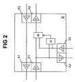
- Fig. 2 shows schematically the structure of a node device K.
- Each of the output or input units A1, A2, A3; E1, E2, E3 of the node device K contains, among others - in 2, not shown - components, an amplifier V, which here for easier determination of the direction of the Incoming node device K or the node device K leaving data packets is shown.
- Analogous to the representation in Fig. 1 is also only the respective signal wire in Fig. 2 shown without their associated ground wire.
- the second input unit E2 of the node device K is direct connected to the first output unit A1.
- the input unit E1 of the node device K is directly connected to the Output unit A3 and with an input of a multiplexer M wired.
- Another input of the multiplexer M is with the input unit E3 wired.
- the output of the multiplexer M is directly with the second output unit A2 of the node device K connected.
- the two inputs of a detector D of the node device K are connected to the first input unit E1 or the third input unit E3 connected.
- the exit of the detector D is with a control input of the multiplexer M connected.
- the multiplexer M provides, depending on the output signal a detector D, either the one on the first Input device E1 or that on the third input device E3 received data packets to those with the output of the multiplexer M wired second output device A2 through.
- the detector D detects an arrival of data packets the first and / or third input unit E1, E3 and controls the multiplexer M, which connects the input unit E1, E3 executes on the output unit A2 which determines the arrival of data packets by the detector becomes.
- the detector D controls the multiplexer M for switching to the other input unit E3, E1 suspended until a termination from detector D. of data traffic at the originally connected input unit E1, E3 is recognized.
- - is a detection of incoming data packets on the first Input unit E1, but not on the third input unit E3 - the first input unit E1 through the multiplexer M switched through to the second output unit A2, controls the detector D, in the case of incoming data packets at the third input unit E3, the multiplexer M not immediately to a connection of this third input unit E3 the second output unit A2, but only when the detector D an end to the arrival of data packets the input unit E1 is detected.
- the for the detection of the incoming data packets by the Detector D and those for switching the multiplexer M required time period can be temporarily to a perfect or partial loss of data packets on the second Lead output unit A2.
- There is also a temporary one Data loss if both input units E1, E3 at the same time Data packets arrive because the multiplexer M only one of the two input units E1, E3 to the second Output unit A2 can switch through.
- the Ethernet protocol ensures that overall the full record at the as the recipient of this Data packets declared device arrives.
- the ethernet protocol namely provides that a sending entity simultaneously the data packets transmitted on the data bus with the sent sent compares and so can recognize whether a correct Transmission, a transmission error, or a collision during of the send access has occurred. In the event of a transmission error - in this case a partial or complete Loss of individual data packets - is due to the Ethernet protocol try again at a later time provided by the sending institution.
- the devices EG do not have transmission access to the data bus B off, it is, together with its connecting line AL galvanically isolated from the data bus B by the multiplexer M. This reduces the length of the data bus B at times in which the facility EG does not carry out broadcast access.
- the galvanic decoupling of the third input unit E3 from the first input unit E1 through the multiplexer M also ensures that a device is plugged in EG a data stream sent via data bus B, that of the first input unit E1 via the multiplexer M is passed to the second output unit A2, does not interrupt.
- the power supply of the detector D, the multiplexer M and the input and output units E1, E2, E3; A1, A2, A3 can take place via the data bus B or alternatively, as in the exemplary embodiment, via an external power supply (not shown) and via corresponding power supply lines (not shown).
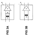
- FIG. 3A shows an input unit E of a node device K, consisting of a transformer Ü for galvanic decoupling the data signal from the data bus B, a resistor R, which serves as a line termination, and an amplifier V.
- Bei appropriate selection of the components of the input unit E, in particular the bandwidth of the amplifier V is a transmission method via the data bus B in the frequency range from 1-1000 MHz reachable.
- 3B shows an output unit A of a node device K, consisting of a transformer Ü and an amplifier V.
Applications Claiming Priority (2)
| Application Number | Priority Date | Filing Date | Title |
|---|---|---|---|
| DE10060938 | 2000-12-07 | ||
| DE10060938A DE10060938A1 (de) | 2000-12-07 | 2000-12-07 | Knoteneinrichtung für einen mehrere Einrichtungen verbindenden, seriellen Datenbus |
Publications (2)
| Publication Number | Publication Date |
|---|---|
| EP1213861A2 true EP1213861A2 (fr) | 2002-06-12 |
| EP1213861A3 EP1213861A3 (fr) | 2005-10-05 |
Family
ID=7666204
Family Applications (1)
| Application Number | Title | Priority Date | Filing Date |
|---|---|---|---|
| EP01125641A Withdrawn EP1213861A3 (fr) | 2000-12-07 | 2001-10-26 | Dispositif de noeud pour plusieurs dispositives étant réliés par un bus en série |
Country Status (3)
| Country | Link |
|---|---|
| US (1) | US6922742B2 (fr) |
| EP (1) | EP1213861A3 (fr) |
| DE (1) | DE10060938A1 (fr) |
Cited By (1)
| Publication number | Priority date | Publication date | Assignee | Title |
|---|---|---|---|---|
| US11411767B2 (en) | 2017-05-24 | 2022-08-09 | Wago Verwaltungsgesellschaft Mbh | Module unit for connecting a data bus subscriber |
Families Citing this family (3)
| Publication number | Priority date | Publication date | Assignee | Title |
|---|---|---|---|---|
| DE102011115431B4 (de) | 2011-10-08 | 2022-07-28 | Robert Bosch Gmbh | Feldbusnetzwerkadapter und Feldbusnetzwerkteilnehmer mit Feldbusanschlüssen |
| DE102017012228B4 (de) * | 2017-05-24 | 2020-06-18 | Wago Verwaltungsgesellschaft Mbh | Moduleinheit |
| DE102017012323B3 (de) * | 2017-05-24 | 2020-10-08 | Wago Verwaltungsgesellschaft Mbh | Moduleinheit |
Citations (3)
| Publication number | Priority date | Publication date | Assignee | Title |
|---|---|---|---|---|
| US5414708A (en) * | 1992-12-01 | 1995-05-09 | Farallon Computing, Inc. | Method and apparatus for connecting nodes for a computer network |
| US5513370A (en) * | 1992-12-22 | 1996-04-30 | National Semiconductor Corporation | Twisted pair and attachment unit interface (AUI) coding and transceiving circuit with full duplex, testing, isolation, and automatic output selection |
| EP1085705A2 (fr) * | 1999-09-16 | 2001-03-21 | Philips Corporate Intellectual Property GmbH | Réseau avec plusiers noeuds et au moins un noeud central |
Family Cites Families (7)
| Publication number | Priority date | Publication date | Assignee | Title |
|---|---|---|---|---|
| JPS59165537A (ja) * | 1983-03-10 | 1984-09-18 | Nec Corp | 光スタ−リピ−タ |
| US4837785A (en) * | 1983-06-14 | 1989-06-06 | Aptec Computer Systems, Inc. | Data transfer system and method of operation thereof |
| US5321394A (en) * | 1992-04-10 | 1994-06-14 | Alcatel Network Systems, Inc. | Spare card connection circuitry for high-speed telecommunications transmitters/receivers and methods |
| US5668814A (en) * | 1995-03-20 | 1997-09-16 | Raychem Corporation | Dual DDS data multiplexer |
| US5867484A (en) * | 1997-01-31 | 1999-02-02 | Intellect Network Technologies | Switchable multi-drop video distribution system |
| US6086430A (en) * | 1997-02-27 | 2000-07-11 | International Business Machines Corporation | Enhanced universal serial bus |
| US6157972A (en) * | 1997-12-05 | 2000-12-05 | Texas Instruments Incorporated | Apparatus and method for processing packetized information over a serial bus |
-
2000
- 2000-12-07 DE DE10060938A patent/DE10060938A1/de not_active Ceased
-
2001
- 2001-10-26 EP EP01125641A patent/EP1213861A3/fr not_active Withdrawn
- 2001-12-05 US US10/011,156 patent/US6922742B2/en not_active Expired - Fee Related
Patent Citations (3)
| Publication number | Priority date | Publication date | Assignee | Title |
|---|---|---|---|---|
| US5414708A (en) * | 1992-12-01 | 1995-05-09 | Farallon Computing, Inc. | Method and apparatus for connecting nodes for a computer network |
| US5513370A (en) * | 1992-12-22 | 1996-04-30 | National Semiconductor Corporation | Twisted pair and attachment unit interface (AUI) coding and transceiving circuit with full duplex, testing, isolation, and automatic output selection |
| EP1085705A2 (fr) * | 1999-09-16 | 2001-03-21 | Philips Corporate Intellectual Property GmbH | Réseau avec plusiers noeuds et au moins un noeud central |
Cited By (3)
| Publication number | Priority date | Publication date | Assignee | Title |
|---|---|---|---|---|
| US11411767B2 (en) | 2017-05-24 | 2022-08-09 | Wago Verwaltungsgesellschaft Mbh | Module unit for connecting a data bus subscriber |
| EP3632052B1 (fr) * | 2017-05-24 | 2023-03-08 | WAGO Verwaltungsgesellschaft mbH | Unité de module permettant de connecter un abonné de bus de données |
| US11936497B2 (en) | 2017-05-24 | 2024-03-19 | Wago Verwaltungsgesellschaft Mbh | Module unit for connecting a data bus subscriber |
Also Published As
| Publication number | Publication date |
|---|---|
| US20020097788A1 (en) | 2002-07-25 |
| DE10060938A1 (de) | 2002-06-27 |
| EP1213861A3 (fr) | 2005-10-05 |
| US6922742B2 (en) | 2005-07-26 |
Similar Documents
| Publication | Publication Date | Title |
|---|---|---|
| EP0458782B1 (fr) | Reseau en etoile de transmission de donnees entre des stations | |
| EP1342303B1 (fr) | Dispositif et procede permettant de transmettre des donnees de transmission numeriques | |
| DE69633504T2 (de) | Token-ring-netz-multiport-schalter | |
| EP2098019B1 (fr) | Système de communication présentant une structure maître-esclave | |
| EP0275464B1 (fr) | Dispositif émetteur-récepteur pour un système à bus | |
| EP0213063A1 (fr) | Circuit pour tester un système de bus passif (méthode d'accès CSMA/CD) | |
| EP2351291B1 (fr) | Appareil de transmission de données | |
| EP2594054B1 (fr) | Appareil de transport de transmission de données par câble entre deux véhicules reliés amovible l'un à l'autre | |
| DE2628753A1 (de) | Digitaldaten-uebertragungsnetz | |
| DE3225773A1 (de) | Elektrisch-optische schnittstellen-schaltungsanordnung | |
| DE3826895C2 (fr) | ||
| EP1886448B1 (fr) | Dispositif de mesure ou de protection universel | |
| EP0274679B1 (fr) | Dispositif émetteur-récepteur pour un système à bus | |
| DE19916894B4 (de) | Bussystem | |
| DE2211400C2 (de) | Zweistufiges Zeitmultiplex-Vermittlungssystem | |
| DE2828707A1 (de) | Ringfoermiges datenuebertragungssystem | |
| EP1213861A2 (fr) | Dispositif de noeud pour plusieurs dispositives étant réliés par un bus en série | |
| EP1062773B1 (fr) | Bus de donnees pour plusieurs noeuds | |
| EP0973295A2 (fr) | Réseau point à multipoint | |
| DE2459758A1 (de) | Verbindungseinheit zur exklusiven verbindung von zwei zweigleitungen in einer nachrichtenanlage | |
| EP0728581B1 (fr) | Système de bus pour une machine d'impression | |
| EP0348810B1 (fr) | Méthode pour l'adressage d'unités de processeur et circuit pour la mise en oeuvre de la méthode | |
| DE4225407C2 (de) | Kommunikationssystem | |
| DE102007029727B4 (de) | Netzwerk-Einspeisegerät zum Zwischenschalten zwischen einem Netzwerk-Verteiler und zumindest einem Netzwerk-Endgerät | |
| EP1162787B1 (fr) | Dispositif pour connecter des appareils à un réseau de données |
Legal Events
| Date | Code | Title | Description |
|---|---|---|---|
| PUAI | Public reference made under article 153(3) epc to a published international application that has entered the european phase |
Free format text: ORIGINAL CODE: 0009012 |
|
| AK | Designated contracting states |
Kind code of ref document: A2 Designated state(s): AT BE CH CY DE DK ES FI FR GB GR IE IT LI LU MC NL PT SE TR |
|
| AX | Request for extension of the european patent |
Free format text: AL;LT;LV;MK;RO;SI |
|
| PUAL | Search report despatched |
Free format text: ORIGINAL CODE: 0009013 |
|
| AK | Designated contracting states |
Kind code of ref document: A3 Designated state(s): AT BE CH CY DE DK ES FI FR GB GR IE IT LI LU MC NL PT SE TR |
|
| AX | Request for extension of the european patent |
Extension state: AL LT LV MK RO SI |
|
| AKX | Designation fees paid | ||
| STAA | Information on the status of an ep patent application or granted ep patent |
Free format text: STATUS: THE APPLICATION IS DEEMED TO BE WITHDRAWN |
|
| 18D | Application deemed to be withdrawn |
Effective date: 20060406 |
|
| REG | Reference to a national code |
Ref country code: DE Ref legal event code: 8566 |