EP1213861A2 - Node device for plural devices being connected by a serial data bus - Google Patents
Node device for plural devices being connected by a serial data bus Download PDFInfo
- Publication number
- EP1213861A2 EP1213861A2 EP01125641A EP01125641A EP1213861A2 EP 1213861 A2 EP1213861 A2 EP 1213861A2 EP 01125641 A EP01125641 A EP 01125641A EP 01125641 A EP01125641 A EP 01125641A EP 1213861 A2 EP1213861 A2 EP 1213861A2
- Authority
- EP
- European Patent Office
- Prior art keywords
- node device
- input unit
- data bus
- node
- output
- Prior art date
- Legal status (The legal status is an assumption and is not a legal conclusion. Google has not performed a legal analysis and makes no representation as to the accuracy of the status listed.)
- Withdrawn
Links
Images

Classifications
-
- H—ELECTRICITY
- H04—ELECTRIC COMMUNICATION TECHNIQUE
- H04L—TRANSMISSION OF DIGITAL INFORMATION, e.g. TELEGRAPHIC COMMUNICATION
- H04L12/00—Data switching networks
- H04L12/28—Data switching networks characterised by path configuration, e.g. LAN [Local Area Networks] or WAN [Wide Area Networks]
- H04L12/42—Loop networks
-
- H—ELECTRICITY
- H04—ELECTRIC COMMUNICATION TECHNIQUE
- H04L—TRANSMISSION OF DIGITAL INFORMATION, e.g. TELEGRAPHIC COMMUNICATION
- H04L12/00—Data switching networks
- H04L12/28—Data switching networks characterised by path configuration, e.g. LAN [Local Area Networks] or WAN [Wide Area Networks]
- H04L12/40—Bus networks
- H04L12/407—Bus networks with decentralised control
-
- H—ELECTRICITY
- H04—ELECTRIC COMMUNICATION TECHNIQUE
- H04L—TRANSMISSION OF DIGITAL INFORMATION, e.g. TELEGRAPHIC COMMUNICATION
- H04L49/00—Packet switching elements
- H04L49/30—Peripheral units, e.g. input or output ports
Definitions
- Ethernet is based on a serial Data bus with a plurality of connected to the data bus Facilities (e.g. data processing facilities or communication terminals), each at the same time can either receive or send data using a device before a broadcast access, i.e. sending a so-called Data packets, checks whether data packets are currently on the Data bus are sent and, if this is the case, broadcast access suspended by the facility becomes. Due to runtime effects that occur with longer data buses the case may arise that two institutions simultaneously send data packets over the data bus, making it to a collision between the different transmitters assigned data packets comes. This collision is in generally recognized by both sending entities that then interrupt the transmission access and only after one period chosen by the institutions again start.
- the data bus Facilities e.g. data processing facilities or communication terminals
- node facilities - becomes a local one Network, or in a configuration of the local network as Ethernet, the data bus, structured into individual segments.
- a node device is a station - often referred to in the literature as repeaters - trained, the data packets from a first segment of the data bus receives and this on a second segment of the data bus forwards.
- the forwarding is generally with signal regeneration, i.e. Reinforcement and reshaping the signal of the received data packets.
- signal regeneration i.e. Reinforcement and reshaping the signal of the received data packets.
- hubs Different designed node devices - in the literature often referred to as hubs - on the other hand, enable a star-shaped Connection of multiple facilities or segments to a data bus. Data packets can be compared to a repeater - generally after a comparable one Signal generation - identical on all connections of the hub passed on and the connections electrically isolated from each other and completed.
- the data transfer rate increases - And thus higher frequency of the data signals - to provide regular active node facilities, which deteriorate the signal quality due to signal regeneration and a termination of the signal-carrying lines compensate.
- An arrangement by which the signal quality in a local network can be preserved for example a variety of hubs, each via a short data bus are interconnected. Every hub concentrates several connected devices on one node of the data bus.
- This network design that is common for cabling is selected at building level, has the advantage of small segmentations on the one hand local network and thus a high quality of the signal quality, on the other hand, the resulting star-shaped turns out Topology disadvantageous for the effort of cabling the Network.
- the present invention has for its object a Specify node device through which a connection of devices to a data bus with little wiring effort can be achieved.
- a second pair of output / input units the node device with a first Output / input unit pair of a further node device connected in series and thus forms a serial data bus.
- a node device becomes a device, e.g. a data processing device or a communication terminal.
- This facility does not perform broadcast access the data bus is an output of the device through a multiplexers arranged in the node device from the data bus Cut.
- the facility has broadcast access started, the transmission of the device data packets sent by one in the node device Arranged detector detected that switching the Multiplexers on the assigned to the output of the device Arranged entrance of the node device. The data packet will thus directed to the second output of the node device.
- connection of the device to the data bus is only in switched through by the node device in those the device has transmit access to the data bus performs. So the total length of the data bus becomes like this kept as short as possible. The shorter bus length during breaks The facility has the advantage of better signal quality the data packets on the data bus are guaranteed can, because with increasing length of a data bus also the Signal impairments due to reflections and attenuation increase.
- An advantageous development of the invention provides that several node devices in a chain structure on the data bus can be arranged to provide additional facilities to connect one node device each to the data bus.
- Another embodiment of the invention provides feedback the second output unit to the node device which is the last link in the chain structure. By this further training becomes a ring topology of the data bus achieved an advantageous distribution of the data packets on the data bus.
- the Supply of the node devices with electrical energy via the data bus results in a saving on additional power supply lines for the node devices.
- those at node devices can also connected facilities with electrical energy can be supplied via the data bus.
- Fig. 1 shows a data bus B, which a plurality of node devices K1, K2, K3 connects in a chain.
- the node devices K1, K2, K3 each have three input units E1, E2, E3 and three output units A1, A2, A3. It is a first pair of output / input units A1, E1 of a node device K2 with a second pair of input / output units E2, A2 of the previous one in the chain structure Node device K1 and the second pair of output / input units A2, E2 of the node device K2 with a first input / output unit pair E1, A1 one in the Chain structure connected subsequent node device K3.
- Fig. 1 is indicated by wavy lines that after the Node device K3 as the illustrated end point of the chain structure further node devices can be arranged.
- node devices K1, K2, K3 can each above it third input / output unit pair E3, A3 - as in FIG. 1 shown for the node device K1 - one device EG (e.g. data processing equipment or communication terminals) are connected, the output unit A the device with the input unit E3 of the node device and the input unit E of the device with the output unit A3 of the node device is connected.
- the chain structure of the data bus B forming node devices K1, K2, K3 also - as in FIG. 1 shown for the node device K3 - another node device K4 can be connected, for example To reach branching of the data bus B.
- the node devices K1, ..., K4 are each as an Ethernet connection box executed to the via a standardized connector a connecting line AL a connection of the third Output or input unit A3, E3 to the input or Output unit E, A of the device EG are manufactured can.
- the architecture of the data bus B is based on this Embodiment to the specifications of the Ethernet.
- a four-core, twisted line is used as the transmission medium used with a symmetrical transmission method i.e. of these four wires of the line are two wires - one Signal wire and an associated ground wire - for the direction of transmission and accordingly reserved two wires for the direction of reception. 1 is in favor of a clearer Representation of the data bus B and the connecting cable AL, only the respective signal wire by hiding its associated Ground wire shown.
- the input units E1, E2, E3 and the output units A1, A2, A3 of the node devices K1, ..., K4 each point signal regenerating devices, e.g. Amplifier, on.
- Across from using the cabling already mentioned above one also with signal-regenerating functions equipped hubs is the wiring between chain-shaped arranged node devices to make easier than with a star-shaped topology, which is distinguished by its use of a stroke results.
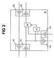
- Fig. 2 shows schematically the structure of a node device K.
- Each of the output or input units A1, A2, A3; E1, E2, E3 of the node device K contains, among others - in 2, not shown - components, an amplifier V, which here for easier determination of the direction of the Incoming node device K or the node device K leaving data packets is shown.
- Analogous to the representation in Fig. 1 is also only the respective signal wire in Fig. 2 shown without their associated ground wire.
- the second input unit E2 of the node device K is direct connected to the first output unit A1.
- the input unit E1 of the node device K is directly connected to the Output unit A3 and with an input of a multiplexer M wired.
- Another input of the multiplexer M is with the input unit E3 wired.
- the output of the multiplexer M is directly with the second output unit A2 of the node device K connected.
- the two inputs of a detector D of the node device K are connected to the first input unit E1 or the third input unit E3 connected.
- the exit of the detector D is with a control input of the multiplexer M connected.
- the multiplexer M provides, depending on the output signal a detector D, either the one on the first Input device E1 or that on the third input device E3 received data packets to those with the output of the multiplexer M wired second output device A2 through.
- the detector D detects an arrival of data packets the first and / or third input unit E1, E3 and controls the multiplexer M, which connects the input unit E1, E3 executes on the output unit A2 which determines the arrival of data packets by the detector becomes.
- the detector D controls the multiplexer M for switching to the other input unit E3, E1 suspended until a termination from detector D. of data traffic at the originally connected input unit E1, E3 is recognized.
- - is a detection of incoming data packets on the first Input unit E1, but not on the third input unit E3 - the first input unit E1 through the multiplexer M switched through to the second output unit A2, controls the detector D, in the case of incoming data packets at the third input unit E3, the multiplexer M not immediately to a connection of this third input unit E3 the second output unit A2, but only when the detector D an end to the arrival of data packets the input unit E1 is detected.
- the for the detection of the incoming data packets by the Detector D and those for switching the multiplexer M required time period can be temporarily to a perfect or partial loss of data packets on the second Lead output unit A2.
- There is also a temporary one Data loss if both input units E1, E3 at the same time Data packets arrive because the multiplexer M only one of the two input units E1, E3 to the second Output unit A2 can switch through.
- the Ethernet protocol ensures that overall the full record at the as the recipient of this Data packets declared device arrives.
- the ethernet protocol namely provides that a sending entity simultaneously the data packets transmitted on the data bus with the sent sent compares and so can recognize whether a correct Transmission, a transmission error, or a collision during of the send access has occurred. In the event of a transmission error - in this case a partial or complete Loss of individual data packets - is due to the Ethernet protocol try again at a later time provided by the sending institution.
- the devices EG do not have transmission access to the data bus B off, it is, together with its connecting line AL galvanically isolated from the data bus B by the multiplexer M. This reduces the length of the data bus B at times in which the facility EG does not carry out broadcast access.
- the galvanic decoupling of the third input unit E3 from the first input unit E1 through the multiplexer M also ensures that a device is plugged in EG a data stream sent via data bus B, that of the first input unit E1 via the multiplexer M is passed to the second output unit A2, does not interrupt.
- the power supply of the detector D, the multiplexer M and the input and output units E1, E2, E3; A1, A2, A3 can take place via the data bus B or alternatively, as in the exemplary embodiment, via an external power supply (not shown) and via corresponding power supply lines (not shown).
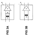
- FIG. 3A shows an input unit E of a node device K, consisting of a transformer Ü for galvanic decoupling the data signal from the data bus B, a resistor R, which serves as a line termination, and an amplifier V.
- Bei appropriate selection of the components of the input unit E, in particular the bandwidth of the amplifier V is a transmission method via the data bus B in the frequency range from 1-1000 MHz reachable.
- 3B shows an output unit A of a node device K, consisting of a transformer Ü and an amplifier V.
Landscapes
- Engineering & Computer Science (AREA)
- Computer Networks & Wireless Communication (AREA)
- Signal Processing (AREA)
- Small-Scale Networks (AREA)
- Information Transfer Systems (AREA)
Abstract
Description
Angesichts einer wachsenden Anzahl von an lokalen Netzwerken angeschlossenen Einrichtungen und einer gleichzeitigen steigenden Datenübertragungsrate in derartigen lokalen Netzwerken wird einerseits ein erhöhtes Augenmerk auf eine kostenoptimale Leitungsführung und andererseits auf Einrichtungen zur Gewährleistung einer möglichst hohen Signalqualität gelegt.Given a growing number of local networks connected facilities and a simultaneous rising Data transfer rate in such local networks on the one hand, increased attention is paid to cost-optimal Management and on the other hand on guarantee facilities the highest possible signal quality.
Eine der verwendeten Ausgestaltungsformen lokaler Netze ist das sogenannte Ethernet. Das Ethernet basiert auf einem seriellen Datenbus mit einer Mehrzahl von an den Datenbus angeschlossenen Einrichtungen (z.B. Datenverarbeitungseinrichtungen oder Kommunikationsendgeräte), die gleichzeitig jeweils entweder Daten empfangen oder senden können, wobei eine Einrichtung vor einem Sendezugriff, d.h. dem Senden eines sogenannten Datenpakets, prüft, ob gerade Datenpakete über den Datenbus gesendet werden und, in Fällen, in denen dies zutrifft, der Sendezugriff durch die Einrichtung ausgesetzt wird. Durch bei längeren Datenbussen auftretenden Laufzeiteffekten kann der Fall eintreten, dass zwei Einrichtungen gleichzeitig Datenpakete über den Datenbus senden, wodurch es zu einer Kollision der den unterschiedlichen Sendeeinrichtungen zugeordneten Datenpakete kommt. Diese Kollision wird in der Regel von beiden sendenden Einrichtungen erkannt, die daraufhin den Sendezugriff unterbrechen und erst nach einem von den Einrichtungen zufällig ausgewählten Zeitraum erneut starten.One of the forms of configuration used for local networks is the so-called ethernet. The Ethernet is based on a serial Data bus with a plurality of connected to the data bus Facilities (e.g. data processing facilities or communication terminals), each at the same time can either receive or send data using a device before a broadcast access, i.e. sending a so-called Data packets, checks whether data packets are currently on the Data bus are sent and, if this is the case, broadcast access suspended by the facility becomes. Due to runtime effects that occur with longer data buses the case may arise that two institutions simultaneously send data packets over the data bus, making it to a collision between the different transmitters assigned data packets comes. This collision is in generally recognized by both sending entities that then interrupt the transmission access and only after one period chosen by the institutions again start.
Durch verschiedene Arten von Kopplungselementen - im folgenden als Knoteneinrichtungen bezeichnet - wird ein lokales Netz, bzw. bei einer Ausgestaltung des lokalen Netzes als Ethernet, der Datenbus, in einzelne Segmente strukturiert. Through different types of coupling elements - in the following referred to as node facilities - becomes a local one Network, or in a configuration of the local network as Ethernet, the data bus, structured into individual segments.
Im einfachsten Fall ist eine Knoteneinrichtung als eine Station - in der Literatur häufig als Repeater bezeichnet - ausgebildet, die Datenpakete von einem ersten Segment des Datenbusses empfängt und diese auf ein zweites Segment des Datenbusses weiterleitet. Die Weiterleitung ist im allgemeinen mit einer Signalregenerierung, d.h. Verstärkung und Neuformung des Signals der empfangenen Datenpakete, verbunden. Des weiteren erfolgt zwischen den Anschlusseinheiten der Knoteneinrichtung eine elektrische Isolierung und ein Abschluss der Leitung, durch die eine Unterdrückung von Echoeffekten bewirkt wird.In the simplest case, a node device is a station - often referred to in the literature as repeaters - trained, the data packets from a first segment of the data bus receives and this on a second segment of the data bus forwards. The forwarding is generally with signal regeneration, i.e. Reinforcement and reshaping the signal of the received data packets. Furthermore takes place between the connection units of the node device electrical insulation and completion of the Line through which suppression of echo effects is effected becomes.
Anders ausgestaltete Knoteneinrichtungen - in der Literatur häufig als Hubs bezeichnet - ermöglichen dagegen eine sternförmige Anbindung mehrerer Einrichtungen oder auch Segmente an einen Datenbus. Vergleichbar mit einem Repeater werden Datenpakete - im allgemeinen nach einer ebenfalls vergleichbaren Signalgenerierung - an alle Anschlüsse des Hubs identisch weitergegeben und die Anschlüsse voneinander elektrisch isoliert und abgeschlossen.Different designed node devices - in the literature often referred to as hubs - on the other hand, enable a star-shaped Connection of multiple facilities or segments to a data bus. Data packets can be compared to a repeater - generally after a comparable one Signal generation - identical on all connections of the hub passed on and the connections electrically isolated from each other and completed.
Bei der Planung eines lokalen Netzes sind mit steigender Datenübertragungsrate - und damit höherer Frequenz der Datensignale - regelmäßig aktive Knoteneinrichtungen vorzusehen, die eine Verschlechterung der Signalqualität durch eine Signalregenerierung und einen Abschluss der signalführenden Leitungen kompensieren.When planning a local network, the data transfer rate increases - And thus higher frequency of the data signals - to provide regular active node facilities, which deteriorate the signal quality due to signal regeneration and a termination of the signal-carrying lines compensate.
Eine Anordnung, durch die die Signalqualität in einem lokalen netz erhalten werden kann, zeichnet sich beispielsweise durch eine Vielzahl von Hubs aus, die jeweils über einen kurzen Datenbus miteinander verbunden sind. Jeder Hub konzentriert dabei mehrere daran angeschlossene Einrichtungen auf einen Knoten des Datenbusses. Diese Netzwerkauslegung, die häufig für eine Verkabelung auf Etagenebene von Gebäuden gewählt wird, birgt einerseits den Vorteil von kleinen Segmentierungen eines lokalen Netzes und damit eine hohe Güte der Signalqualität, andererseits erweist sich die resultierende, sternförmige Topologie nachteilig für den Aufwand an Verkabelung des Netzwerkes.An arrangement by which the signal quality in a local network can be preserved, for example a variety of hubs, each via a short data bus are interconnected. Every hub concentrates several connected devices on one node of the data bus. This network design that is common for cabling is selected at building level, has the advantage of small segmentations on the one hand local network and thus a high quality of the signal quality, on the other hand, the resulting star-shaped turns out Topology disadvantageous for the effort of cabling the Network.
Der vorliegenden Erfindung liegt die Aufgabe zugrunde, eine Knoteneinrichtung anzugeben, durch die ein Anschluss von Einrichtungen an einen Datenbus mit geringen Verkabelungsaufwand erreicht werden kann.The present invention has for its object a Specify node device through which a connection of devices to a data bus with little wiring effort can be achieved.
Diese Aufgabe wird erfindungsgemäß durch die kennzeichnenden Merkmale des Patentanspruchs 1 gelöst.This object is achieved by the characterizing Features of claim 1 solved.
Erfindungsgemäß wird ein zweites Ausgangs-/Eingangseinheitenpaar der Knoteneinrichtung mit einem ersten Ausgangs-/Eingangseinheitenpaar einer weiteren Knoteneinrichtung in Serie geschaltet und bildet somit einen seriellen Datenbus. An einem dritten Ausgangs-/Eingangseinheitenpaar der Knoteneinrichtung wird eine Einrichtung, z.B. eine Datenverarbeitungseinrichtung oder ein Kommunikationsendgerät, angeschlossen. Führt diese Einrichtung keinen Sendezugriff auf den Datenbus aus, wird ein Ausgang der Einrichtung durch einen in der Knoteneinrichtung angeordneten Multiplexer vom Datenbus getrennt. Wird dagegen von der Einrichtung ein Sendezugriff gestartet, wird die Übermittlung der von der Einrichtung gesendeten Datenpakete durch einen in der Knoteneinrichtung angeordneten Detektor erkannt, der eine Umschaltung des Multiplexers auf den dem Ausgang der Einrichtung zugeordneten Eingang der Knoteneinrichtung veranlasst. Das Datenpaket wird somit auf den zweiten Ausgang der Knoteneinrichtung geleitet.According to the invention, a second pair of output / input units the node device with a first Output / input unit pair of a further node device connected in series and thus forms a serial data bus. On a third pair of output / input units A node device becomes a device, e.g. a data processing device or a communication terminal. This facility does not perform broadcast access the data bus is an output of the device through a multiplexers arranged in the node device from the data bus Cut. On the other hand, the facility has broadcast access started, the transmission of the device data packets sent by one in the node device Arranged detector detected that switching the Multiplexers on the assigned to the output of the device Arranged entrance of the node device. The data packet will thus directed to the second output of the node device.
Die Verbindung der Einrichtung mit dem Datenbus wird nur in den Fällen von der Knoteneinrichtung durchgeschaltet, in denen die Einrichtung einen Sendezugriff auf den Datenbus durchführt. Somit wird die Gesamtlänge des Datenbusses so kurz wie möglich gehalten. Die kürzere Buslänge bei Sendepausen der Einrichtung hat den Vorteil, dass eine bessere Signalqualität der Datenpakete am Datenbus gewährleistet werden kann, da mit zunehmender Länge eines Datenbusses auch die Signalbeeinträchtigungen durch Reflexionen und Dämpfung steigen.The connection of the device to the data bus is only in switched through by the node device in those the device has transmit access to the data bus performs. So the total length of the data bus becomes like this kept as short as possible. The shorter bus length during breaks The facility has the advantage of better signal quality the data packets on the data bus are guaranteed can, because with increasing length of a data bus also the Signal impairments due to reflections and attenuation increase.
Vorteilhafte Weiterbildungen der Erfindung sind in den Unteransprüchen angegeben.Advantageous developments of the invention are in the subclaims specified.
Eine vorteilhafte Weiterbildung der Erfindung sieht vor, dass mehrere Knoteneinrichtungen in einer Kettenstruktur am Datenbus angeordnet werden, um somit weitere Einrichtungen über jeweils eine Knoteneinrichtung an den Datenbus anzubinden. Eine weitere Ausgestaltung der Erfindung sieht die Rückführung der zweiten Ausgangseinheit auf die Knoteneinrichtung vor, die das letzte Glied der Kettenstruktur bildet. Durch diese Weiterbildung wird eine Ringtopologie des Datenbusses erreicht, die eine vorteilhafte Verteilung der Datenpakete auf dem Datenbus bewirkt.An advantageous development of the invention provides that several node devices in a chain structure on the data bus can be arranged to provide additional facilities to connect one node device each to the data bus. Another embodiment of the invention provides feedback the second output unit to the node device which is the last link in the chain structure. By this further training becomes a ring topology of the data bus achieved an advantageous distribution of the data packets on the data bus.
Durch eine Ausgestaltung der Eingangs- und Ausgangseinheiten mit signalregenerierenden Verstärkern und der Eingangseinheiten mit Leitungsabschlüssen wird eine hohe Signalqualität für die über den Datenbus übertragenen Datenpakete erreicht.By designing the input and output units with signal-regenerating amplifiers and the input units with line terminations is a high signal quality for reached the data packets transmitted via the data bus.
Gemäß einer weiteren Ausgestaltung der Erfindung erfolgt die Versorgung der Knoteneinrichtungen mit elektrischer Energie über den Datenbus. Auf diese Weise ergibt sich eine Einsparung an zusätzlichen Stromversorgungsleitungen für die Knoteneinrichtungen. Überdies können ebenfalls die an Knoteneinrichtungen angeschlossene Einrichtungen mit elektrischer Energie über den Datenbus versorgt werden.According to a further embodiment of the invention, the Supply of the node devices with electrical energy via the data bus. This results in a saving on additional power supply lines for the node devices. In addition, those at node devices can also connected facilities with electrical energy can be supplied via the data bus.
Ein Ausführungsbeispiel der Erfindung wird im Folgenden anhand der Zeichnung näher erläutert. An exemplary embodiment of the invention is described below the drawing explained in more detail.
Dabei zeigen
- Fig. 1:
- ein Strukturbild zur schematischen Darstellung der wesentlichen Funktionseinheiten eines Datenbusses;
- Fig. 2:
- ein Strukturbild zur schematischen Darstellung einer Knoteneinrichtung des Datenbusses;
- Fig. 3A:
- ein Strukturbild zur schematischen Darstellung einer Eingangseinheit der Knoteneinrichtung; und
- Fig. 3B:
- ein Strukturbild zur schematischen Darstellung einer Ausgangseinheit der Knoteneinrichtung.
- Fig. 1:
- a structural diagram for the schematic representation of the essential functional units of a data bus;
- Fig. 2:
- a structure diagram for the schematic representation of a node device of the data bus;
- Fig. 3A:
- a structural diagram for the schematic representation of an input unit of the node device; and
- 3B:
- a structural diagram for the schematic representation of an output unit of the node device.
Fig. 1 zeigt einen Datenbus B, der eine Mehrzahl von Knoteneinrichtungen K1,K2,K3 kettenförmig verbindet. Die Knoteneinrichtungen K1,K2,K3 weisen jeweils drei Eingangseinheiten E1,E2,E3 sowie drei Ausgangseinheiten A1,A2,A3 auf. Dabei ist ein erstes Ausgangs-/Eingangseinheitenpaar A1,E1 einer Knoteneinrichtung K2 mit einem zweiten Eingans-/Ausgangseinheitenpaar E2,A2 der in der Kettenstruktur vorausgehenden Knoteneinrichtung K1 und das zweite Ausgangs-/Eingangseinheitenpaar A2,E2 der Knoteneinrichtung K2 mit einem ersten Eingans-/Ausgangseinheitenpaar E1,A1 einer in der Kettenstruktur nachfolgenden Knoteneinrichtung K3 verbunden. Bei der den Anfang der Kettenstruktur bildenden Knoteneinrichtung K1 ist die erste Eingangseinheit E1 der Knoteneinrichtung K1 mit der ersten Ausgangseinheit A1 der Knoteneinrichtung K1 verbunden so dass der Datenbus B in einer ringförmigen Struktur geschlossen ist. In ähnlicher Weise wird am anderen Ende der Kettenstruktur, bei der dritten bzw. vierten Knoteneinrichtung K3,K4, verfahren, indem die jeweils zweite Eingangseinheit E2 mit der jeweils zweiten Ausgangseinheit A2 der jeweiligen Knoteneinrichtung K3,K4 verbunden wird. In Fig. 1 ist durch gewellte Linien angedeutet, dass nach der Knoteneinrichtung K3 als dargestellten Endpunkt der Kettenstruktur weitere Knoteneinrichtungen angeordnet sein können.Fig. 1 shows a data bus B, which a plurality of node devices K1, K2, K3 connects in a chain. The node devices K1, K2, K3 each have three input units E1, E2, E3 and three output units A1, A2, A3. It is a first pair of output / input units A1, E1 of a node device K2 with a second pair of input / output units E2, A2 of the previous one in the chain structure Node device K1 and the second pair of output / input units A2, E2 of the node device K2 with a first input / output unit pair E1, A1 one in the Chain structure connected subsequent node device K3. At the node device forming the beginning of the chain structure K1 is the first input unit E1 of the node device K1 with the first output unit A1 of the node device K1 connected so that the data bus B in an annular Structure is closed. Similarly, on other end of the chain structure, at the third or fourth Node device K3, K4, move by the second Input unit E2 with the respective second output unit A2 the respective node device K3, K4 is connected. In Fig. 1 is indicated by wavy lines that after the Node device K3 as the illustrated end point of the chain structure further node devices can be arranged.
An die Knoteneinrichtungen K1,K2,K3 können jeweils über ihr drittes Eingangs-/Ausgangseinheitenpaar E3,A3 - wie in Fig. 1 für die Knoteneinrichtung K1 dargestellt - eine Einrichtung EG (z.B. Datenverarbeitungseinrichtungen oder Kommunikationsendgeräte) angeschlossen werden, wobei die Ausgangseinheit A der Einrichtung mit der Eingangseinheit E3 der Knoteneinrichtung und die Eingangseinheit E der Einrichtung mit der Ausgangseinheit A3 der Knoteneinrichtung verbunden wird. Alternativ kann an jeder der die Kettenstruktur des Datenbusses B bildenden Knoteneinrichtungen K1,K2,K3 auch - wie in Fig. 1 für die Knoteneinrichtung K3 dargestellt - eine weitere Knoteneinrichtung K4 angeschlossen werden, um beispielsweise Verzweigung des Datenbusses B zu erreichen.To the node devices K1, K2, K3 can each above it third input / output unit pair E3, A3 - as in FIG. 1 shown for the node device K1 - one device EG (e.g. data processing equipment or communication terminals) are connected, the output unit A the device with the input unit E3 of the node device and the input unit E of the device with the output unit A3 of the node device is connected. alternative can the chain structure of the data bus B forming node devices K1, K2, K3 also - as in FIG. 1 shown for the node device K3 - another node device K4 can be connected, for example To reach branching of the data bus B.
Die Knoteneinrichtungen K1,...,K4 sind jeweils als Ethernetanschlussdose ausgeführt, an die über eine genormte Steckverbindung eine Anschlussleitung AL eine Verbindung der dritten Ausgangs- bzw. Eingangseinheit A3,E3 zu der Eingangs- bzw. Ausgangseinheit E,A der Einrichtung EG hergestellt werden kann.The node devices K1, ..., K4 are each as an Ethernet connection box executed to the via a standardized connector a connecting line AL a connection of the third Output or input unit A3, E3 to the input or Output unit E, A of the device EG are manufactured can.
Die Architektur des Datenbusses B lehnt sich im vorliegenden Ausführungsbeispiel an die Spezifikationen des Ethernets an. Als Übertragungsmedium wird eine vieradrige, verdrillte Leitung mit einem symmetrischen Übertragungsverfahren verwendet, d.h. von diesen vier Adern der Leitung sind zwei Adern - eine Signalader und eine zugehörige Masseader - für die Senderichtung und entsprechend zwei Adern für die Empfangsrichtung reserviert. In Fig. 1 ist, zugunsten einer übersichtlicheren Darstellung des Datenbusses B und der Anschlussleitung AL, nur die jeweilige Signalader unter Ausblendung ihrer zugehörigen Masseader dargestellt.The architecture of the data bus B is based on this Embodiment to the specifications of the Ethernet. A four-core, twisted line is used as the transmission medium used with a symmetrical transmission method i.e. of these four wires of the line are two wires - one Signal wire and an associated ground wire - for the direction of transmission and accordingly reserved two wires for the direction of reception. 1 is in favor of a clearer Representation of the data bus B and the connecting cable AL, only the respective signal wire by hiding its associated Ground wire shown.
Die Einganseinheiten E1,E2,E3 sowie die Ausgangseinheiten A1,A2,A3 der Knoteneinrichtungen K1,...,K4 weisen jeweils signalregenerierende Einrichtungen, z.B. Verstärker, auf. Gegenüber der bereits oben erwähnten Verkabelung unter Verwendung eines ebenfalls mit signalregenerierenden Funktionen ausgestatteten Hubs ist die Verkabelung zwischen kettenförmig angeordneten Knoteneinrichtungen einfacher zu gestalten als mit einer sternförmigen Topologie, die sich durch die Verwendung eines Hubs ergibt.The input units E1, E2, E3 and the output units A1, A2, A3 of the node devices K1, ..., K4 each point signal regenerating devices, e.g. Amplifier, on. Across from using the cabling already mentioned above one also with signal-regenerating functions equipped hubs is the wiring between chain-shaped arranged node devices to make easier than with a star-shaped topology, which is distinguished by its use of a stroke results.
Im Folgenden wird weiter auf die Funktionseinheiten der Fig. 1 Bezug genommen.In the following, the functional units of FIG. 1 referred.
Fig. 2 zeigt schematisch den Aufbau einer Knoteneinrichtung K. Jeder der Ausgangs- bzw. Eingangseinheiten A1,A2,A3; E1,E2,E3 der Knoteneinrichtung K enthält, neben anderen - in Fig. 2 nicht dargestellten - Komponenten, einen Verstärker V, der hier zur leichteren Bestimmung der Richtung der an der Knoteneinrichtung K eintreffenden bzw. die Knoteneinrichtung K verlassenden Datenpakete dargestellt ist. Analog zur Darstellung in Fig. 1 ist auch in Fig. 2 nur die jeweilige Signalader ohne deren zugehörige Masseader dargestellt.Fig. 2 shows schematically the structure of a node device K. Each of the output or input units A1, A2, A3; E1, E2, E3 of the node device K contains, among others - in 2, not shown - components, an amplifier V, which here for easier determination of the direction of the Incoming node device K or the node device K leaving data packets is shown. Analogous to the representation in Fig. 1 is also only the respective signal wire in Fig. 2 shown without their associated ground wire.
Die zweite Eingangseinheit E2 der Knoteneinrichtung K ist direkt mit der ersten Ausgangseinheit A1 verbunden. Die Eingangseinheit E1 der Knoteneinrichtung K ist direkt mit der Ausgangseinheit A3 sowie mit einem Eingang eines Multiplexers M verdrahtet. Ein weiterer Eingang des Multiplexers M ist mit der Eingangseinheit E3 verdrahtet. Der Ausgang des Multiplexers M ist direkt mit der zweiten Ausgangseinheit A2 der Knoteneinrichtung K verbunden. Die zwei Eingänge eines Detektors D der Knoteneinrichtung K sind mit der ersten Eingangseinheit E1 bzw. der dritten Eingangseinheit E3 verbunden. Der Ausgang des Detektors D ist mit einem Steuerungseingang des Multiplexers M verbunden. Der Multiplexer M stellt, abhängig vom Ausgangssignal eines Detektors D, entweder die an der ersten Eingangseinrichtung E1 oder die an der dritten Einganseinrichtung E3 empfangenen Datenpakete an die mit dem Ausgang des Multiplexers M verdrahteten zweiten Ausgangseinrichtung A2 durch.The second input unit E2 of the node device K is direct connected to the first output unit A1. The input unit E1 of the node device K is directly connected to the Output unit A3 and with an input of a multiplexer M wired. Another input of the multiplexer M is with the input unit E3 wired. The output of the multiplexer M is directly with the second output unit A2 of the node device K connected. The two inputs of a detector D of the node device K are connected to the first input unit E1 or the third input unit E3 connected. The exit of the detector D is with a control input of the multiplexer M connected. The multiplexer M provides, depending on the output signal a detector D, either the one on the first Input device E1 or that on the third input device E3 received data packets to those with the output of the multiplexer M wired second output device A2 through.
Der Detektor D detektiert ein Eintreffen von Datenpaketen an der ersten und/oder dritten Eingangseinheit E1,E3 und steuert den Multiplexer M, der eine Durchschaltung derjenigen Eingangseinheit E1,E3 auf die Ausgangseinheit A2 ausführt, an dem vom Detektor ein Eintreffen von Datenpaketen bestimmt wird.The detector D detects an arrival of data packets the first and / or third input unit E1, E3 and controls the multiplexer M, which connects the input unit E1, E3 executes on the output unit A2 which determines the arrival of data packets by the detector becomes.
Falls weder an der ersten noch an der dritten Eingangseinheit E1,E3 ein Datenstrom anliegt, ist durch den Multiplexer M die erste Eingangseinheit E1 auf die zweite Ausgangseinheit A2 durchgeschaltet. Wird nun an der dritten Eingangseinheit E3 vom Detektor D ein Signal durch eintreffende Datenpaketen erkannt, steuert dieser den Multiplexer M an, der eine Durchschaltung der dritten Eingangseinheit E3 auf die zweite Ausgangseinheit A2 veranlasst. Wird der Sendezugriff durch die Einrichtung EG beendet, ist im Detektor D eine Totzeit von beispielsweise 2µs vorgesehen, bevor dieser den Multiplexer M auf eine Umschaltung auf die erste Eingangseinheit E1 veranlasst, da der Detektor einen Ruhezustand - d.h. die Einrichtung EG (nicht dargestellt) führt keinen Sendezugriff aus - nicht von einem Senden einer aus mehreren logischen Nullen bestehenden Datensequenz unterscheiden kann.If neither on the first nor on the third input unit E1, E3 a data stream is present through the multiplexer M first input unit E1 to the second output unit A2 connected through. Now at the third input unit E3 a signal is recognized by detector D by incoming data packets, this drives the multiplexer M, which is a through-connection the third input unit E3 to the second output unit A2 initiated. If the send access by the Device EG ended, there is a dead time of in detector D. for example, 2µs before the multiplexer M prompted to switch over to the first input unit E1, since the detector is in an idle state - i.e. the establishment EG (not shown) does not perform send access - not from sending one of several logical zeros existing data sequence can distinguish.
Trifft während einer Durchschaltung des Multiplexers M von einer der Eingangseinheiten E1,E3 auf die zweite Ausgangseinheit A2 ein Datenpaket an der jeweils anderen Eingangseinheit E3, E1 ein, wird durch den Detektor D eine Steuerung des Multiplexers M zur Umschaltung auf die jeweils andere Eingangseinheit E3,E1 ausgesetzt, bis vom Detektor D eine Beendigung des Datenverkehrs an der ursprünglich durchgeschalteten Eingangseinheit E1,E3 erkannt wird. Ist beispielsweise - infolge einer Detektion von eintreffenden Datenpaketen an der ersten Eingangseinheit E1, nicht jedoch an der dritten Eingangseinheit E3 - die erste Eingangseinheit E1 durch den Multiplexer M auf die zweite Ausgangseinheit A2 durchgeschaltet, steuert der Detektor D, im Falle eintreffender Datenpakete an der dritten Eingangseinheit E3, den Multiplexer M nicht sofort auf eine Durchschaltung dieser dritten Eingangseinheit E3 auf die zweite Ausgangseinheit A2 an, sondern erst wenn vom Detektor D eine Beendigung des Eintreffens von Datenpaketen an der Eingangseinheit E1 detektiert wird.Strikes during a switching of the multiplexer M from one of the input units E1, E3 to the second output unit A2 a data packet at the other input unit E3, E1 on, the detector D controls the multiplexer M for switching to the other input unit E3, E1 suspended until a termination from detector D. of data traffic at the originally connected input unit E1, E3 is recognized. For example - is a detection of incoming data packets on the first Input unit E1, but not on the third input unit E3 - the first input unit E1 through the multiplexer M switched through to the second output unit A2, controls the detector D, in the case of incoming data packets at the third input unit E3, the multiplexer M not immediately to a connection of this third input unit E3 the second output unit A2, but only when the detector D an end to the arrival of data packets the input unit E1 is detected.
Die für die Detektion der eintreffenden Datenpakete durch den Detektor D sowie die für die Umschaltung des Multiplexers M benötigten Zeitspanne kann vorübergehend zu einem vollkommenen oder teilweisen Verlust der Datenpakete an der zweiten Ausgangseinheit A2 führen. Ebenso erfolgt ein vorübergehender Datenverlust, wenn an beiden Eingangseinheiten E1,E3 gleichzeitig Datenpakete eintreffen, da der Multiplexer M nur jeweils eine der beiden Eingangseinheiten E1,E3 auf die zweite Ausgangseinheit A2 durchschalten kann. In beiden Fällen ist jedoch durch das Ethernetprotokoll gewährleistet, dass insgesamt der vollständige Datensatz an der als Empfänger dieser Datenpakete deklarierten Einrichtung eintrifft. Das Ethernetprotokoll sieht nämlich vor, dass eine sendende Einrichtung gleichzeitig die am Datenbus übertragenen Datenpakete mit den gesendeten vergleicht und so erkennen kann, ob eine korrekte Übertragung, ein Übertragungsfehler oder eine Kollision während des Sendezugriffs aufgetreten ist. Im Falle eines Übertragungsfehlers - in diesem Fall ein teilweiser oder vollkommener Verlust einzelner Datenpakete - ist durch das Ethernetprotokoll zu einem späteren Zeitpunkt ein erneuter Sendeversuch durch die sendende Einrichtung vorgesehen.The for the detection of the incoming data packets by the Detector D and those for switching the multiplexer M required time period can be temporarily to a perfect or partial loss of data packets on the second Lead output unit A2. There is also a temporary one Data loss if both input units E1, E3 at the same time Data packets arrive because the multiplexer M only one of the two input units E1, E3 to the second Output unit A2 can switch through. In both cases however, the Ethernet protocol ensures that overall the full record at the as the recipient of this Data packets declared device arrives. The ethernet protocol namely provides that a sending entity simultaneously the data packets transmitted on the data bus with the sent sent compares and so can recognize whether a correct Transmission, a transmission error, or a collision during of the send access has occurred. In the event of a transmission error - in this case a partial or complete Loss of individual data packets - is due to the Ethernet protocol try again at a later time provided by the sending institution.
Führt die Einrichtungen EG keinen Sendezugriff auf den Datenbus B aus, ist sie, zusammen mit ihrer Anschlussleitung AL durch den Multiplexer M vom Datenbus B galvanisch getrennt. Dadurch verringert sich die Länge des Datenbusses B in Zeiten, in denen die Einrichtung EG keinen Sendezugriff ausführt. Die galvanische Entkopplung der dritten Eingangseinheit E3 von der ersten Eingangseinheit E1 durch den Multiplexer M gewährleistet weiterhin, dass ein Zustecken einer Einrichtung EG einen über den Datenbus B gesendeten Datenstrom, der von der ersten Eingangseinheit E1 über den Multiplexer M zur zweiten Ausgangseinheit A2 geleitet wird, nicht unterbricht. If the devices EG do not have transmission access to the data bus B off, it is, together with its connecting line AL galvanically isolated from the data bus B by the multiplexer M. This reduces the length of the data bus B at times in which the facility EG does not carry out broadcast access. The galvanic decoupling of the third input unit E3 from the first input unit E1 through the multiplexer M also ensures that a device is plugged in EG a data stream sent via data bus B, that of the first input unit E1 via the multiplexer M is passed to the second output unit A2, does not interrupt.
Die Stromversorgung des Detektor D, der Multiplexer M sowie die Eingangs- und Ausgangseinheiten E1,E2,E3; A1,A2,A3 kann über den Datenbus B erfolgen oder alternativ, wie im Ausführungsbeispiel, über ein externes Netzteil (nicht dargestellt) und über entsprechende Stromversorgungsleitungen (nicht dargestellt).The power supply of the detector D, the multiplexer M and the input and output units E1, E2, E3; A1, A2, A3 can take place via the data bus B or alternatively, as in the exemplary embodiment, via an external power supply (not shown) and via corresponding power supply lines (not shown).
Fig. 3A zeigt eine Eingangseinheit E einer Knoteneinrichtung K, bestehend aus einem Übertrager Ü für eine galvanische Entkopplung des Datensignals vom Datenbus B, einem Widerstand R, der als Leitungsabschluss dient, und einem Verstärker V. Bei entsprechender Wahl der Komponenten der Eingangseinheit E, insbesondere der Bandbreite des Verstärkers V, ist ein Übertragungsverfahren über den Datenbus B im Frequenzbereich von 1-1000 MHz erreichbar.3A shows an input unit E of a node device K, consisting of a transformer Ü for galvanic decoupling the data signal from the data bus B, a resistor R, which serves as a line termination, and an amplifier V. Bei appropriate selection of the components of the input unit E, in particular the bandwidth of the amplifier V is a transmission method via the data bus B in the frequency range from 1-1000 MHz reachable.
Fig. 3B zeigt eine Ausgangseinheit A einer Knoteneinrichtung K, bestehend aus einem Übertrager Ü und einem Verstärker V.3B shows an output unit A of a node device K, consisting of a transformer Ü and an amplifier V.
Claims (10)
dadurch gekennzeichnet, dass mehrere Knoteneinrichtungen (K1,...,K3) in einer Kettenstruktur am Datenbus (B) angeordnet sind,Node device according to claim 1,
characterized in that several node devices (K1, ..., K3) are arranged in a chain structure on the data bus (B),
dadurch gekennzeichnet, dass bei einer das letzte Glied der Kettenstruktur bildenden Knoteneinrichtung (K3) die zweite Ausgangseinheit (A2) auf die Knoteneinrichtung (K3) zurückgeführt wird. Node device according to claim 2,
characterized in that in the case of a node device (K3) forming the last link of the chain structure, the second output unit (A2) is returned to the node device (K3).
dadurch gekennzeichnet, dass die Eingangseinheiten (E1,E2,E3) bzw. Ausgangseinheiten (A1,A2,A3) der Knoteneinrichtungen (K1,...,K4) signalregenerierende Verstärker (V) aufweisen.Node device according to one of the preceding claims,
characterized in that the input units (E1, E2, E3) or output units (A1, A2, A3) of the node devices (K1, ..., K4) have signal-regenerating amplifiers (V).
dadurch gekennzeichnet, dass die signalregenerierenden Verstärker (V) der Eingangseinheiten (E1,E2,E3) jeweils eine Eingangstufe mit Leitungsabschluss aufweisen.Node device according to claim 4,
characterized in that the signal-regenerating amplifiers (V) of the input units (E1, E2, E3) each have an input stage with line termination.
dadurch gekennzeichnet, dass die Versorgung von Einrichtungen (EG) und Knoteneinrichtungen (K) mit elektrischer Energie über den Datenbus (B) erfolgt.Node device according to one of the preceding claims,
characterized in that the supply of devices (EG) and node devices (K) with electrical energy via the data bus (B).
dadurch gekennzeichnet, dass der Datenbus (B) gemäß dem Ethernetstandard ausgestaltet ist.Node device according to one of the preceding claims,
characterized in that the data bus (B) is designed in accordance with the Ethernet standard.
dadurch gekennzeichnet, dass anstelle einer Einrichtung (EG) an der dritten Ausgangseinheit (A3) der Knoteneinrichtung (K3) eine erste Eingangseinheit (E1) einer dritten Knoteneinrichtung (K4), bzw. dass an der dritten Eingangseinheit (A3) der Knoteneinrichtung (K3) eine erste Ausgangseinheit (A1) der dritten Knoteneinrichtung (K4) angeschlossen ist.Node device according to one of the preceding claims,
characterized in that instead of a device (EG) on the third output unit (A3) of the node device (K3), a first input unit (E1) of a third node device (K4), or that on the third input unit (A3) of the node device (K3) a first output unit (A1) of the third node device (K4) is connected.
dadurch gekennzeichnet, dass die Einrichtung (EG) eine Datenverarbeitungseinrichtung ist. Node device according to one of claims 1 to 7,
characterized in that the device (EG) is a data processing device.
dadurch gekennzeichnet, dass die Knoteneinrichtung (K1) als Anschlussdose zum Anschluss einer Anschlussleitung (AL) an die dritte Ausgangsbzw. Eingangeinheit (A3;E3) ausgestaltet ist.Node device according to one of the preceding claims,
characterized in that the node device (K1) as a junction box for connecting a connecting line (AL) to the third output or. Input unit (A3; E3) is configured.
Applications Claiming Priority (2)
| Application Number | Priority Date | Filing Date | Title |
|---|---|---|---|
| DE10060938 | 2000-12-07 | ||
| DE10060938A DE10060938A1 (en) | 2000-12-07 | 2000-12-07 | Node device for a serial data bus connecting several devices |
Publications (2)
| Publication Number | Publication Date |
|---|---|
| EP1213861A2 true EP1213861A2 (en) | 2002-06-12 |
| EP1213861A3 EP1213861A3 (en) | 2005-10-05 |
Family
ID=7666204
Family Applications (1)
| Application Number | Title | Priority Date | Filing Date |
|---|---|---|---|
| EP01125641A Withdrawn EP1213861A3 (en) | 2000-12-07 | 2001-10-26 | Node device for plural devices being connected by a serial data bus |
Country Status (3)
| Country | Link |
|---|---|
| US (1) | US6922742B2 (en) |
| EP (1) | EP1213861A3 (en) |
| DE (1) | DE10060938A1 (en) |
Cited By (1)
| Publication number | Priority date | Publication date | Assignee | Title |
|---|---|---|---|---|
| US11411767B2 (en) | 2017-05-24 | 2022-08-09 | Wago Verwaltungsgesellschaft Mbh | Module unit for connecting a data bus subscriber |
Families Citing this family (3)
| Publication number | Priority date | Publication date | Assignee | Title |
|---|---|---|---|---|
| DE102011115431B4 (en) | 2011-10-08 | 2022-07-28 | Robert Bosch Gmbh | Fieldbus network adapters and fieldbus network participants with fieldbus connections |
| DE102017012228B4 (en) * | 2017-05-24 | 2020-06-18 | Wago Verwaltungsgesellschaft Mbh | Module unit |
| DE102017012323B3 (en) * | 2017-05-24 | 2020-10-08 | Wago Verwaltungsgesellschaft Mbh | Modular unit |
Citations (3)
| Publication number | Priority date | Publication date | Assignee | Title |
|---|---|---|---|---|
| US5414708A (en) * | 1992-12-01 | 1995-05-09 | Farallon Computing, Inc. | Method and apparatus for connecting nodes for a computer network |
| US5513370A (en) * | 1992-12-22 | 1996-04-30 | National Semiconductor Corporation | Twisted pair and attachment unit interface (AUI) coding and transceiving circuit with full duplex, testing, isolation, and automatic output selection |
| EP1085705A2 (en) * | 1999-09-16 | 2001-03-21 | Philips Corporate Intellectual Property GmbH | Network with several nodes and at least one network hub |
Family Cites Families (7)
| Publication number | Priority date | Publication date | Assignee | Title |
|---|---|---|---|---|
| JPS59165537A (en) * | 1983-03-10 | 1984-09-18 | Nec Corp | Light star repeater |
| US4837785A (en) * | 1983-06-14 | 1989-06-06 | Aptec Computer Systems, Inc. | Data transfer system and method of operation thereof |
| US5321394A (en) * | 1992-04-10 | 1994-06-14 | Alcatel Network Systems, Inc. | Spare card connection circuitry for high-speed telecommunications transmitters/receivers and methods |
| US5668814A (en) * | 1995-03-20 | 1997-09-16 | Raychem Corporation | Dual DDS data multiplexer |
| US5867484A (en) * | 1997-01-31 | 1999-02-02 | Intellect Network Technologies | Switchable multi-drop video distribution system |
| US6086430A (en) * | 1997-02-27 | 2000-07-11 | International Business Machines Corporation | Enhanced universal serial bus |
| US6157972A (en) * | 1997-12-05 | 2000-12-05 | Texas Instruments Incorporated | Apparatus and method for processing packetized information over a serial bus |
-
2000
- 2000-12-07 DE DE10060938A patent/DE10060938A1/en not_active Ceased
-
2001
- 2001-10-26 EP EP01125641A patent/EP1213861A3/en not_active Withdrawn
- 2001-12-05 US US10/011,156 patent/US6922742B2/en not_active Expired - Fee Related
Patent Citations (3)
| Publication number | Priority date | Publication date | Assignee | Title |
|---|---|---|---|---|
| US5414708A (en) * | 1992-12-01 | 1995-05-09 | Farallon Computing, Inc. | Method and apparatus for connecting nodes for a computer network |
| US5513370A (en) * | 1992-12-22 | 1996-04-30 | National Semiconductor Corporation | Twisted pair and attachment unit interface (AUI) coding and transceiving circuit with full duplex, testing, isolation, and automatic output selection |
| EP1085705A2 (en) * | 1999-09-16 | 2001-03-21 | Philips Corporate Intellectual Property GmbH | Network with several nodes and at least one network hub |
Cited By (3)
| Publication number | Priority date | Publication date | Assignee | Title |
|---|---|---|---|---|
| US11411767B2 (en) | 2017-05-24 | 2022-08-09 | Wago Verwaltungsgesellschaft Mbh | Module unit for connecting a data bus subscriber |
| EP3632052B1 (en) * | 2017-05-24 | 2023-03-08 | WAGO Verwaltungsgesellschaft mbH | Module unit for connecting a data bus participant |
| US11936497B2 (en) | 2017-05-24 | 2024-03-19 | Wago Verwaltungsgesellschaft Mbh | Module unit for connecting a data bus subscriber |
Also Published As
| Publication number | Publication date |
|---|---|
| US6922742B2 (en) | 2005-07-26 |
| US20020097788A1 (en) | 2002-07-25 |
| DE10060938A1 (en) | 2002-06-27 |
| EP1213861A3 (en) | 2005-10-05 |
Similar Documents
| Publication | Publication Date | Title |
|---|---|---|
| DE3882307T2 (en) | LOCAL TRANSMISSION SYSTEM AND MEDIA ADAPTER FOR USE IN IT. | |
| EP0458782B1 (en) | Star-shaped network for data communication between stations | |
| EP1342303B1 (en) | System and method for the data transmission of digital transmission data | |
| DE3788337T2 (en) | Method and device for connecting computer workstations. | |
| DE69633504T2 (en) | TOKEN RING NETWORK MULTI PORT SWITCH | |
| DE69515853T2 (en) | SUBSCRIBER RETURN SYSTEM FOR FULL-SERVICE CABLE TELEVISION NETWORKS | |
| EP2098019B1 (en) | Communication system having a master/slave structure | |
| EP0275464B1 (en) | Emitter-receiver device for a bus system | |
| EP0213063A1 (en) | Circuit arrangement for testing a passive bus network (CSMA/CD access method) | |
| EP2351291B1 (en) | Data transmission device | |
| EP2594054B1 (en) | Apparatus for wired transmission of data between two vehicles which are detachably connected to one another | |
| DE2628753A1 (en) | DIGITAL DATA TRANSMISSION NETWORK | |
| DE3225773A1 (en) | ELECTRICAL-OPTICAL INTERFACE CIRCUIT ARRANGEMENT | |
| DE3826895C2 (en) | ||
| EP0274679B1 (en) | Emitter-receiver device for a bus system | |
| DE19916894B4 (en) | bus system | |
| DE2211400C2 (en) | Two-stage time division switching system | |
| DE2828707A1 (en) | RING-SHAPED DATA TRANSFER SYSTEM | |
| EP1213861A2 (en) | Node device for plural devices being connected by a serial data bus | |
| EP1062773B1 (en) | Data bus for a plurality of nodes | |
| DE19831954A1 (en) | Point-to-multipoint network | |
| EP0728581B1 (en) | Bus system for a printing machine | |
| EP0348810B1 (en) | Method for addressing processor units and circuit arrangement for carrying out the method | |
| DE4225407C2 (en) | Communication system | |
| DE102007029727B4 (en) | Network feeder for interposing between a network distributor and at least one network terminal |
Legal Events
| Date | Code | Title | Description |
|---|---|---|---|
| PUAI | Public reference made under article 153(3) epc to a published international application that has entered the european phase |
Free format text: ORIGINAL CODE: 0009012 |
|
| AK | Designated contracting states |
Kind code of ref document: A2 Designated state(s): AT BE CH CY DE DK ES FI FR GB GR IE IT LI LU MC NL PT SE TR |
|
| AX | Request for extension of the european patent |
Free format text: AL;LT;LV;MK;RO;SI |
|
| PUAL | Search report despatched |
Free format text: ORIGINAL CODE: 0009013 |
|
| AK | Designated contracting states |
Kind code of ref document: A3 Designated state(s): AT BE CH CY DE DK ES FI FR GB GR IE IT LI LU MC NL PT SE TR |
|
| AX | Request for extension of the european patent |
Extension state: AL LT LV MK RO SI |
|
| AKX | Designation fees paid | ||
| STAA | Information on the status of an ep patent application or granted ep patent |
Free format text: STATUS: THE APPLICATION IS DEEMED TO BE WITHDRAWN |
|
| 18D | Application deemed to be withdrawn |
Effective date: 20060406 |
|
| REG | Reference to a national code |
Ref country code: DE Ref legal event code: 8566 |