EP1213819A2 - Linear motor - Google Patents
Linear motor Download PDFInfo
- Publication number
- EP1213819A2 EP1213819A2 EP01129249A EP01129249A EP1213819A2 EP 1213819 A2 EP1213819 A2 EP 1213819A2 EP 01129249 A EP01129249 A EP 01129249A EP 01129249 A EP01129249 A EP 01129249A EP 1213819 A2 EP1213819 A2 EP 1213819A2
- Authority
- EP
- European Patent Office
- Prior art keywords
- magnetic pole
- pole tooth
- moving member
- linear motor
- trains
- Prior art date
- Legal status (The legal status is an assumption and is not a legal conclusion. Google has not performed a legal analysis and makes no representation as to the accuracy of the status listed.)
- Withdrawn
Links
Images


Classifications
-
- H—ELECTRICITY
- H02—GENERATION; CONVERSION OR DISTRIBUTION OF ELECTRIC POWER
- H02K—DYNAMO-ELECTRIC MACHINES
- H02K41/00—Propulsion systems in which a rigid body is moved along a path due to dynamo-electric interaction between the body and a magnetic field travelling along the path
- H02K41/02—Linear motors; Sectional motors
- H02K41/03—Synchronous motors; Motors moving step by step; Reluctance motors
- H02K41/031—Synchronous motors; Motors moving step by step; Reluctance motors of the permanent magnet type
Definitions
- This invention relates to a linear motor, and more particularly to a linear motor in which a moving member is interposed or sandwiched through a gap between magnetic pole teeth of an armature opposite to each other.
- the conventional linear motor comprises a stator having a plurality of magnetic pole members and a moving member supported so as to be movable relatively to the stator through a gap.
- the conventional linear motors are of a type cutting and opening a rotary machine and developing the opened rotary machine on a straight line.
- the conventional linear motor is complicated in construction since a plurality of windings are wound on one stator unit. Further, adjacent stator magnetic pole members are wound with windings different from each other. Therefore, there is much waste in the space that the stator occupies.
- An object of the present invention is to provide a linear motor which comprises a plurality of magnetic pole teeth while compact in construction because of the low number of windings and is capable of canceling out magnetic attracting forces acting between an armature and a moving member, in order to overcome the above defects of the conventional linear motor.
- Another object of the present invention is to provide a linear motor in which an amount of change in inductance to an amount of relative displacement between the armature and the moving member is so reduced that thrust ripples are reduced.
- a linear motor which comprises an armature; a moving member movable relatively to the armature; first and second magnetic pole tooth trains each comprising magnetic pole teeth magnetically coupled to one of two magnetic poles of the moving element, the first and second magnetic pole tooth trains being separated from each other in a direction substantially perpendicular to a moving direction of the moving member; and third and fourth magnetic pole tooth trains each comprising magnetic pole teeth magnetically coupled to the other of the two magnetic poles of the moving element, the third and fourth magnetic pole tooth trains being separated from each other in a direction substantially perpendicular to a moving direction of the moving member; the magnetic pole teeth of the first magnetic pole tooth train and the magnetic pole teeth of the third magnetic pole tooth train being alternately arranged in the moving direction of the moving member, the magnetic pole teeth of the second magnetic pole tooth train and the magnetic pole teeth of the fourth magnetic pole tooth train being alternately arranged in the moving direction of the moving member, and the moving member being arranged between the first and second magnetic pole tooth trains and the third and fourth magnetic
- a linear motor which further comprises means for reducing an amount of change in inductance to an amount of relative displacement between the armature and the moving member so as to reduce detent forces.
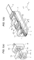
- Fig. 1A shows the basic configuration of an embodiment of a linear motor according to the present invention
- Fig. 1B shows a multi-magnetic pole tooth type of linear motor into which the basic configuration of the embodiment shown in Fig. 1A is expanded.
- numeral 51 designates a core having a first opposed portion, and numeral 52 a second opposed portion.
- the cores 51 and 52 are so constituted that upper and lower magnetic poles of one of the cores 51 and 52 are reverse in polarity to those of the other thereof.
- each of the cores 51 and 52 is wound with one winding as shown in Fig. 1A, a plurality of windings into which the one winding is divided may be wound on a plurality of portions of each of the cores 51 and 52.
- a mover or moving member 6 is interposed between the upper and lower magnetic pole teeth 11a and 21b of the core 51 and further between the upper and lower magnetic pole teeth 22a and 12b of the core 52, and is moved relatively to the armature.
- the armature comprises the core and a winding 4, and the moving member comprises a permanent magnet, magnetic member or non-magnetic member.
- a gap through which the moving member is interposed or sandwiched between the upper and lower magnetic pole teeth of each of the first and second opposed portions.
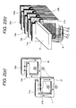
- Fig. 2A shows the basic configuration of another embodiment of a linear motor according to the present invention which is fabricated by using laminated steel plates, wherein the magnetic flux is generated in the direction indicated by arrows.
- Fig. 2B shows a multi-magnetic pole tooth type of linear motor into which the basic configuration of the embodiment shown in Fig. 2A is expanded and which is fabricated by using laminated steel plates.
- the magnetic flux is alternatingly generated in the vertical direction through the gap between the upper and lower magnetic pole teeth (11a, 22a and 21b, 12b) of the opposed portion of each armature 3.
- attracting forces acting between the moving member 6 and the upper magnetic pole teeth (11a, 22a) are approximately the same in magnitude as those acting between the moving member 6 and the lower magnetic pole teeth (21b, 12b) but reverse in direction thereto, so that the whole attracting forces become small. Therefore, since the attracting forces between the moving member 6 and the magnetic pole teeth of the armatures 3 can be reduced, the burdens on a moving member supporting mechanism can be reduced.
- the armature 3 is fabricated by using laminated steel plates and a plurality of first opposed portions and a plurality of second opposed portions are arranged. That core portion of the armature 3 which is wound with the winding 4 and the magnetic pole teeth between which the moving member 6 is interposed are separately fabricated by using laminated steel plates and combined with each other.
- Fig. 3 is a vertical side sectional view of the embodiment shown in Fig. 1A, 1B, 2A or 2B.
- moving member supporting mechanisms 14 and 15 are respectively attached to the armature 3 and the moving member 6 to support the moving member 6, so that the moving member 6 is moved relatively to the armature 3 through the gap 8 as if it passed a tunnel, with the moving member 6 supported by the moving member supporting mechanisms 14 and 15.
- Fig. 4 is a vertically exploded perspective illustration of the embodiment shown in Fig. 1B.
- Fig. 5 is a vertical front sectional illustration, of those portions of the upper and lower magnetic pole tooth trains which are opposed to the moving member, taken along the line C-C' of Fig. 4.
- an amount of change in inductance to an amount of relative displacement between both the upper magnetic pole tooth trains (11a, 22a, 13a, 24a, ⁇ ) and lower magnetic pole tooth trains (21b, 12b, 23b, 14b, ⁇ ) and magnetic poles with which the moving member 6 is increased, and therefore thrust ripples are also increased.
- the magnetic poles with which the moving member 6 is provided is of a permanent magnet type, they may be of a bumpy variable reluctance type, a combination type of the permanent magnet type and the bumpy variable reluctance type, or a winding type.
- Ps represents a pole pitch of the magnetic pole teeth.
- Fig. 6 is a vertically exploded perspective illustration of an additional embodiment of a linear motor according to the present invention.
- Fig. 7 is a vertical sectional illustration, of the opposite portions of the upper and lower magnetic pole tooth trains to the moving member, taken along the line C-C' of Fig. 6.
- each magnetic pole tooth to the moving member is provided with magnetic pole pieces 61 at both the ends thereof in the direction of movement of the moving member. Therefore, that portion of each magnetic pole tooth of the magnetic pole tooth trains which is opposed to the moving member is different in width from that portion of each magnetic pole tooth which is not opposed to the moving member.
- the depth dimension of each of the magnetic pole pieces may be the same as that of the opposite portion of each magnetic pole tooth to the moving member, or may be so adjusted as to become larger or smaller than the latter dimension as necessary.
- the pole piece 61 and each magnetic pole tooth may be integrally fabricated, or may be combined with each other after they are separately fabricated.
- Fig. 8 is a vertical sectional illustration of the opposite portions of the upper and lower magnetic pole tooth trains to the moving member of yet another embodiment of a linear motor according to the present invention.
- dummy magnetic poles 62 are provided between the adjacent different magnetic pole teeth.
- Fig. 9 is a vertical sectional illustration of the opposite portions of the upper and lower magnetic pole tooth trains to the moving member of a further embodiment of a linear motor according to the present invention.
- magnetic wedges 66 are provided between the adjacent different magnetic pole teeth.
- Fig. 10 is a vertical sectional illustration of the opposite portions of the upper and lower magnetic pole tooth trains to the moving member of a further additional embodiment of a linear motor according to the present invention.
- magnetic plates 63 are affixed or attached to opposite portions of the magnetic pole tooth trains to the moving member.
- the magnetic plates 63 each have guide plates 64 at both ends thereof in the direction of movement of the moving member 6 so that the same is easy to be introduced into the gap between the guide plates 64.
- the depth dimension of the dummy magnetic poles 62, the magnetic wedge 66 and the magnetic plates 63 may be the same as that of the opposite portion of each magnetic pole tooth to the moving member, or may be so adjusted as to become larger or smaller than the latter dimension as necessary.
- Fig. 11 is a vertical sectional illustration of the opposite portions of the upper and lower magnetic pole tooth trains to the moving member of still another embodiment of a linear motor according to the present invention.
- the opposite surface of each magnetic pole tooth to the moving member has grooves 65.
- the grooves 65 may be formed by laminating a plurality of steel plates which are different in size from one another, or cutting a solid magnetic material.
- Fig. 12 is a vertical sectional illustration of the opposite portions of upper and lower magnetic pole tooth trains to the moving member of also another embodiment of a linear motor according to the present invention.
- each pole tooth of the magnetic pole tooth trains comprises a plurality of magnetic pole tooth elements which are the same in magnetic polarity as one another and are arranged at predetermined intervals. Further, the embodiment shown in Fig. 12 is not provided with magnetic materials of the portions corresponding to the grooves of Fig. 11.
- Fig. 13 is a vertical sectional illustration of the opposite portions of upper and lower magnetic pole tooth trains to a moving member of a yet further embodiment of a linear motor according to the present invention.
- a gap or distance between the central portion of each magnetic pole tooth of the magnetic pole tooth trains and the moving member is different from that between the portion on each side of each magnetic pole tooth of the magnetic pole tooth trains and the moving member. That portion of each magnetic pole tooth which is not opposed to the moving member may not be the same in shape as the opposite portion of each magnetic pole tooth to the moving member.
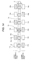
- Fig. 14 is a vertical sectional illustration of the opposite portions of upper and lower magnetic pole tooth trains to the moving member of a yet further additional embodiment of a linear motor according to the present invention.
- the moving member comprises permanent magnets and objects 70 which are arranged among the permanent magnets.
- the objects 70 are thicker than the permanent magnets in the direction of magnetization thereof. That is, thickness 71 of the permanent magnets is thinner than that of the objects 70.
- the permanent magnets are prevented from and protected against contacting the opposite portions of the upper magnetic pole teeth or the lower magnetic pole teeth to the moving member, even when the moving member is offset on the side of the upper or lower magnetic pole teeth.
- the armature is fixedly supported and the moving member is moved.
- the armature may be moved with the moving member supported fixedly.
- the present invention makes it possible to shorten the magnetic path of a magnetic circuit for the effective magnetic flux and to reduce magnetic leakage from the magnetic pole teeth, thereby allowing efficiency of the linear motor to be increased and power thereof to be raised.
- attracting forces acting between the moving member 6 and the upper magnetic pole teeth are approximately the same in magnitude as those acting between the moving member and the lower magnetic pole teeth but reverse in direction thereto, so that the whole attracting forces become small. Therefore, since the attracting forces between the moving member 6 and the magnetic pole teeth of the armatures 3 can be reduced, the burdens on the moving member supporting mechanism can be reduced.
Landscapes
- Engineering & Computer Science (AREA)
- Physics & Mathematics (AREA)
- Chemical & Material Sciences (AREA)
- Combustion & Propulsion (AREA)
- Electromagnetism (AREA)
- Power Engineering (AREA)
- Linear Motors (AREA)
Abstract
Description
Claims (12)
- A linear motor which comprises:an armature (3);a moving member (6) movable relatively to the armature;first (11a, 13a, 15a) and second (21b, 23b) magnetic pole tooth trains each comprising magnetic pole teeth magnetically coupled to one of two magnetic poles of the moving element, the first and second magnetic pole tooth trains being separated from each other in a direction substantially perpendicular to a moving direction of the moving member; andthird (22a, 24a) and fourth (12b) magnetic pole tooth trains each comprising magnetic pole teeth magnetically coupled to the other of the two magnetic poles of the moving element, the third and fourth magnetic pole tooth trains being separated from each other in a direction substantially perpendicular to a moving direction of the moving member;the magnetic pole teeth of the first magnetic pole tooth train and the magnetic pole teeth of the third magnetic pole tooth train being alternately arranged in the moving direction of the moving member, the magnetic pole teeth of the second magnetic pole tooth train and the magnetic pole teeth of the fourth magnetic pole tooth train being alternately arranged in the moving direction of the moving member, and the moving member being arranged between the first and second magnetic pole tooth trains and the third and fourth magnetic pole tooth trains.
- A linear motor according to claim 1, which further comprises means for reducing an amount of change in inductance to an amount of relative displacement between the armature and the moving member.
- A linear motor according to claim 1, which further comprises a magnetic plate attached to opposite portions of the magnetic pole tooth trains to the moving member.
- A linear motor according to claim 1, wherein that portion of each magnetic pole tooth of the magnetic pole tooth trains which is opposed to the moving member is different in width from that portion of each magnetic pole tooth which is not opposed to the moving member.
- A linear motor according to claim 1, which further comprises a dummy magnetic pole (62) provided between adjacent magnetic pole teeth different in magnetic polarity from each other in the magnetic pole tooth trains.
- A linear motor according to claim 1, which further comprises a magnetic wedge (66) provided between adjacent magnetic pole teeth different in magnetic polarity from each other in the magnetic pole tooth trains.
- A linear motor according to claim 1, wherein that surface of each magnetic pole tooth of the magnetic pole tooth trains which is opposed to the moving member has grooves (65).
- A linear motor according to claim 1, wherein each magnetic pole tooth of the magnetic pole tooth trains comprises a plurality of magnetic pole tooth elements which are the same in magnetic polarity as one another and are arranged at predetermined intervals.
- A linear motor according to claim 1, wherein a distance between a central portion of each magnetic pole tooth of the magnetic pole tooth trains and the moving member is different from that between a portion on each side of each magnetic pole tooth of the magnetic pole tooth trains and the moving member.
- A linear motor according to claim 1, wherein the moving member comprises permanent magnets and objects which are thicker than the permanent magnets in a direction of magnetization thereof, the objects being arranged among the permanent magnets.
- A linear motor according to claim 1 or 2, wherein the armature is fixedly supported and the moving member is moved.
- A linear motor according to claim 1 or 2, wherein the moving member is fixedly supported and the armature is moved.
Applications Claiming Priority (2)
| Application Number | Priority Date | Filing Date | Title |
|---|---|---|---|
| JP2000381640A JP3861593B2 (en) | 2000-12-11 | 2000-12-11 | Linear motor |
| JP2000381640 | 2000-12-11 |
Publications (2)
| Publication Number | Publication Date |
|---|---|
| EP1213819A2 true EP1213819A2 (en) | 2002-06-12 |
| EP1213819A3 EP1213819A3 (en) | 2003-01-22 |
Family
ID=18849603
Family Applications (1)
| Application Number | Title | Priority Date | Filing Date |
|---|---|---|---|
| EP01129249A Withdrawn EP1213819A3 (en) | 2000-12-11 | 2001-12-11 | Linear motor |
Country Status (4)
| Country | Link |
|---|---|
| US (1) | US6753627B2 (en) |
| EP (1) | EP1213819A3 (en) |
| JP (1) | JP3861593B2 (en) |
| CN (1) | CN1359187A (en) |
Cited By (3)
| Publication number | Priority date | Publication date | Assignee | Title |
|---|---|---|---|---|
| EP1378986A1 (en) * | 2002-07-02 | 2004-01-07 | Nti Ag | Constant force actuator |
| EP3047559A4 (en) * | 2013-09-18 | 2017-07-05 | Evr Motors Ltd. | Multipole electrical machine |
| WO2021092118A1 (en) * | 2019-11-07 | 2021-05-14 | Hyperloop Technologies, Inc. | Force-producing electromagnetic actuator |
Families Citing this family (16)
| Publication number | Priority date | Publication date | Assignee | Title |
|---|---|---|---|---|
| JP3395155B2 (en) * | 1999-05-07 | 2003-04-07 | 株式会社日立製作所 | Linear motor and manufacturing method thereof |
| SE524861C2 (en) * | 2002-08-14 | 2004-10-12 | Abb Ab | An electric machine and its use |
| JP3821101B2 (en) | 2003-02-04 | 2006-09-13 | 株式会社日立製作所 | Linear drive device, control method thereof, and XY table |
| JP4089597B2 (en) * | 2003-11-18 | 2008-05-28 | 株式会社日立製作所 | Linear motor and XY stage |
| JP4537745B2 (en) * | 2004-03-30 | 2010-09-08 | 株式会社日立製作所 | Linear motor |
| JPWO2007116508A1 (en) * | 2006-03-31 | 2009-08-20 | 株式会社日立製作所 | Linear motor |
| WO2007116505A1 (en) * | 2006-03-31 | 2007-10-18 | Hitachi, Ltd. | Linear motor |
| WO2007116506A1 (en) * | 2006-03-31 | 2007-10-18 | Hitachi, Ltd. | Linear motor |
| US8834088B2 (en) | 2007-11-12 | 2014-09-16 | Intevac, Inc. | Elevator linear motor drive |
| JP5434917B2 (en) | 2008-11-18 | 2014-03-05 | 日立金属株式会社 | Armature and linear motor |
| WO2010067837A1 (en) * | 2008-12-10 | 2010-06-17 | 株式会社日立製作所 | Thrust generation mechanism, drive device, xy stage, and xyz stage |
| TWI460966B (en) * | 2009-01-23 | 2014-11-11 | Hitachi Metals Ltd | Moving elements and linear motors |
| CN102934337B (en) * | 2010-06-09 | 2016-04-27 | 株式会社日立制作所 | The Blast Furnace Top Gas Recovery Turbine Unit (TRT) of generator and use generator |
| US8418350B2 (en) * | 2011-07-11 | 2013-04-16 | Baldor Electric Company | Method of forming a secondary for linear drive motor comprising sheet of highly permeable magnetic material having synchronized motor teeth, encoder teeth, and commutation tracks integrally formed therein |
| CN105222697A (en) * | 2015-10-23 | 2016-01-06 | 江门职业技术学院 | A kind of novel non-contact linear displacement transducer |
| EP3760565A1 (en) * | 2019-07-05 | 2021-01-06 | KONE Corporation | Electric linear motor |
Family Cites Families (19)
| Publication number | Priority date | Publication date | Assignee | Title |
|---|---|---|---|---|
| JPS5827752B2 (en) * | 1978-11-17 | 1983-06-11 | 松下電器産業株式会社 | straight electric machine |
| JPS5571169A (en) * | 1978-11-21 | 1980-05-29 | Matsushita Electric Ind Co Ltd | Straightly-moving electric machine |
| JPS5574356A (en) * | 1978-11-25 | 1980-06-04 | Matsushita Electric Ind Co Ltd | Linear electric machine |
| JPS5574359A (en) * | 1978-11-28 | 1980-06-04 | Matsushita Electric Ind Co Ltd | Linear electric machine |
| US4246505A (en) * | 1979-03-19 | 1981-01-20 | Hitachi, Ltd. | Rotor with salient poles and shield plates between the poles |
| WO1987002525A1 (en) * | 1985-10-12 | 1987-04-23 | Herbert Weh | Current converter-fed synchronous machine with permanent magnet excitation |
| US5331245A (en) * | 1986-01-13 | 1994-07-19 | Papst Licensing Gmbh | Permanent magnet excited electric motor with improved torque ripple |
| US4945268A (en) * | 1987-12-26 | 1990-07-31 | Hitachi, Ltd. | Permanent magnet type linear pulse motor |
| US4908533A (en) * | 1988-01-15 | 1990-03-13 | Shinko Electric Co., Ltd. | Transporting apparatus |
| AU3466893A (en) * | 1992-01-29 | 1993-09-01 | Stridsberg Innovation Ab | Brushless DC motors/generators |
| JPH1042531A (en) * | 1996-05-24 | 1998-02-13 | Matsushita Electric Ind Co Ltd | Electric motor |
| JP3488574B2 (en) * | 1996-07-19 | 2004-01-19 | ヤマハ発動機株式会社 | Linear motor |
| JP3791082B2 (en) | 1996-12-04 | 2006-06-28 | 株式会社安川電機 | Linear motor |
| JPH10290546A (en) * | 1997-02-13 | 1998-10-27 | Daido Steel Co Ltd | Cogging prevention structure for rotating electric machines |
| JP3818342B2 (en) * | 1997-10-06 | 2006-09-06 | 株式会社安川電機 | Linear motor |
| JPH11215748A (en) * | 1998-01-23 | 1999-08-06 | Toshiba Corp | Permanent magnet type rotating electric machine |
| JP3794160B2 (en) * | 1998-04-03 | 2006-07-05 | 松下電器産業株式会社 | Small linear pulse motor |
| JP2000175384A (en) * | 1998-12-09 | 2000-06-23 | Shin Etsu Chem Co Ltd | Permanent magnet motor |
| JP3395155B2 (en) * | 1999-05-07 | 2003-04-07 | 株式会社日立製作所 | Linear motor and manufacturing method thereof |
-
2000
- 2000-12-11 JP JP2000381640A patent/JP3861593B2/en not_active Expired - Fee Related
-
2001
- 2001-10-09 US US09/971,640 patent/US6753627B2/en not_active Expired - Fee Related
- 2001-12-11 EP EP01129249A patent/EP1213819A3/en not_active Withdrawn
- 2001-12-11 CN CN01143551.8A patent/CN1359187A/en active Pending
Cited By (10)
| Publication number | Priority date | Publication date | Assignee | Title |
|---|---|---|---|---|
| EP1378986A1 (en) * | 2002-07-02 | 2004-01-07 | Nti Ag | Constant force actuator |
| EP3047559A4 (en) * | 2013-09-18 | 2017-07-05 | Evr Motors Ltd. | Multipole electrical machine |
| US10056813B2 (en) | 2013-09-18 | 2018-08-21 | E.V.R. Motors Ltd. | Multipole electrical machine |
| WO2021092118A1 (en) * | 2019-11-07 | 2021-05-14 | Hyperloop Technologies, Inc. | Force-producing electromagnetic actuator |
| US11848595B2 (en) | 2019-11-07 | 2023-12-19 | Hyperloop Technologies, Inc. | Channel segment for a track of a mover device |
| US11936271B2 (en) | 2019-11-07 | 2024-03-19 | Hyperloop Technologies, Inc. | Replaceable windings for an electromagnetic machine |
| US11962212B2 (en) | 2019-11-07 | 2024-04-16 | Hyperloop Technologies, Inc. | Electrical windings for a low pressure environment |
| US12003158B2 (en) | 2019-11-07 | 2024-06-04 | Hyperloop Technologies, Inc. | Force-producing electromagnetic machine |
| US12355325B2 (en) | 2019-11-07 | 2025-07-08 | Hyperloop Technologies, Inc. | System, electromagnetic actuator and track for braking |
| US12512742B2 (en) | 2019-11-07 | 2025-12-30 | Dp World Logistics Us Holdings, Inc. | Force-producing electromagnetic actuator |
Also Published As
| Publication number | Publication date |
|---|---|
| JP3861593B2 (en) | 2006-12-20 |
| EP1213819A3 (en) | 2003-01-22 |
| CN1359187A (en) | 2002-07-17 |
| JP2002186243A (en) | 2002-06-28 |
| US6753627B2 (en) | 2004-06-22 |
| US20020070612A1 (en) | 2002-06-13 |
Similar Documents
| Publication | Publication Date | Title |
|---|---|---|
| US6753627B2 (en) | Linear motor | |
| JP2000037070A (en) | Linear motor | |
| EP1198055B1 (en) | Linear motor, driving and control system thereof and manufacturing method thereof | |
| KR100775423B1 (en) | Door system | |
| JP2001028875A (en) | Linear motor and manufacturing method thereof | |
| JP4788986B2 (en) | Linear motor | |
| JP4938355B2 (en) | Linear motor | |
| JP3220537B2 (en) | Linear pulse motor | |
| JP4061834B2 (en) | Linear motor | |
| JP2004364374A (en) | Linear motor | |
| JP2005117856A (en) | Moving magnet type linear actuator | |
| JP2002209371A (en) | Linear motor | |
| JP3817883B2 (en) | Linear motor | |
| JPH08205514A (en) | Linear synchronous motor | |
| JP2009219199A (en) | Linear motor | |
| JP2001211630A (en) | Linear slider | |
| JP4110335B2 (en) | Linear motor | |
| JP3944766B2 (en) | Permanent magnet synchronous linear motor | |
| JP2785406B2 (en) | Linear servo motor | |
| JP3175554B2 (en) | DC linear motor | |
| JP2006527576A (en) | Linear brushless DC motor with an iron core with reduced detent power | |
| JP2002119040A (en) | Linear motor | |
| JP4497986B2 (en) | Claw pole type three-phase linear motor | |
| JPH10174419A (en) | Pulse motor | |
| JP2001008432A (en) | Linear motor |
Legal Events
| Date | Code | Title | Description |
|---|---|---|---|
| PUAI | Public reference made under article 153(3) epc to a published international application that has entered the european phase |
Free format text: ORIGINAL CODE: 0009012 |
|
| AK | Designated contracting states |
Kind code of ref document: A2 Designated state(s): AT BE CH CY DE DK ES FI FR GB GR IE IT LI LU MC NL PT SE TR |
|
| AX | Request for extension of the european patent |
Free format text: AL;LT;LV;MK;RO;SI |
|
| PUAL | Search report despatched |
Free format text: ORIGINAL CODE: 0009013 |
|
| AK | Designated contracting states |
Kind code of ref document: A3 Designated state(s): AT BE CH CY DE DK ES FI FR GB GR IE IT LI LU MC NL PT SE TR |
|
| AX | Request for extension of the european patent |
Free format text: AL;LT;LV;MK;RO;SI |
|
| 17P | Request for examination filed |
Effective date: 20030522 |
|
| AKX | Designation fees paid |
Designated state(s): DE FR GB |
|
| 17Q | First examination report despatched |
Effective date: 20040324 |
|
| STAA | Information on the status of an ep patent application or granted ep patent |
Free format text: STATUS: THE APPLICATION IS DEEMED TO BE WITHDRAWN |
|
| 18D | Application deemed to be withdrawn |
Effective date: 20040805 |