EP1212532B1 - Dual diaphragm pump - Google Patents
Dual diaphragm pump Download PDFInfo
- Publication number
- EP1212532B1 EP1212532B1 EP00965096A EP00965096A EP1212532B1 EP 1212532 B1 EP1212532 B1 EP 1212532B1 EP 00965096 A EP00965096 A EP 00965096A EP 00965096 A EP00965096 A EP 00965096A EP 1212532 B1 EP1212532 B1 EP 1212532B1
- Authority
- EP
- European Patent Office
- Prior art keywords
- diaphragm
- pump
- diaphragms
- fluid
- pump chamber
- Prior art date
- Legal status (The legal status is an assumption and is not a legal conclusion. Google has not performed a legal analysis and makes no representation as to the accuracy of the status listed.)
- Expired - Lifetime
Links
- 230000009977 dual effect Effects 0.000 title description 3
- 239000012530 fluid Substances 0.000 claims abstract description 40
- 238000007789 sealing Methods 0.000 claims abstract description 14
- 238000004891 communication Methods 0.000 claims abstract description 8
- 238000005086 pumping Methods 0.000 claims description 14
- 238000000034 method Methods 0.000 claims description 8
- 239000010410 layer Substances 0.000 description 9
- XUIMIQQOPSSXEZ-UHFFFAOYSA-N Silicon Chemical compound [Si] XUIMIQQOPSSXEZ-UHFFFAOYSA-N 0.000 description 8
- 229910052710 silicon Inorganic materials 0.000 description 8
- 239000010703 silicon Substances 0.000 description 8
- 238000013461 design Methods 0.000 description 6
- 238000005516 engineering process Methods 0.000 description 5
- 238000003491 array Methods 0.000 description 4
- 239000012528 membrane Substances 0.000 description 4
- 230000002441 reversible effect Effects 0.000 description 4
- 238000005070 sampling Methods 0.000 description 3
- VYPSYNLAJGMNEJ-UHFFFAOYSA-N Silicium dioxide Chemical compound O=[Si]=O VYPSYNLAJGMNEJ-UHFFFAOYSA-N 0.000 description 2
- 230000000694 effects Effects 0.000 description 2
- 238000000465 moulding Methods 0.000 description 2
- 239000000126 substance Substances 0.000 description 2
- 241000271274 Cleopatra Species 0.000 description 1
- 230000004913 activation Effects 0.000 description 1
- 238000004458 analytical method Methods 0.000 description 1
- 238000013459 approach Methods 0.000 description 1
- -1 biological Substances 0.000 description 1
- 239000012620 biological material Substances 0.000 description 1
- 230000015556 catabolic process Effects 0.000 description 1
- 238000006243 chemical reaction Methods 0.000 description 1
- 239000003795 chemical substances by application Substances 0.000 description 1
- 229910052681 coesite Inorganic materials 0.000 description 1
- 238000010276 construction Methods 0.000 description 1
- 229910052906 cristobalite Inorganic materials 0.000 description 1
- 238000006731 degradation reaction Methods 0.000 description 1
- 238000001514 detection method Methods 0.000 description 1
- 238000011161 development Methods 0.000 description 1
- 238000010586 diagram Methods 0.000 description 1
- 238000006073 displacement reaction Methods 0.000 description 1
- 238000012377 drug delivery Methods 0.000 description 1
- 230000008030 elimination Effects 0.000 description 1
- 238000003379 elimination reaction Methods 0.000 description 1
- 239000002360 explosive Substances 0.000 description 1
- 230000000977 initiatory effect Effects 0.000 description 1
- 239000000463 material Substances 0.000 description 1
- 239000002184 metal Substances 0.000 description 1
- 238000004377 microelectronic Methods 0.000 description 1
- 239000002991 molded plastic Substances 0.000 description 1
- 239000002245 particle Substances 0.000 description 1
- 230000001105 regulatory effect Effects 0.000 description 1
- 230000029058 respiratory gaseous exchange Effects 0.000 description 1
- 239000004065 semiconductor Substances 0.000 description 1
- 239000000377 silicon dioxide Substances 0.000 description 1
- 239000002356 single layer Substances 0.000 description 1
- 239000007787 solid Substances 0.000 description 1
- 229910052682 stishovite Inorganic materials 0.000 description 1
- 238000012546 transfer Methods 0.000 description 1
- 229910052905 tridymite Inorganic materials 0.000 description 1
Images

Classifications
-
- F—MECHANICAL ENGINEERING; LIGHTING; HEATING; WEAPONS; BLASTING
- F04—POSITIVE - DISPLACEMENT MACHINES FOR LIQUIDS; PUMPS FOR LIQUIDS OR ELASTIC FLUIDS
- F04B—POSITIVE-DISPLACEMENT MACHINES FOR LIQUIDS; PUMPS
- F04B43/00—Machines, pumps, or pumping installations having flexible working members
- F04B43/02—Machines, pumps, or pumping installations having flexible working members having plate-like flexible members, e.g. diaphragms
- F04B43/04—Pumps having electric drive
- F04B43/043—Micropumps
-
- A—HUMAN NECESSITIES
- A61—MEDICAL OR VETERINARY SCIENCE; HYGIENE
- A61M—DEVICES FOR INTRODUCING MEDIA INTO, OR ONTO, THE BODY; DEVICES FOR TRANSDUCING BODY MEDIA OR FOR TAKING MEDIA FROM THE BODY; DEVICES FOR PRODUCING OR ENDING SLEEP OR STUPOR
- A61M5/00—Devices for bringing media into the body in a subcutaneous, intra-vascular or intramuscular way; Accessories therefor, e.g. filling or cleaning devices, arm-rests
- A61M5/14—Infusion devices, e.g. infusing by gravity; Blood infusion; Accessories therefor
- A61M5/142—Pressure infusion, e.g. using pumps
- A61M5/14212—Pumping with an aspiration and an expulsion action
- A61M5/14224—Diaphragm type
-
- A—HUMAN NECESSITIES
- A61—MEDICAL OR VETERINARY SCIENCE; HYGIENE
- A61M—DEVICES FOR INTRODUCING MEDIA INTO, OR ONTO, THE BODY; DEVICES FOR TRANSDUCING BODY MEDIA OR FOR TAKING MEDIA FROM THE BODY; DEVICES FOR PRODUCING OR ENDING SLEEP OR STUPOR
- A61M5/00—Devices for bringing media into the body in a subcutaneous, intra-vascular or intramuscular way; Accessories therefor, e.g. filling or cleaning devices, arm-rests
- A61M5/14—Infusion devices, e.g. infusing by gravity; Blood infusion; Accessories therefor
- A61M5/142—Pressure infusion, e.g. using pumps
- A61M5/14244—Pressure infusion, e.g. using pumps adapted to be carried by the patient, e.g. portable on the body
- A61M5/14276—Pressure infusion, e.g. using pumps adapted to be carried by the patient, e.g. portable on the body specially adapted for implantation
Definitions
- the present invention relates to a mesopump. More particularly the invention relates to a mesopump having reduced pump volume and weight for a given fluid pumping rate due to its compact design.
- the Government may have rights in this invention pursuant to Contract No. DABT63-97-C-0071, awarded by the Department of the Army.
- micropumps The pumping capability of these micropumps is in one to tens of microliters per minute range. This makes them useful for applications such as implantable systems for drug delivery or micro dosage in chemical analysis systems but such pumping speeds are many orders of magnitude smaller than those required in sampling applications.
- US-A-2195792 discloses a pump or compressor having a plurality of relatively spaced disklike members within a body, which actuate fluid within the body from an inlet towards an outlet of the body.
- mesopumps could be developed with inlet and outlet ports in the center of the chamber to eliminate lateral channels.
- a diaphragm pump comprising:
- the present invention also provides a method of pumping fluids using a diaphragm pump, comprising the steps of:
- the present invention provides an electrostatically actuated diaphragm pump.
- the pump consists of a single molded plastic chamber with two thin diaphragms staked directly on top of each other.
- the diaphragms may be actuated with electrostatic, electromagnetic, or piezoelectric methods.
- the electrostatic actuation approach may be implemented in a similar manner to previous designs such as those in the above-referenced patent applications and patents.
- the unique feature of the present invention is the use of a single chamber for pumping, as distinguished from the prior art where three chambers are required.
- Each diaphragm has its own set of valving holes, wherein the holes in the upper and lower diaphragm are offset so that the surfaces form a sealed surface when they are electrostatically pulled together, yet allow flow through the diaphragm when separated.
- At least one inlet port and at least one outlet port are provided in the pump body for communication with the pump chamber.
- the ports are positioned to be sealed by the diaphragm by insuring contact with the diaphragms at a point nonaligned with the holes in the diaphragm.
- the inlet port may be located on the top of the pump chamber for engagement with the first diaphragm to open and close the inlet port.
- the outlet port may be positioned on the bottom of the pump chamber for engagement with the second diaphragm to open and close the outlet port. Since the pump of this invention is reversible, of course, the bottom and top are mere nomenclature and reverse terminology could be used to refer to the inlet/outlet positions.
- the pumps of the present invention may be formed into an array formed from a plurality of electrostatically actuated diaphragm pumps according to the present invention. These plurality of pumps may be connected through the inlet and outlet ports in parallel to form a sheet-like array, and, even to form multiple layers of sheets of the pumps. Alternatively, the plurality of pumps may be connected through the inlet and outlet ports in series. Both forms are contemplated by the present invention.
- Fig. 1 shows the present invention, 10 generally, in cross section, with a body 11 defining a chamber having an upper region 13 a middle region 14 and a lower region 15.
- the chamber is separated into three regions by the upper and lower diaphragms 17 and 19, respectively, and the volume of each region is determined by the position of the diaphragms.
- Control electronics 21 provides voltage potentials V1, V2 and V3.
- each diaphragm has a separate electrode, as do the upper and lower surfaces of the chamber.
- the upper and lower surfaces of each diaphragm and the upper and lower surfaces of the bump chamber may be shorted to the same potential, so that only three control voltages are required. It is known to move diaphragms in chambers electrostatically by application of a voltage to one or more electrodes, and it is contemplated that the present invention will employ those techniques to accomplish the movements of diaphragm into and out of contact with each other and with the chamber itself.
- Each electrode consists of a conductive metal layer coated with a dielectric to prevent shorting between electrodes, as is known in the art.
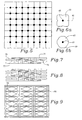
- Diaphragms 17 and 19 have a plurality of holes 27 and 29, respectively, which permit passage of fluid through the diaphragm Holes 27 and 29 are nonaligned or positioned so that no hole in diaphragm 17 overlays any hole in diaphragm 19.
- Fig. 2 illustrates this arrangement, with the upper holes 27 in solid on diaphragm 17, and lower holes 29 in dotted line to illustrate they are located on lower diaphragm 29.
- the two diaphragms 17 and 19 are electrostatically pulled together, they form a sealed surface, yet allow flow through the diaphragm if actuated individually.
- upper port 33 communicates with upper chamber 13 and lower port 35 communicates with lower chamber 15.
- the upper chamber region 13 communicates with the middle region 14 via the upper holes 27, and the lower chamber region 15 communicates with the middle region 14 via the lower holes 29. Since fluid flow can be either in or out of port 33 and 35, both ports 33 and 35 will serve as an inlet or an outlet, depending on the configuration of the pump and attendant equipment during use of the pump.
- Figs. 3a-3f illustrate a pumping sequence where the inlet is on the bottom. An opposite configuration is equally appropriate since the pump is completely reversible.
- Figs. 3a illustrates the orientation where both diaphragms 17 and 19 have been pulled down, thus sealing lower port 35. Fluid is assumed to be contained in upper chamber 13, while middle chamber 14 and the lower chamber 15 are essentially eliminated by the position of the two diaphragms 17 and 19. As noted above, holes 27 and 29 in diaphragms 17 and 19 do not align with each other or with either port 33 or 35, to effect the desired seal.
- Fig. 3b illustrates the initiation of the pump stroke by simultaneously moving diaphragms 17 and 19 together upward toward the top.
- FIG. 3c shows completion of the pump stroke, with both diaphragms 17 and 19 pushed up, thus sealing upper port 33. All of the fluid in chamber 13 of Fig. 3a has been expelled in Fig. 3c through upper port 33 and lower port 35 is open, so that the fluid is drawn into the lower chamber 15 through lower port 35.
- the upper diaphragm 17 remains in sealing relationship with upper port 33 while lower diaphragm 19 is pulled down, causing the fluid in lower chamber 15 to transfer to middle chamber 14 via holes 29.
- Fig. 3e illustrates the orientation of the lower diaphragm 19 completely pulled down to seal the lower port 35 while upper diaphragm 17 remains sealing upper port 33.
- Fig. 3f illustrates the midpoint of movement of upper diaphragm 17 down toward lower diaphragm 19, wherein fluid may be pulled from the middle chamber 14 into the upper chamber 13 to result in the orientation shown initially in Fig. 3a.
- Fig. 4 illustrates schematically a possible sequence of control voltages for the pump operation described above, where V1 remains at a +V value, V2 remains at a -V value, and V3 alternates between +V and -V as illustrated, causing the electrostatic activation of diaphragms 17 and 19 as described with respect to Figs. 3a-3f.
- each pump channel has only one chamber, nominally divided into an upper region 13, middle region 14 and lower region 15, depending on the location of the diaphragms 17 and 19.
- the three stages of prior art pumping action is, in effect, contained in the single chamber of block 11.
- the design of the present invention is much more compact, with only one molded chamber for each pumping channel.
- the inlet and outlet ports are both in the center of the chamber, eliminating the use of lateral channels. This will permit an increase of pumping rate because of the elimination of lateral channels.
- Fig. 1 and others show how dead space has been eliminated, particularly since lateral channels are absent. Additionally, since both sides of the diaphragms are used in the pumping process, there is no need to mold in extra ports to provide pressure relief for unused diaphragm surfaces. Finally, the pump is reversible.
- FIGs. 5, 7 and 8 illustrates a pump stacking arrangement in which up to four layers of pumps operate in parallel.
- flow through channels 61 may be placed in individual bodies 63, with inlet/outlet 65 in the center of body 63, or pump body 67 can be hexagonal in shape, for example, with a central inlet/outlet 65 and flow through channels 69 at each corner of hexagon body 67.
- each layer is offset appropriately. This doubles the linear density of inlet/outlet ports over a single layer of pumps.
- Fig. 7 shows four layers 71, 73, 75, and 77.
- Fig. 8 illustrates a pair of four layer pump arrays stacked in series.
- Fig. 9 illustrates a second configuration for massively parallel arrays of the type shown in Fig. 1.
- Use of lateral channels 93 for inlet porting and lateral channels 95 for outlet porting permits the number of pump layers stacked on top of each other to be much greater, so a cube shaped array could be formed.
Landscapes
- Engineering & Computer Science (AREA)
- Mechanical Engineering (AREA)
- General Engineering & Computer Science (AREA)
- Reciprocating Pumps (AREA)
Applications Claiming Priority (3)
| Application Number | Priority Date | Filing Date | Title |
|---|---|---|---|
| US408651 | 1999-09-15 | ||
| US09/408,651 US6179586B1 (en) | 1999-09-15 | 1999-09-15 | Dual diaphragm, single chamber mesopump |
| PCT/US2000/025488 WO2001020166A1 (en) | 1999-09-15 | 2000-09-15 | Dual diaphragm pump |
Publications (2)
| Publication Number | Publication Date |
|---|---|
| EP1212532A1 EP1212532A1 (en) | 2002-06-12 |
| EP1212532B1 true EP1212532B1 (en) | 2007-02-14 |
Family
ID=23617153
Family Applications (1)
| Application Number | Title | Priority Date | Filing Date |
|---|---|---|---|
| EP00965096A Expired - Lifetime EP1212532B1 (en) | 1999-09-15 | 2000-09-15 | Dual diaphragm pump |
Country Status (8)
| Country | Link |
|---|---|
| US (1) | US6179586B1 (https=) |
| EP (1) | EP1212532B1 (https=) |
| JP (1) | JP2003509624A (https=) |
| AT (1) | ATE354025T1 (https=) |
| AU (1) | AU7587200A (https=) |
| CA (1) | CA2384993A1 (https=) |
| DE (1) | DE60033410T2 (https=) |
| WO (1) | WO2001020166A1 (https=) |
Families Citing this family (148)
| Publication number | Priority date | Publication date | Assignee | Title |
|---|---|---|---|---|
| US6432721B1 (en) * | 1999-10-29 | 2002-08-13 | Honeywell International Inc. | Meso sniffer: a device and method for active gas sampling using alternating flow |
| US7016022B2 (en) * | 2000-08-02 | 2006-03-21 | Honeywell International Inc. | Dual use detectors for flow cytometry |
| US7215425B2 (en) * | 2000-08-02 | 2007-05-08 | Honeywell International Inc. | Optical alignment for flow cytometry |
| US7420659B1 (en) * | 2000-06-02 | 2008-09-02 | Honeywell Interantional Inc. | Flow control system of a cartridge |
| US6970245B2 (en) * | 2000-08-02 | 2005-11-29 | Honeywell International Inc. | Optical alignment detection system |
| US7283223B2 (en) * | 2002-08-21 | 2007-10-16 | Honeywell International Inc. | Cytometer having telecentric optics |
| US20060263888A1 (en) * | 2000-06-02 | 2006-11-23 | Honeywell International Inc. | Differential white blood count on a disposable card |
| US8071051B2 (en) | 2004-05-14 | 2011-12-06 | Honeywell International Inc. | Portable sample analyzer cartridge |
| US7262838B2 (en) * | 2001-06-29 | 2007-08-28 | Honeywell International Inc. | Optical detection system for flow cytometry |
| US7641856B2 (en) * | 2004-05-14 | 2010-01-05 | Honeywell International Inc. | Portable sample analyzer with removable cartridge |
| US7130046B2 (en) * | 2004-09-27 | 2006-10-31 | Honeywell International Inc. | Data frame selection for cytometer analysis |
| US7630063B2 (en) * | 2000-08-02 | 2009-12-08 | Honeywell International Inc. | Miniaturized cytometer for detecting multiple species in a sample |
| US7242474B2 (en) * | 2004-07-27 | 2007-07-10 | Cox James A | Cytometer having fluid core stream position control |
| US7471394B2 (en) * | 2000-08-02 | 2008-12-30 | Honeywell International Inc. | Optical detection system with polarizing beamsplitter |
| US7978329B2 (en) * | 2000-08-02 | 2011-07-12 | Honeywell International Inc. | Portable scattering and fluorescence cytometer |
| US6568286B1 (en) | 2000-06-02 | 2003-05-27 | Honeywell International Inc. | 3D array of integrated cells for the sampling and detection of air bound chemical and biological species |
| US6837476B2 (en) * | 2002-06-19 | 2005-01-04 | Honeywell International Inc. | Electrostatically actuated valve |
| US8329118B2 (en) * | 2004-09-02 | 2012-12-11 | Honeywell International Inc. | Method and apparatus for determining one or more operating parameters for a microfluidic circuit |
| US7000330B2 (en) * | 2002-08-21 | 2006-02-21 | Honeywell International Inc. | Method and apparatus for receiving a removable media member |
| US7277166B2 (en) * | 2000-08-02 | 2007-10-02 | Honeywell International Inc. | Cytometer analysis cartridge optical configuration |
| US7061595B2 (en) * | 2000-08-02 | 2006-06-13 | Honeywell International Inc. | Miniaturized flow controller with closed loop regulation |
| US6382228B1 (en) | 2000-08-02 | 2002-05-07 | Honeywell International Inc. | Fluid driving system for flow cytometry |
| US6485273B1 (en) * | 2000-09-01 | 2002-11-26 | Mcnc | Distributed MEMS electrostatic pumping devices |
| US6590267B1 (en) | 2000-09-14 | 2003-07-08 | Mcnc | Microelectromechanical flexible membrane electrostatic valve device and related fabrication methods |
| US20020098122A1 (en) * | 2001-01-22 | 2002-07-25 | Angad Singh | Active disposable microfluidic system with externally actuated micropump |
| US6729856B2 (en) | 2001-10-09 | 2004-05-04 | Honeywell International Inc. | Electrostatically actuated pump with elastic restoring forces |
| US6869275B2 (en) * | 2002-02-14 | 2005-03-22 | Philip Morris Usa Inc. | Piezoelectrically driven fluids pump and piezoelectric fluid valve |
| US7008193B2 (en) * | 2002-05-13 | 2006-03-07 | The Regents Of The University Of Michigan | Micropump assembly for a microgas chromatograph and the like |
| GB0213781D0 (en) * | 2002-06-14 | 2002-07-24 | Unilever Plc | Domestic spraying device |
| US7235164B2 (en) | 2002-10-18 | 2007-06-26 | Eksigent Technologies, Llc | Electrokinetic pump having capacitive electrodes |
| US6749407B2 (en) | 2002-08-22 | 2004-06-15 | Motorola, Inc. | Method of installing valves in a micro-pump |
| US7494326B2 (en) * | 2003-12-31 | 2009-02-24 | Honeywell International Inc. | Micro ion pump |
| US20050063865A1 (en) * | 2002-09-27 | 2005-03-24 | Ulrich Bonne | Phased VII micro fluid analyzer having a modular structure |
| KR100483079B1 (ko) * | 2002-10-23 | 2005-04-14 | 재단법인서울대학교산학협력재단 | 능동형 마이크로 냉각기 |
| US20040188648A1 (en) * | 2003-01-15 | 2004-09-30 | California Institute Of Technology | Integrated surface-machined micro flow controller method and apparatus |
| FR2859601B1 (fr) * | 2003-09-16 | 2008-05-09 | Solvay | Suspension aqueuse parasiticide |
| US20050067919A1 (en) * | 2003-09-30 | 2005-03-31 | Horning Robert D. | Polymer actuator having a circular unit cell |
| FR2861814B1 (fr) * | 2003-11-04 | 2006-02-03 | Cit Alcatel | Dispositif de pompage par micropompes a transpiration thermique |
| US7306869B2 (en) * | 2003-12-02 | 2007-12-11 | Mti Microfuel Cells Inc. | Electrostatically actuated shutter and array for use in a direct oxidation fuel cell |
| US6901807B1 (en) * | 2003-12-30 | 2005-06-07 | Honeywell International Inc. | Positive and negative pressure sensor |
| US6886410B1 (en) * | 2003-12-30 | 2005-05-03 | Honeywell International Inc. | Modified dual diaphragm pressure sensor |
| US7100453B2 (en) * | 2003-12-30 | 2006-09-05 | Honeywell International Inc. | Modified dual diaphragm pressure sensor |
| US6991213B2 (en) * | 2003-12-30 | 2006-01-31 | Honeywell International Inc. | Dual diaphragm valve |
| CA2571829A1 (en) * | 2004-07-23 | 2006-02-02 | Afa Controls, Llc | Methods of operating microvalve assemblies and related structures and related devices |
| US7612871B2 (en) * | 2004-09-01 | 2009-11-03 | Honeywell International Inc | Frequency-multiplexed detection of multiple wavelength light for flow cytometry |
| DE102004042578A1 (de) * | 2004-09-02 | 2006-03-23 | Roche Diagnostics Gmbh | Mikropumpe zur Förderung von Flüssigkeiten mit niedrigen Förderraten im Druck/Saug-Betrieb |
| US7630075B2 (en) | 2004-09-27 | 2009-12-08 | Honeywell International Inc. | Circular polarization illumination based analyzer system |
| US20060096596A1 (en) * | 2004-11-05 | 2006-05-11 | Occhialini James M | Wearable system for positive airway pressure therapy |
| US20060127247A1 (en) * | 2004-12-10 | 2006-06-15 | Hamilton Sundstrand Corporation | Magnetic pulse pump/compressor system |
| US7168675B2 (en) * | 2004-12-21 | 2007-01-30 | Honeywell International Inc. | Media isolated electrostatically actuated valve |
| US20060134510A1 (en) * | 2004-12-21 | 2006-06-22 | Cleopatra Cabuz | Air cell air flow control system and method |
| US7222639B2 (en) * | 2004-12-29 | 2007-05-29 | Honeywell International Inc. | Electrostatically actuated gas valve |
| US7216048B2 (en) * | 2004-12-30 | 2007-05-08 | Honeywell International Inc. | Calibrated pressure sensor |
| US7328882B2 (en) * | 2005-01-06 | 2008-02-12 | Honeywell International Inc. | Microfluidic modulating valve |
| US7445017B2 (en) | 2005-01-28 | 2008-11-04 | Honeywell International Inc. | Mesovalve modulator |
| US20090014002A1 (en) * | 2005-04-14 | 2009-01-15 | Honeywell International Inc. | Air filter assembly |
| US7618391B2 (en) * | 2005-04-20 | 2009-11-17 | Children's Medical Center Corporation | Waveform sensing and regulating fluid flow valve |
| EP1875200A1 (en) * | 2005-04-29 | 2008-01-09 | Honeywell International Inc. | Cytometer cell counting and size measurement method |
| US7320338B2 (en) * | 2005-06-03 | 2008-01-22 | Honeywell International Inc. | Microvalve package assembly |
| JP4995197B2 (ja) | 2005-07-01 | 2012-08-08 | ハネウェル・インターナショナル・インコーポレーテッド | 3d流体力学的集束を有する成形カートリッジ |
| CN101253401B (zh) | 2005-07-01 | 2013-01-02 | 霍尼韦尔国际公司 | 带三维流体动力学集中的模制标本盒 |
| US8361410B2 (en) | 2005-07-01 | 2013-01-29 | Honeywell International Inc. | Flow metered analyzer |
| US7517201B2 (en) * | 2005-07-14 | 2009-04-14 | Honeywell International Inc. | Asymmetric dual diaphragm pump |
| US7843563B2 (en) * | 2005-08-16 | 2010-11-30 | Honeywell International Inc. | Light scattering and imaging optical system |
| US20070045128A1 (en) * | 2005-08-19 | 2007-03-01 | Honeywell International Inc. | Chlorine dioxide sensor |
| US20070051415A1 (en) * | 2005-09-07 | 2007-03-08 | Honeywell International Inc. | Microvalve switching array |
| US7181975B1 (en) | 2005-09-13 | 2007-02-27 | Honeywell International | Wireless capacitance pressure sensor |
| US7219021B2 (en) * | 2005-09-13 | 2007-05-15 | Honeywell International Inc. | Multiple wireless sensors for dialysis application |
| US8152477B2 (en) * | 2005-11-23 | 2012-04-10 | Eksigent Technologies, Llc | Electrokinetic pump designs and drug delivery systems |
| US7624755B2 (en) | 2005-12-09 | 2009-12-01 | Honeywell International Inc. | Gas valve with overtravel |
| WO2007075922A2 (en) | 2005-12-22 | 2007-07-05 | Honeywell International Inc. | Portable sample analyzer cartridge |
| WO2007075920A2 (en) | 2005-12-22 | 2007-07-05 | Honeywell International Inc. | Hematological analyzer system with removable cartridge |
| JP5175213B2 (ja) | 2005-12-22 | 2013-04-03 | ハネウェル・インターナショナル・インコーポレーテッド | 携帯用サンプル分析システム |
| JP5431732B2 (ja) | 2005-12-29 | 2014-03-05 | ハネウェル・インターナショナル・インコーポレーテッド | マイクロ流体フォーマットにおけるアッセイ実装 |
| US20070188582A1 (en) * | 2006-02-15 | 2007-08-16 | Honeywell International Inc. | Electrostatic actuator with charge control surface |
| US7523762B2 (en) | 2006-03-22 | 2009-04-28 | Honeywell International Inc. | Modulating gas valves and systems |
| US7841385B2 (en) * | 2006-06-26 | 2010-11-30 | International Business Machines Corporation | Dual-chamber fluid pump for a multi-fluid electronics cooling system and method |
| US8007704B2 (en) * | 2006-07-20 | 2011-08-30 | Honeywell International Inc. | Insert molded actuator components |
| US7543604B2 (en) * | 2006-09-11 | 2009-06-09 | Honeywell International Inc. | Control valve |
| WO2008052363A1 (en) * | 2006-11-03 | 2008-05-08 | Mcgill University | Electrical microvalve and method of manufacturing thereof |
| US7644731B2 (en) | 2006-11-30 | 2010-01-12 | Honeywell International Inc. | Gas valve with resilient seat |
| WO2008126377A1 (ja) * | 2007-03-30 | 2008-10-23 | Daikin Industries, Ltd. | 空気熱交換ユニット及び熱交換モジュール |
| US8485793B1 (en) * | 2007-09-14 | 2013-07-16 | Aprolase Development Co., Llc | Chip scale vacuum pump |
| JP2009083382A (ja) * | 2007-10-01 | 2009-04-23 | Brother Ind Ltd | 画像形成装置および画像処理プログラム |
| DE102007050407A1 (de) * | 2007-10-22 | 2009-04-23 | Fraunhofer-Gesellschaft zur Förderung der angewandten Forschung e.V. | Pumpe, Pumpenanordnung und Pumpenmodul |
| US20100034704A1 (en) * | 2008-08-06 | 2010-02-11 | Honeywell International Inc. | Microfluidic cartridge channel with reduced bubble formation |
| EP2153855A1 (en) * | 2008-08-16 | 2010-02-17 | Debiotech S.A. | Passive fluid flow regulator for constant flow rate drug delivery and corresponding drug infusion device |
| US8037354B2 (en) | 2008-09-18 | 2011-10-11 | Honeywell International Inc. | Apparatus and method for operating a computing platform without a battery pack |
| WO2010080709A1 (en) * | 2009-01-08 | 2010-07-15 | Hancock Medical | Self-contained, intermittent positive airway pressure systems and methods for treating sleep apnea, snoring, and other respiratory disorders |
| EP2359886A1 (en) | 2010-02-12 | 2011-08-24 | Debiotech S.A. | Micromechanic passive flow regulator |
| DE102011015184B4 (de) | 2010-06-02 | 2013-11-21 | Thinxxs Microtechnology Ag | Vorrichtung für den Transport kleiner Volumina eines Fluids, insbesondere Mikropumpe oder Mikroventil |
| US8327846B2 (en) | 2011-02-08 | 2012-12-11 | Hancock Medical, Inc. | Positive airway pressure system with head position control |
| JP2014519570A (ja) | 2011-05-05 | 2014-08-14 | エクシジェント テクノロジーズ, エルエルシー | 動電学的送出システム用のゲル結合部 |
| JP4934750B1 (ja) * | 2011-05-31 | 2012-05-16 | 株式会社メトラン | ポンプユニット、呼吸補助装置 |
| JP5286476B2 (ja) * | 2011-12-08 | 2013-09-11 | 株式会社メトラン | ポンプユニット、呼吸補助装置 |
| US9835265B2 (en) | 2011-12-15 | 2017-12-05 | Honeywell International Inc. | Valve with actuator diagnostics |
| US9074770B2 (en) | 2011-12-15 | 2015-07-07 | Honeywell International Inc. | Gas valve with electronic valve proving system |
| US9851103B2 (en) | 2011-12-15 | 2017-12-26 | Honeywell International Inc. | Gas valve with overpressure diagnostics |
| US8947242B2 (en) | 2011-12-15 | 2015-02-03 | Honeywell International Inc. | Gas valve with valve leakage test |
| US8905063B2 (en) | 2011-12-15 | 2014-12-09 | Honeywell International Inc. | Gas valve with fuel rate monitor |
| US8899264B2 (en) | 2011-12-15 | 2014-12-02 | Honeywell International Inc. | Gas valve with electronic proof of closure system |
| US9846440B2 (en) | 2011-12-15 | 2017-12-19 | Honeywell International Inc. | Valve controller configured to estimate fuel comsumption |
| US9557059B2 (en) | 2011-12-15 | 2017-01-31 | Honeywell International Inc | Gas valve with communication link |
| US8839815B2 (en) | 2011-12-15 | 2014-09-23 | Honeywell International Inc. | Gas valve with electronic cycle counter |
| US9995486B2 (en) | 2011-12-15 | 2018-06-12 | Honeywell International Inc. | Gas valve with high/low gas pressure detection |
| US8741233B2 (en) | 2011-12-27 | 2014-06-03 | Honeywell International Inc. | Disposable cartridge for fluid analysis |
| US8663583B2 (en) | 2011-12-27 | 2014-03-04 | Honeywell International Inc. | Disposable cartridge for fluid analysis |
| US8741235B2 (en) | 2011-12-27 | 2014-06-03 | Honeywell International Inc. | Two step sample loading of a fluid analysis cartridge |
| US8741234B2 (en) | 2011-12-27 | 2014-06-03 | Honeywell International Inc. | Disposable cartridge for fluid analysis |
| JP5636555B2 (ja) * | 2012-04-02 | 2014-12-10 | 株式会社メトラン | ポンプユニット、呼吸補助装置 |
| WO2013157517A1 (ja) * | 2012-04-16 | 2013-10-24 | 株式会社メトラン | 開閉具及び呼吸補助装置 |
| EP2888479B1 (en) * | 2012-07-05 | 2021-03-03 | 3M Innovative Properties Company | Systems and methods for supplying reduced pressure using a disc pump with electrostatic actuation |
| US10422531B2 (en) | 2012-09-15 | 2019-09-24 | Honeywell International Inc. | System and approach for controlling a combustion chamber |
| US9234661B2 (en) | 2012-09-15 | 2016-01-12 | Honeywell International Inc. | Burner control system |
| CN102966520B (zh) * | 2012-11-07 | 2016-04-06 | 广州市番禺奥迪威电子有限公司 | 一种压电泵 |
| EP2754935A1 (en) | 2013-01-10 | 2014-07-16 | Debiotech S.A. | Adjustable passive flow regulator |
| US10314989B2 (en) | 2013-01-28 | 2019-06-11 | Hancock Medical, Inc. | Position control devices and methods for use with positive airway pressure systems |
| US9714650B2 (en) | 2013-06-11 | 2017-07-25 | Matthew G. Morris, Jr. | Pumping system |
| CN103452817B (zh) * | 2013-08-19 | 2016-03-30 | 米顿罗工业设备(上海)有限公司 | 一种可用于高温介质传输的双隔膜结构的计量隔膜泵 |
| EP2868970B1 (en) | 2013-10-29 | 2020-04-22 | Honeywell Technologies Sarl | Regulating device |
| US10024439B2 (en) | 2013-12-16 | 2018-07-17 | Honeywell International Inc. | Valve over-travel mechanism |
| US10344753B2 (en) | 2014-02-28 | 2019-07-09 | Encite Llc | Micro pump systems |
| JP6061054B2 (ja) * | 2014-03-07 | 2017-01-18 | 株式会社村田製作所 | ブロア |
| US9855186B2 (en) | 2014-05-14 | 2018-01-02 | Aytu Women's Health, Llc | Devices and methods for promoting female sexual wellness and satisfaction |
| WO2016028525A1 (en) | 2014-08-18 | 2016-02-25 | Hancock Medical, Inc. | Portable pap device with humidification |
| US9841122B2 (en) | 2014-09-09 | 2017-12-12 | Honeywell International Inc. | Gas valve with electronic valve proving system |
| US9645584B2 (en) | 2014-09-17 | 2017-05-09 | Honeywell International Inc. | Gas valve with electronic health monitoring |
| US10330095B2 (en) | 2014-10-31 | 2019-06-25 | Encite Llc | Microelectromechanical systems fabricated with roll to roll processing |
| USD776802S1 (en) | 2015-03-06 | 2017-01-17 | Hancock Medical, Inc. | Positive airway pressure system console |
| CN105526135B (zh) * | 2015-12-08 | 2018-02-06 | 北京有色金属研究总院 | 一种反向低驱动电压双侧泵膜无阀静电微泵及其制备方法 |
| US10503181B2 (en) | 2016-01-13 | 2019-12-10 | Honeywell International Inc. | Pressure regulator |
| JP2019518520A (ja) | 2016-05-19 | 2019-07-04 | ハンコック メディカル, インコーポレイテッド | 位置閉塞性睡眠時無呼吸検出システム |
| WO2018027108A1 (en) * | 2016-08-05 | 2018-02-08 | Marsh Stephen Alan | Micro pressure sensor |
| US10564062B2 (en) | 2016-10-19 | 2020-02-18 | Honeywell International Inc. | Human-machine interface for gas valve |
| TWI634264B (zh) | 2017-01-13 | 2018-09-01 | 研能科技股份有限公司 | 空氣馬達 |
| CA3055775A1 (en) | 2017-03-13 | 2018-09-20 | Stephen Alan MARSH | Micro pump systems and processing techniques |
| US10739170B2 (en) | 2017-08-04 | 2020-08-11 | Encite Llc | Micro flow measurement devices and devices with movable features |
| US11046575B2 (en) * | 2017-10-31 | 2021-06-29 | Encite Llc | Broad range micro pressure sensor |
| US11073281B2 (en) | 2017-12-29 | 2021-07-27 | Honeywell International Inc. | Closed-loop programming and control of a combustion appliance |
| US11331618B2 (en) | 2018-03-07 | 2022-05-17 | Encite Llc | R2R microelectromechanical gas concentrator |
| US11296619B2 (en) | 2018-06-07 | 2022-04-05 | Encite Llc | Micro electrostatic motor and micro mechanical force transfer devices |
| US10697815B2 (en) | 2018-06-09 | 2020-06-30 | Honeywell International Inc. | System and methods for mitigating condensation in a sensor module |
| US11469434B2 (en) * | 2018-09-26 | 2022-10-11 | Honeywell International Inc. | Chemical hydride ambulatory power source |
| WO2021079629A1 (ja) | 2019-10-21 | 2021-04-29 | 株式会社村田製作所 | 流体制御装置 |
| US11413746B2 (en) * | 2020-12-09 | 2022-08-16 | Toyota Motor Engineering & Manufacturing North America, Inc. | Artificial muscle stacks comprising alternatingly offset artificial muscle layers |
| CN112696528A (zh) * | 2020-12-25 | 2021-04-23 | 京东方科技集团股份有限公司 | 一种用于微流控芯片的液压开关阀以及微流控芯片 |
| EP4274514A4 (en) * | 2021-01-08 | 2024-12-04 | Novoheart International Limited | LOW PRESSURE VALVE SETS |
| US11689123B2 (en) * | 2021-03-30 | 2023-06-27 | Toyota Motor Engineering & Manufacturing North America, Inc. | Modular inflation systems and inflation segments including artificial muscles |
Family Cites Families (20)
| Publication number | Priority date | Publication date | Assignee | Title |
|---|---|---|---|---|
| US2195792A (en) * | 1936-11-21 | 1940-04-02 | Straatveit Nils Nilsen | Machine for actuating fluid |
| FR2473646A1 (fr) * | 1980-01-11 | 1981-07-17 | Eta Sa | Pompe volumetrique |
| US4646781A (en) * | 1985-05-07 | 1987-03-03 | Pacesetter Infusion, Ltd. | Diaphragm valve for medication infusion pump |
| DE3914031C2 (de) * | 1989-04-28 | 1993-10-28 | Deutsche Aerospace | Mikromechanischer Aktuator |
| US5180623A (en) | 1989-12-27 | 1993-01-19 | Honeywell Inc. | Electronic microvalve apparatus and fabrication |
| US5082242A (en) | 1989-12-27 | 1992-01-21 | Ulrich Bonne | Electronic microvalve apparatus and fabrication |
| US5244537A (en) | 1989-12-27 | 1993-09-14 | Honeywell, Inc. | Fabrication of an electronic microvalve apparatus |
| DE4006152A1 (de) * | 1990-02-27 | 1991-08-29 | Fraunhofer Ges Forschung | Mikrominiaturisierte pumpe |
| JP2821286B2 (ja) | 1991-08-06 | 1998-11-05 | 山形日本電気株式会社 | 半導体装置の製造装置 |
| US5176358A (en) | 1991-08-08 | 1993-01-05 | Honeywell Inc. | Microstructure gas valve control |
| DE4143343C2 (de) * | 1991-09-11 | 1994-09-22 | Fraunhofer Ges Forschung | Mikrominiaturisierte, elektrostatisch betriebene Mikromembranpumpe |
| US5441597A (en) | 1992-12-01 | 1995-08-15 | Honeywell Inc. | Microstructure gas valve control forming method |
| US5290240A (en) * | 1993-02-03 | 1994-03-01 | Pharmetrix Corporation | Electrochemical controlled dispensing assembly and method for selective and controlled delivery of a dispensing fluid |
| WO1995009987A1 (en) * | 1993-10-04 | 1995-04-13 | Research International, Inc. | Micromachined fluid flow regulators |
| DE4402119C2 (de) * | 1994-01-25 | 1998-07-23 | Karlsruhe Forschzent | Verfahren zur Herstellung von Mikromembranpumpen |
| US5536963A (en) * | 1994-05-11 | 1996-07-16 | Regents Of The University Of Minnesota | Microdevice with ferroelectric for sensing or applying a force |
| DE19546570C1 (de) * | 1995-12-13 | 1997-03-27 | Inst Mikro Und Informationstec | Fluidpumpe |
| US6116863A (en) * | 1997-05-30 | 2000-09-12 | University Of Cincinnati | Electromagnetically driven microactuated device and method of making the same |
| US6106245A (en) * | 1997-10-09 | 2000-08-22 | Honeywell | Low cost, high pumping rate electrostatically actuated mesopump |
| US5836750A (en) | 1997-10-09 | 1998-11-17 | Honeywell Inc. | Electrostatically actuated mesopump having a plurality of elementary cells |
-
1999
- 1999-09-15 US US09/408,651 patent/US6179586B1/en not_active Expired - Lifetime
-
2000
- 2000-09-15 DE DE60033410T patent/DE60033410T2/de not_active Expired - Lifetime
- 2000-09-15 EP EP00965096A patent/EP1212532B1/en not_active Expired - Lifetime
- 2000-09-15 AT AT00965096T patent/ATE354025T1/de not_active IP Right Cessation
- 2000-09-15 JP JP2001523518A patent/JP2003509624A/ja active Pending
- 2000-09-15 CA CA002384993A patent/CA2384993A1/en not_active Abandoned
- 2000-09-15 WO PCT/US2000/025488 patent/WO2001020166A1/en not_active Ceased
- 2000-09-15 AU AU75872/00A patent/AU7587200A/en not_active Abandoned
Also Published As
| Publication number | Publication date |
|---|---|
| US6179586B1 (en) | 2001-01-30 |
| JP2003509624A (ja) | 2003-03-11 |
| WO2001020166A1 (en) | 2001-03-22 |
| DE60033410D1 (de) | 2007-03-29 |
| AU7587200A (en) | 2001-04-17 |
| ATE354025T1 (de) | 2007-03-15 |
| DE60033410T2 (de) | 2007-10-31 |
| CA2384993A1 (en) | 2001-03-22 |
| EP1212532A1 (en) | 2002-06-12 |
Similar Documents
| Publication | Publication Date | Title |
|---|---|---|
| EP1212532B1 (en) | Dual diaphragm pump | |
| US5836750A (en) | Electrostatically actuated mesopump having a plurality of elementary cells | |
| EP1163446B1 (en) | Electrostatically actuated pumping array | |
| US6106245A (en) | Low cost, high pumping rate electrostatically actuated mesopump | |
| US5336062A (en) | Microminiaturized pump | |
| US5529465A (en) | Micro-miniaturized, electrostatically driven diaphragm micropump | |
| CN100389263C (zh) | 蠕动微型泵 | |
| US6655923B1 (en) | Micromechanic pump | |
| AU679311B2 (en) | Micropump | |
| US6620273B2 (en) | Micropump including ball check valve utilizing ceramic technology and method of fabrication | |
| US6071087A (en) | Ferroelectric pump | |
| US4938742A (en) | Piezoelectric micropump with microvalves | |
| CN106536930B (zh) | 微泵系统 | |
| WO2007030750A1 (en) | Dual chamber valveless mems micropump | |
| US20040036047A1 (en) | Micro valve normally a closed position | |
| US20210363983A1 (en) | MIcro Pump Systems and Processing Techniques | |
| US5538221A (en) | Micromechanical valve for micromechanical dosing devices | |
| US8485793B1 (en) | Chip scale vacuum pump | |
| DE102006028986B4 (de) | Konträrmembranantrieb zur Effizienzsteigerung von Mikropumpen | |
| CN1249899C (zh) | 微型电渗泵 | |
| AU2199599A (en) | Ferroelectric pump | |
| JPH01219369A (ja) | 微量ポンプ装置 | |
| US11331618B2 (en) | R2R microelectromechanical gas concentrator | |
| JP4860617B2 (ja) | 二重隔膜弁 | |
| CN1125921C (zh) | 铁电流体流量控制阀 |
Legal Events
| Date | Code | Title | Description |
|---|---|---|---|
| PUAI | Public reference made under article 153(3) epc to a published international application that has entered the european phase |
Free format text: ORIGINAL CODE: 0009012 |
|
| 17P | Request for examination filed |
Effective date: 20020312 |
|
| AK | Designated contracting states |
Kind code of ref document: A1 Designated state(s): AT BE CH CY DE DK ES FI FR GB GR IE IT LI LU MC NL PT SE |
|
| AX | Request for extension of the european patent |
Free format text: AL;LT;LV;MK;RO;SI |
|
| GRAP | Despatch of communication of intention to grant a patent |
Free format text: ORIGINAL CODE: EPIDOSNIGR1 |
|
| GRAS | Grant fee paid |
Free format text: ORIGINAL CODE: EPIDOSNIGR3 |
|
| GRAA | (expected) grant |
Free format text: ORIGINAL CODE: 0009210 |
|
| AK | Designated contracting states |
Kind code of ref document: B1 Designated state(s): AT BE CH CY DE DK ES FI FR GB GR IE IT LI LU MC NL PT SE |
|
| PG25 | Lapsed in a contracting state [announced via postgrant information from national office to epo] |
Ref country code: NL Free format text: LAPSE BECAUSE OF FAILURE TO SUBMIT A TRANSLATION OF THE DESCRIPTION OR TO PAY THE FEE WITHIN THE PRESCRIBED TIME-LIMIT Effective date: 20070214 Ref country code: DK Free format text: LAPSE BECAUSE OF FAILURE TO SUBMIT A TRANSLATION OF THE DESCRIPTION OR TO PAY THE FEE WITHIN THE PRESCRIBED TIME-LIMIT Effective date: 20070214 Ref country code: LI Free format text: LAPSE BECAUSE OF FAILURE TO SUBMIT A TRANSLATION OF THE DESCRIPTION OR TO PAY THE FEE WITHIN THE PRESCRIBED TIME-LIMIT Effective date: 20070214 Ref country code: AT Free format text: LAPSE BECAUSE OF FAILURE TO SUBMIT A TRANSLATION OF THE DESCRIPTION OR TO PAY THE FEE WITHIN THE PRESCRIBED TIME-LIMIT Effective date: 20070214 Ref country code: BE Free format text: LAPSE BECAUSE OF FAILURE TO SUBMIT A TRANSLATION OF THE DESCRIPTION OR TO PAY THE FEE WITHIN THE PRESCRIBED TIME-LIMIT Effective date: 20070214 Ref country code: CH Free format text: LAPSE BECAUSE OF FAILURE TO SUBMIT A TRANSLATION OF THE DESCRIPTION OR TO PAY THE FEE WITHIN THE PRESCRIBED TIME-LIMIT Effective date: 20070214 Ref country code: FI Free format text: LAPSE BECAUSE OF FAILURE TO SUBMIT A TRANSLATION OF THE DESCRIPTION OR TO PAY THE FEE WITHIN THE PRESCRIBED TIME-LIMIT Effective date: 20070214 |
|
| REG | Reference to a national code |
Ref country code: GB Ref legal event code: FG4D |
|
| REG | Reference to a national code |
Ref country code: CH Ref legal event code: EP |
|
| REF | Corresponds to: |
Ref document number: 60033410 Country of ref document: DE Date of ref document: 20070329 Kind code of ref document: P |
|
| REG | Reference to a national code |
Ref country code: IE Ref legal event code: FG4D |
|
| PG25 | Lapsed in a contracting state [announced via postgrant information from national office to epo] |
Ref country code: SE Free format text: LAPSE BECAUSE OF FAILURE TO SUBMIT A TRANSLATION OF THE DESCRIPTION OR TO PAY THE FEE WITHIN THE PRESCRIBED TIME-LIMIT Effective date: 20070514 |
|
| PG25 | Lapsed in a contracting state [announced via postgrant information from national office to epo] |
Ref country code: ES Free format text: LAPSE BECAUSE OF FAILURE TO SUBMIT A TRANSLATION OF THE DESCRIPTION OR TO PAY THE FEE WITHIN THE PRESCRIBED TIME-LIMIT Effective date: 20070525 |
|
| PG25 | Lapsed in a contracting state [announced via postgrant information from national office to epo] |
Ref country code: PT Free format text: LAPSE BECAUSE OF FAILURE TO SUBMIT A TRANSLATION OF THE DESCRIPTION OR TO PAY THE FEE WITHIN THE PRESCRIBED TIME-LIMIT Effective date: 20070716 |
|
| NLV1 | Nl: lapsed or annulled due to failure to fulfill the requirements of art. 29p and 29m of the patents act | ||
| ET | Fr: translation filed | ||
| REG | Reference to a national code |
Ref country code: CH Ref legal event code: PL |
|
| PLBE | No opposition filed within time limit |
Free format text: ORIGINAL CODE: 0009261 |
|
| STAA | Information on the status of an ep patent application or granted ep patent |
Free format text: STATUS: NO OPPOSITION FILED WITHIN TIME LIMIT |
|
| 26N | No opposition filed |
Effective date: 20071115 |
|
| PG25 | Lapsed in a contracting state [announced via postgrant information from national office to epo] |
Ref country code: IT Free format text: LAPSE BECAUSE OF FAILURE TO SUBMIT A TRANSLATION OF THE DESCRIPTION OR TO PAY THE FEE WITHIN THE PRESCRIBED TIME-LIMIT Effective date: 20070214 Ref country code: GR Free format text: LAPSE BECAUSE OF FAILURE TO SUBMIT A TRANSLATION OF THE DESCRIPTION OR TO PAY THE FEE WITHIN THE PRESCRIBED TIME-LIMIT Effective date: 20070515 Ref country code: MC Free format text: LAPSE BECAUSE OF NON-PAYMENT OF DUE FEES Effective date: 20070930 |
|
| PG25 | Lapsed in a contracting state [announced via postgrant information from national office to epo] |
Ref country code: IE Free format text: LAPSE BECAUSE OF NON-PAYMENT OF DUE FEES Effective date: 20070917 |
|
| PG25 | Lapsed in a contracting state [announced via postgrant information from national office to epo] |
Ref country code: CY Free format text: LAPSE BECAUSE OF FAILURE TO SUBMIT A TRANSLATION OF THE DESCRIPTION OR TO PAY THE FEE WITHIN THE PRESCRIBED TIME-LIMIT Effective date: 20070214 |
|
| PG25 | Lapsed in a contracting state [announced via postgrant information from national office to epo] |
Ref country code: LU Free format text: LAPSE BECAUSE OF NON-PAYMENT OF DUE FEES Effective date: 20070915 |
|
| REG | Reference to a national code |
Ref country code: FR Ref legal event code: PLFP Year of fee payment: 16 |
|
| REG | Reference to a national code |
Ref country code: FR Ref legal event code: PLFP Year of fee payment: 17 |
|
| REG | Reference to a national code |
Ref country code: FR Ref legal event code: PLFP Year of fee payment: 18 |
|
| REG | Reference to a national code |
Ref country code: FR Ref legal event code: PLFP Year of fee payment: 19 |
|
| PGFP | Annual fee paid to national office [announced via postgrant information from national office to epo] |
Ref country code: FR Payment date: 20190925 Year of fee payment: 20 |
|
| PGFP | Annual fee paid to national office [announced via postgrant information from national office to epo] |
Ref country code: GB Payment date: 20190927 Year of fee payment: 20 |
|
| PGFP | Annual fee paid to national office [announced via postgrant information from national office to epo] |
Ref country code: DE Payment date: 20190930 Year of fee payment: 20 |
|
| REG | Reference to a national code |
Ref country code: DE Ref legal event code: R071 Ref document number: 60033410 Country of ref document: DE |
|
| REG | Reference to a national code |
Ref country code: GB Ref legal event code: PE20 Expiry date: 20200914 |
|
| PG25 | Lapsed in a contracting state [announced via postgrant information from national office to epo] |
Ref country code: GB Free format text: LAPSE BECAUSE OF EXPIRATION OF PROTECTION Effective date: 20200914 |