EP1211633A1 - Texile-like capacitive pressure sensor and method of mapping the pressure exerted at points of a surface of a flexible and pliable object, particularly of a sail - Google Patents
Texile-like capacitive pressure sensor and method of mapping the pressure exerted at points of a surface of a flexible and pliable object, particularly of a sail Download PDFInfo
- Publication number
- EP1211633A1 EP1211633A1 EP00830779A EP00830779A EP1211633A1 EP 1211633 A1 EP1211633 A1 EP 1211633A1 EP 00830779 A EP00830779 A EP 00830779A EP 00830779 A EP00830779 A EP 00830779A EP 1211633 A1 EP1211633 A1 EP 1211633A1
- Authority
- EP
- European Patent Office
- Prior art keywords
- pressure
- sail
- electrodes
- dielectric
- parallel
- Prior art date
- Legal status (The legal status is an assumption and is not a legal conclusion. Google has not performed a legal analysis and makes no representation as to the accuracy of the status listed.)
- Granted
Links
Images


Classifications
-
- B—PERFORMING OPERATIONS; TRANSPORTING
- B63—SHIPS OR OTHER WATERBORNE VESSELS; RELATED EQUIPMENT
- B63H—MARINE PROPULSION OR STEERING
- B63H9/00—Marine propulsion provided directly by wind power
- B63H9/04—Marine propulsion provided directly by wind power using sails or like wind-catching surfaces
- B63H9/06—Types of sail; Constructional features of sails; Arrangements thereof on vessels
-
- G—PHYSICS
- G01—MEASURING; TESTING
- G01L—MEASURING FORCE, STRESS, TORQUE, WORK, MECHANICAL POWER, MECHANICAL EFFICIENCY, OR FLUID PRESSURE
- G01L1/00—Measuring force or stress, in general
- G01L1/14—Measuring force or stress, in general by measuring variations in capacitance or inductance of electrical elements, e.g. by measuring variations of frequency of electrical oscillators
- G01L1/142—Measuring force or stress, in general by measuring variations in capacitance or inductance of electrical elements, e.g. by measuring variations of frequency of electrical oscillators using capacitors
- G01L1/146—Measuring force or stress, in general by measuring variations in capacitance or inductance of electrical elements, e.g. by measuring variations of frequency of electrical oscillators using capacitors for measuring force distributions, e.g. using force arrays
-
- G—PHYSICS
- G06—COMPUTING; CALCULATING OR COUNTING
- G06F—ELECTRIC DIGITAL DATA PROCESSING
- G06F3/00—Input arrangements for transferring data to be processed into a form capable of being handled by the computer; Output arrangements for transferring data from processing unit to output unit, e.g. interface arrangements
- G06F3/01—Input arrangements or combined input and output arrangements for interaction between user and computer
- G06F3/03—Arrangements for converting the position or the displacement of a member into a coded form
- G06F3/041—Digitisers, e.g. for touch screens or touch pads, characterised by the transducing means
- G06F3/044—Digitisers, e.g. for touch screens or touch pads, characterised by the transducing means by capacitive means
- G06F3/0446—Digitisers, e.g. for touch screens or touch pads, characterised by the transducing means by capacitive means using a grid-like structure of electrodes in at least two directions, e.g. using row and column electrodes
-
- G—PHYSICS
- G06—COMPUTING; CALCULATING OR COUNTING
- G06F—ELECTRIC DIGITAL DATA PROCESSING
- G06F2203/00—Indexing scheme relating to G06F3/00 - G06F3/048
- G06F2203/041—Indexing scheme relating to G06F3/041 - G06F3/045
- G06F2203/04102—Flexible digitiser, i.e. constructional details for allowing the whole digitising part of a device to be flexed or rolled like a sheet of paper
Definitions
- the invention relates to techniques and devices for sensing pressure exerted at points of a flexible and pliable object in different shapes as a textile covering, a sail and the like and more particularly to a bidimensional capacitive pressure sensor.
- an external covering of the puppet or of the robot could advantageously incorporate sensors distributed in a more or less uniform way on the surface of the flexible and pliable covering material, capable of outputting data representative of a picture of the map distribution of the pressure exerted onto the external surface of the pliable covering.
- the artificial intelligence incorporated in the device or in the robot could then be able by reading the real-time map distribution of the pressure of distinguishing for example the distribution map of the pressure exerted by a hand of an adult that may press or handle the toy from that produced by the hand of a child, to discriminate whether the action of the hand is a caress or a strong clasp or a stroke.
- Another important field of use of such a bidimensional pressure sensor may concern the problem of detecting systematically the pressure or better the distribution map of the pressure acting on the windward and leeward faces of a sail in order to optimize its trim by acting onto the numerous devices for regulating the shape and the orientation of the sail in function of the apparent wind.
- classic differential pressure sensors constituted by capillaries held close to one face and to the other face of the sail have been used but they are able to provide only an indication of the locally sensed pressure at the position of the capillaries.
- US Patent No. 5,374,787 describes a sensor of the position of such an object onto a sensible surface.
- PCB printed circuit boards
- a substrate of -fiber glass or of mylar® is provided with copper orthogonal stripes defined on one or on the other face of the substrate.
- a substrate of mylar or of another dielectric material may be moderately flexible, at least for small deflections, the sensor so constructed remains substantially rigid and not pliable into different geometric shapes because the copper stripes defined onto the substrate's surface would break.
- the main object of the present invention is to provide a device for sensing the pressure exerted at different points of a surface of a flexible and pliable object and a bidimensional pressure sensor constituted by an array of capacitors integrable or applicable to a flexible and pliable object.
- a bidimensional capacitive pressure sensor includes a plurality of capacitors constituted by two mutually orthogonal sets of plates parallel or almost parallel to each other separated, at least in correspondence of the crossing areas between electrodes belonging to one and the other set, by a layer of an elastically compressible dielectric material, constituting an array or matrix of column plates and row plates separated, at least at crossings, by the elastically compressible dielectric.
- the system for biasing and reading capacitances comprises circuits for selecting a column and a row plate and a sequential control logic circuitry of said column and row selection circuits for generating read values of the pressure each relative to a single pixels represented by the capacitor realized in the superposition or crossover area of a selected column plate with a selected row plate.
- each of the two arrays of parallel electrodes or even substantially so for the intendments of the present invention may be realized in the form of a fabric composed of weft oriented threads of a dielectric material and of warp oriented threads alternately of a conducting material and of a dielectric material (or even viceversa).
- the threads of conducting material of the fabric constitute the parallel electrodes of a respective array and two fabrics of this kind are firmly fixed onto the opposite faces of a dielectric layer, for example a latex layer or of an elastically compressible expanded plastic material, orienting the fabrics so that the threads of conducting material of one array are orthogonal to the threads of conducting material of the other.
- a dielectric layer for example a latex layer or of an elastically compressible expanded plastic material
- the two arrays of parallel plates or substantially (quasi) parallel plate electrodes or shortly plates may be realized in the form of parallel stripes of a conducting paint applied onto a respective face of a dielectric layer or multilayer comprising at least a layer of latex or of an elastically compressible expanded plastic material.
- the two arrays of electrodes parallel or substantially so may be constituted by a plurality of stripes of adhesive tape incorporating a ribbon of a conducting material, set onto the surface of a flexible article or object capable of being draped over objects or of assuming different shapes even not planar when so solicited.
- the second array of electrodes may be applied onto the first array of electrodes interposing in each crossing zone between an electrode of the first array and an electrode of the second array a dielectric pad of an elastically compressible material.
- each dielectric pad of an elastically compressible material may comprise metal caps on both faces that are thus contacted by a ribbon or thread of conducting material that is incorporated in the respective adhesive tape of one array or of the other array.
- an array of capacitors ordered in rows and columns is realized whose electric connection lines are individually selectable such to allow a measure of the capacitance of a single selected capacitor, established by the superpositions on a certain area of intersection of a selected row conductor and of a column conductor.
- the whole area of the so constituted array or matrix of capacitors on the pliable and flexible object may be analized pixel by pixel (measures of single selected pixel capacitances).
- the scanning of all pixels (capacitors) of the so constituted array may provide a map representation of the distribution of the pressure i.e. of the relative values of the pressure being exerted at each pixel sensing capacitors distributed onto a complex surface of the flexible and/or pliable object.
- the plate electrodes whether in the form of threads of conducting material, woven with threads of a dielectric material to keep them electrically isolated from each other, or thin ribbons of conducting material incorporated in an adhesive tape of a dielectric material or stripes of a conductive paint, are flexible and/or pliable into the different shapes that may be assumed by the fabric or in general by the support material whether in the form of a textile fabric or of another kind and do not cause any substantial stiffening of the flexible and/or pliable object onto which they are applied or are part of.
- Appropriate terminal connectors permit the individual connection of each row and of each column plate electrode to as many pins of a selection circuit for selecting line or row plate electrode and a column line or plate electrode, according to a pre-ordered scanning scheme per single pixels of all capacitors (crossing points), and appropriate biasing and measuring circuits determines the current value of capacitance of each pixel capacitor.
- the read circuitry eventually produces a digital data stream relative to pictures of the distribution map of the pressure onto the bidimensional sensor, in terms of relative and/or absolute pressure that are generated in a real time made by the device of the invention, at a certain "frame frequency".
- Fig. 1 depicts the structure of a bidimensional pressure sensor having a textile structure according to a first embodiment of the present invention.
- the object with textile characteristics and thus substantially flexible and pliable in a certain geometric shape, generally not a planar shape, for example for dressing a toy or a robot, is, according to this embodiment, constituted by a composite comprising at least two fabrics each of them having flexible weft or warp threads, plaits or ribbons of an electrically insulating woven with flexible threads, plaits or ribbons of an electrically insulating material such to keep each conductive ribbon or thread parallelly spaced and electrically isolated from the adjacent ones.
- the two substantially identical fabrics with the above described characteristics are permanently fastened, for example by bonding, welding or by sewing onto the opposite faces of a sheet of an elastically compressible material.
- an elastically compressible sheet or layer may be of any non conductive material having appropriate properties of pliability and elasticity when subjected to a compression, such as for example a sheet of neoprene, a sheet of latex or of expanded elastic plastic material or of any other functionally equivalent dielectric material.
- each fabric constitutes many parallel plate electrodes spaced from each other that realize in the superposition or crossover points (crossing points) with the parallel plate electrodes of the second fabric fastened onto the opposite face of the elastically compressible layer (Foam layer) and oriented in an orthogonal direction in respect to the plate electrodes of the first fabric, an array of pixel capacitors, on the areas of superposition (crossing points).
- the plates represented by the conductive threads or ribbons of one and of the other set of electrodes at a certain crossing point will be spaced by a distance, substantially equivalent to the "rest" thickness of the elastically compressible dielectric layer (Foam layer) interposed between the two fabrics, that will vary in function of the pressure locally exerted at that point of the surface of the bidimensional sensor coinciding a certain capacitor i.e. with a certain pixel capacitor of the capacitor array sensor thus realized.
- each "Conductive fabric” in the case of the composite structure of Fig. 1 may even be not perfectly parallel nor uniformly spaced and they may be woven even with intervening spacing threads and/or ribbons of insulating material according to any pattern that may realize, in cooperation with the second fabric fastened on the opposite face of the elastically compressible layer (Foam layer), an array of capacitive pixel elements sensible to the pressure locally exerted onto them.
- Fig. 2 depicts an embodiment of a fabric with "quasi parallel" and not uniformly spaced conductive elements forming patterns of different tonality.
- Each plate electrode of conductive material is preferably realized by a plurality of threads or of a plait of very thin threads or by a ribbon such to result perfectly flexible and pliable and not to stiffen the resulting composite object.
- each plate electrode of both orthogonal sets of plate electrodes may be realized along a side of the fabric, by way of a soldered connection wires for each plate electrode to a respective pad of a printed circuit board or of a suitable multiwire connector.
- the connection wires may be bundled together and fastened along the border of the relative fabric.
- the electrodes may be realized with stripes of conductive paint applied onto a face of a substrate fabric, using for example a mask or a so-called "air brushing" painting technique.
- This alternative approach may be useful to realize particularly complex patterns onto a single portion of fabric eventually to be plied as depicted in Fig. 3.
- FIG. 4 A diagram of organization of the connections is depicted in Fig. 4, whereon the presence of a device (chip) for addressing the single pixels, stimulating, reading and A/D converting the capacitance data mounted onto the printed circuit board (small PCB) and, from which the output stream bus (digital out) of data read by the sensor branches off, is highlighted.
- a device chip
- small PCB printed circuit board
- the position of the printed circuit board (small PCB) carrying the integrated circuit for addressing, stimulating and reading the sensor by pixel may be in a most appropriate corner of the array sensor or in any other appropriate position on or inside the object incorporating the bidimensional pressure sensor of the invention, toward which are routed the bundles of connection wires or tracks of all the single plate electrodes.
- any suitable type of multiwire connector may be used to establish the necessary connections.
- FIG. 5a An embodiment of connection through a female socket connector permanently fastened in the area of confluence of the bundles of connecting wires or of stripes of conductive paint of all the plate electrodes, onto which a multilayered printed circuit board carrying the integrated circuit for scanning, stimulating and measuring the capacitances may be readily plugged-in, is depicted in Fig. 5a.
- a protective isolating layer may be applied over the whole area of electrical terminations, soldered connections, contacts, etc., by thermal welding or by deposition, according to common techniques used for applying a finishing protecting film to "artworks".
- the circuits for scanning, stimulating and reading in a sequential manner the pixels of the bidimensional capacitive sensor of the invention may be different.
- the stimulation or electrical biasing and the determination of the capacitance of each selected pixel capacitor may be carried out in an AC made, according to diagram of Fig. 6.
- a sinusoidal wave is applied to the column line or plate of the selected pixel such that the charge variation onto the row line or plate of the selected pixel is read by a charge amplifier.
- the resulting peak-to-peak value of the sinusoidal output wave encodes the value of the capacitance of the addressed node (pixel).
- the reason for the presence of the feedback resistance R r is the fact that when the switches are enabled to address the pixel, the input sinusoidal wave will not be, in general, at its mean value, thus injecting a constant offset charge into the amplifier, which could saturate.
- the offset is surely made null after a certain time interval.
- the charge injected in the virtual ground node of the operational amplifier should depend only on the pixel capacitance. Therefore injection from the large parasitic capacitances of neighbouring columns (C COL ) should be eliminated, as well as the injection from deselected pixels of the same column. Given that the virtual ground node is at a pre-established level:
- the output sinusoidal wave may be filtered, rectified and digitized using commonly known circuits for these processings.
- the stimulation and the measure of capacitance may be performed in a DC mode as depicted in the diagram of Fig. 7, that is similar under many aspects to the diagram of the previous Fig. 6.
- the functioning is as follows.
- the feedback switch S1 is first closed to reset the operational amplifier.
- S1 is subsequently opened and a step voltage is applied to the row line or plate electrode of the selected pixel and its charging is read on the column plate electrode.
- a prototype of the device of the invention has been realized by using two pieces of fabric with parallel conducting threads fastened onto the opposite faces of a sheet of elastically compressible expanded plastic material, according to the structure depicted in Fig. 1.
- the width and the spacing of the parallel electrodes of conductive threads woven with non conductive threads were respectively of 3mm and of 5mm.
- the thickness of the sheet of elastically compressible foam was of 3mm at rest.
- the sequential scan circuit of the single column and row plate electrodes commonly used MOS transistors and the read element was an operational amplifier implementing an AC scheme as the one depicted in Fig. 6, using a stimulation sinusoidal waveform with frequency of 100KHz.
- the signal output by the charge amplifier was first rectified and then converted by a common analog/digital converter.
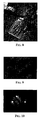
- the data stream was received by a general purposes data acquisition card of National Instrument and the pictures and the distribution map of the pressure were displayed in real time at a frame frequency of 3F/s on the monitor of a PC.
- a particularly interesting area of application of the method and of the device of the invention is that of the optimization of the shape and of the orientation of a sail in respect to the apparent wind to enhance propulsion of the ship.
- a device to detect instrumentally the primary parameter i.e. the differential pressure of the air onto the leeward and windward faces at a significant point of a sail has also been proposed in the US Patent No. 3,763,703.
- the device consists of two capillaries, one placed close to one face and the other close to the opposite face of the sail, with their inlet oriented toward the air flow over the respective face of the sail and determining, by means of a differential measuring device the static pressure difference on the leeward face and the windward face of the sail.
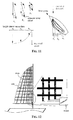
- a sail as a triangular main sail has several possibilities of adjustment of its shape to make it more or less "fat” and to increase or reduce its torsion starting from its tack on its upper leech, in proximity of its halyard corner.
- a sail for example a triangular main sail equipped with a bidimensional pressure sensor of the invention is schematically depicted in Fig. 12.
- a sail is preferably equipped with a sensor, that is with an array of pixel capacitors over both faces.
- each sensor is made of two orthogonal sets of parallel or substantially parallel plate electrodes.
- Each set of electrodes is preferably constituted by a plurality of stripes of adhesive tape incorporating a wire or a ribbon of a conducting material, applied onto the sail surface.
- the other set of electrodes is applied over the first set of electrodes interposing in each crossing zone between a plate electrode of the first set and a plate electrode of the second set a dielectric and elastically compressible pad.
- the conductor incorporated in the adhesive tape may be a ribbon of aluminum foil, eventually coated or anodized.
- the elastically compressible pads may be simple patches or pieces of a relatively soft elastic lattice or foam.
- each dielectric elastically compressible pad is constituted by a substantially round plastic cushion the opposite faces of which are elastically flexible filled with air or with another suitable gas, such that the cushion may expand or shrink depending on the pressure of the air streaming over the sail's surface.
- Each dielectric elastic pad may even comprise a flexible metal coating over both faces functioning as the plate electrodes of the relative pixel capacitor, electrically contacted by the conductive wire or metal ribbon core incorporated in the respective adhesive tape of one or of the other sets of plate electrodes of the sensor array.
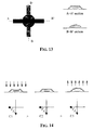
- Fig. 13 depicts a plan view and two orthogonal sections of a pixel capacitor constituted at the crossing between a row plate electrode and a column plate electrode with the interposition of an elastic gas filled cushion.
- Fig. 14 depicts schematically the variation of the equivalent capacitance that is measured under different conditions of deformation of the elastically compressible and expandable dielectric pad of each pixel capacitor.
- each elastically compressible and expandable dielectric pad is provided with an extremely thin metal coating over the opposite faces thereof, such to not to compromise the ability of the gas filled cushion faces to flex in function of the pressure difference between the internal fluid of the cushion and the outer air, is depicted in Fig. 15, including a plan view and two orthogonal cross sections of a pixel capacitor of the sensor of the invention.
- the metallization layers present on the opposite faces of the elastically compressible and expandable cushion constitute the plates of the pixel capacitor and the electrical connection of each so pre-constituted pixel capacitor by way of a respective column line and a respective row line of the array of pixel capacitors is established by contacting the plates with the conductive wire incorporated in the adhesive tape of the respective column line and row line.
- the array scnsor is coupled, as schematically depicted in Fig. 12, through connecting wires of the single lines of column and row plates to as many pins or input pads of a connector onto which may be installed a printed circuit card with the integrated circuit device for selectively and/or sequentially addressing, stimulating and reading the capacitances of the single pixel capacitors of the array.
- the elements that constitute the system for scanning, stimulating, reading and converting the read capacitance data may be installed near the tack angle of the sail, as depicted in Fig. 12.
- the integrated system may be the same that has already been described in relation to other embodiments and other applications of the sensor of the invention.
- the integrated system may read both sensor arrays placed over the opposite faces of the sail and output distribution maps of the pressure on one face and on the other face of the sail and/or eventually produce a differential pressure distribution map, by subtracting from the capacitance values of pixels of the array on the windward face of the sail the capacitance values of corresponding pixels of the array on the leeward face of the sail.
Abstract
Description
- by grounding all columns except the selected column, charge injection from the neighbouring columns, caused by CCOL, is effectively prevented;
- by grounding all the rows except the selected row, charge injection from pixels of the same column is effectively prevented.
Claims (15)
- A device for detecting the pressure exerted at different points of a flexible and/or pliable object that may assume different shapes, comprising a plurality of capacitive pressure sensors and at least a system for biasing and reading the capacitance of the sensors, characterized in that
said capacitive pressure sensors are constituted by two orthogonal sets of parallel or substantially parallel electrodes spaced, at least at each crossing between an electrode of one set and an electrode of the other set, by an elastically compressible dielectric, constituting an array of pressure sensing pixel capacitors;
said system for biasing and reading the capacitance comprising column plate electrode selection circuits and row plate electrode selection circuits and a logic circuit for sequentially scanning said pixel capacitors and outputting pixel values of the pressure for reconstructing a distribution map of the pressure over the area of said array. - The device of claim 1, characterized in that each of said two orthogonal sets of parallel electrodes is realized in form of a fabric constituted by weft oriented threads of dielectric material and warp oriented threads alternately of a conducting material, and of a dielectric material or viceversa, said threads of conducting material constituting said parallel electrodes of the set, two fabrics being fastened onto opposite faces of an elastically compressible layer of a dielectric material.
- The device of claim 1, characterized in that each of said two orthogonal sets of parallel electrodes is realized in form of parallel stripes of conductive paint applied onto a respective face of a dielectric layer or multilayer comprising at least an elastically compressible layer.
- The device of claim 1, characterized in that each of said two orthogonal sets of parallel electrodes, is constituted by a plurality of stripes of adhesive tape incorporating a thread or ribbon of conductive material laid the surface of said flexible and/or pliable object; the other set of electrodes being laid over the first set of electrodes interposing in each crossing zone between an electrode of one set and an electrode of the other set an elastically compressible dielectric pad.
- The device of claim 4, characterized in that each of said dielectric pads has a metal coating on both faces contacted by said thread or ribbon of conductive material of the respective adhesive tape of one or of the other set of electrodes.
- The device according to claim 4 or 5, characterized in that said elastically compressible dielectric pad is a gas filled cushion, the opposite faces of which elastically swell or shrink depending on the pressure difference between the filling gas of the cushion and the outside air.
- The device according to claim 4, 5, or 6, characterized in that the flexible and pliable object is a sail and said sets of column plate electrodes and row plate electrodes spaced at crossings by said elastically compressible dielectric forming said array of pressure sensing pixel capacitors are present on both faces of the sail.
- A bidimensional pressure sensor for producing pictures of the distribution map of the pressure over a surface of a flexible and/or pliable object capable of assuming different shapes, comprises two orthogonal sets of parallel or almost parallel electrodes spaced, at least in correspondence of the crossing zones between electrodes belonging to one set and electrodes belonging to the other set, by an elastically compressible dielectric, constituting an array of pressure sensing pixel capacitors, readable by sequentially scanning the pixels of the crossing zones of a selected column plate electrode of one set with a selected row plate electrode of the other set.
- The bidimensional pressure sensor of claim 8, characterized in that each of said two orthogonal sets of parallel electrodes is realized in form of a fabric constituted by weft oriented threads of dielectric material and warp oriented threads alternately of a conducting material, and of a dielectric material or viceversa, said threads of conducting material constituting said parallel electrodes of the set, two fabrics being fastened onto opposite faces of an elastically compressible layer of a dielectric material.
- The bidimensional pressure sensor of claim 8, characterized in that each of said two orthogonal sets of parallel electrodes is realized in form of parallel stripes of conductive paint applied onto a respective face of a dielectric layer or multilayer comprising at least an elastically compressible layer.
- The bidimensional pressure sensor of claim 8, characterized in that each of said two orthogonal sets of parallel or almost parallel electrodes, is constituted by a plurality of stripes of adhesive tape incorporating a thread or ribbon of conductive material laid the surface of said flexible and/or pliable object; the other set of electrodes being laid over the first set of electrodes interposing in each crossing zone between an electrode of one set and an electrode of the other set an elastically compressible dielectric pad.
- The bidimensional pressure sensor of claim 11, characterized in that each of said dielectric pads has a metal coating on both faces contacted by said thrcad or ribbon of conductive material of the respective adhesive tape of one or of the other set of electrodes.
- The bidimensional pressure sensor of claim 11 or 12, characterized in that said elastically compressible dielectric pad is a gas filled cushion, the opposite faces of which elastically swell or shrink depending on the pressure difference between the filling gas of the cushion and the outside air.
- A method of trimming a sail for maximizing the net pressure acting onto the windward face of the sail based on instrumentally measuring the pressure, characterized in that the pressure and its distribution map over the sail surface is monitored by producing in a real time mode pictures of the distribution map and of the value of the pressure over the whole or a significant portion of the sail surface on a graphic display monitor, reconstructed from data of pressure measurements carried out by scanning pixel by pixel an array of pressure sensing pixel capacitors realized on the surface of sail according to one of claims 5, 6 and 7.
- The method of claim 14, characterized in that an array of pressure sensing pixel capacitors is realized on both faces of the sail for producing pictures of the distribution map of the differential pressure of the air on the windward and on the leeward face of the sail.
Priority Applications (3)
| Application Number | Priority Date | Filing Date | Title |
|---|---|---|---|
| DE60011445T DE60011445D1 (en) | 2000-11-28 | 2000-11-28 | Textile-type capacitive pressure sensor and method for imaging the pressure exerted on points on a surface of a flexible and flexible object, in particular a sail |
| EP00830779A EP1211633B1 (en) | 2000-11-28 | 2000-11-28 | Texile-like capacitive pressure sensor and method of mapping the pressure exerted at points of a surface of a flexible and pliable object, particularly of a sail |
| US09/996,070 US6826968B2 (en) | 2000-11-28 | 2001-11-28 | Textile-like capacitive pressure sensor and method of mapping the pressure exerted at points of a surface of a flexible and pliable object, particularly of a sail |
Applications Claiming Priority (1)
| Application Number | Priority Date | Filing Date | Title |
|---|---|---|---|
| EP00830779A EP1211633B1 (en) | 2000-11-28 | 2000-11-28 | Texile-like capacitive pressure sensor and method of mapping the pressure exerted at points of a surface of a flexible and pliable object, particularly of a sail |
Publications (2)
| Publication Number | Publication Date |
|---|---|
| EP1211633A1 true EP1211633A1 (en) | 2002-06-05 |
| EP1211633B1 EP1211633B1 (en) | 2004-06-09 |
Family
ID=8175567
Family Applications (1)
| Application Number | Title | Priority Date | Filing Date |
|---|---|---|---|
| EP00830779A Expired - Lifetime EP1211633B1 (en) | 2000-11-28 | 2000-11-28 | Texile-like capacitive pressure sensor and method of mapping the pressure exerted at points of a surface of a flexible and pliable object, particularly of a sail |
Country Status (3)
| Country | Link |
|---|---|
| US (1) | US6826968B2 (en) |
| EP (1) | EP1211633B1 (en) |
| DE (1) | DE60011445D1 (en) |
Cited By (39)
| Publication number | Priority date | Publication date | Assignee | Title |
|---|---|---|---|---|
| WO2004001662A2 (en) * | 2002-06-25 | 2003-12-31 | 3M Innovative Properties Company | Touch sensor |
| EP1605240A1 (en) * | 2004-06-09 | 2005-12-14 | ETH Zürich, ETH Transfer | Textile pressure sensor |
| WO2006040781A2 (en) * | 2004-10-14 | 2006-04-20 | Neopress S.R.L. | Sensor for measuring phisical quantities based on the detection of the variation of an electrical parameter, and method for its fabrication |
| WO2007094993A1 (en) * | 2006-02-10 | 2007-08-23 | Milliken & Company | Flexible capacitive sensor |
| FR2897936A1 (en) * | 2006-02-24 | 2007-08-31 | Emmanuel Garcia | Double piezoelectric sensor for yachting, has pellets and toothed plates with electrical connection terminal permitting to connect pellets and plates to acquisition system, where sensor has less thickness |
| WO2007130771A2 (en) * | 2006-05-02 | 2007-11-15 | Apple Inc. | Multipoint touch surface controller |
| US7301351B2 (en) | 2006-02-10 | 2007-11-27 | Milliken & Company | Printed capacitive sensor |
| US7368921B2 (en) | 2006-02-10 | 2008-05-06 | Milliken & Company | Printed capacitive sensor |
| EP1947436A1 (en) * | 2005-09-12 | 2008-07-23 | The University of Tokyo | Module for tactile sensor and method for packaging tactile sensor |
| WO2008102308A2 (en) * | 2007-02-23 | 2008-08-28 | Philips Intellectual Property & Standards Gmbh | Shear force and pressure measurement in wearable textiles |
| DE102008007353A1 (en) | 2008-01-29 | 2009-07-30 | Iris-Gmbh Infrared & Intelligent Sensors | Person identification device for use in area of e.g. automatic teller machine, has evaluation unit generating comparison result signal based on similarity between detected person-individual characteristics and stored characteristics |
| US7719007B2 (en) | 2008-04-30 | 2010-05-18 | Milliken & Company | Flexible electroluminescent capacitive sensor |
| WO2010142071A1 (en) * | 2009-06-08 | 2010-12-16 | Tex-Ray Industrial Co., Ltd. | Fabric connector for sensing object proximity |
| DE102004025237B4 (en) * | 2003-09-08 | 2011-07-07 | Textilforschungsinstitut Thüringen-Vogtland e.V., 07973 | Textile pressure and tension sensor |
| CN102165297A (en) * | 2008-11-21 | 2011-08-24 | 鹰野株式会社 | Capacitive dynamic quantity sensor element and dynamic quantity sensor |
| WO2012095608A2 (en) | 2011-01-13 | 2012-07-19 | LAVARENNE, Anna | Device for measuring pressure from a flexible, pliable, and/or extensible object made from a textile material comprising a measurement device |
| WO2012101374A1 (en) | 2011-01-25 | 2012-08-02 | Francis Cannard | Device intended for measuring pressure from a flexible, foldable, and/or extendable object made of a textile material and comprising a measurement device |
| WO2011111021A3 (en) * | 2010-03-12 | 2012-11-29 | Enhanced Surface Dynamics, Inc. | System and method for rapid data collection from pressure sensors in a pressure sensing system |
| WO2013034745A1 (en) * | 2011-09-07 | 2013-03-14 | Universität Kassel | Movable, sensitive surface |
| US8416209B2 (en) | 2004-05-06 | 2013-04-09 | Apple Inc. | Multipoint touchscreen |
| US8432371B2 (en) | 2006-06-09 | 2013-04-30 | Apple Inc. | Touch screen liquid crystal display |
| US8493330B2 (en) | 2007-01-03 | 2013-07-23 | Apple Inc. | Individual channel phase delay scheme |
| TWI410848B (en) * | 2009-08-28 | 2013-10-01 | Elan Microelectronics Corp | Detection Circuit and Method of Capacitive Touchpad |
| US8552989B2 (en) | 2006-06-09 | 2013-10-08 | Apple Inc. | Integrated display and touch screen |
| US8654083B2 (en) | 2006-06-09 | 2014-02-18 | Apple Inc. | Touch screen liquid crystal display |
| US8743300B2 (en) | 2010-12-22 | 2014-06-03 | Apple Inc. | Integrated touch screens |
| DE102007020247B4 (en) * | 2006-12-14 | 2014-12-04 | Textilforschungsinstitut Thüringen-Vogtland e.V. | Device for measuring a contact pressure of a medical compression means, in particular a compression stocking or bandage |
| CN104458075A (en) * | 2014-12-31 | 2015-03-25 | 中国矿业大学 | Stress distribution monitoring device and method |
| GB2519110A (en) * | 2013-10-09 | 2015-04-15 | Nokia Technologies Oy | An apparatus and associated methods for analyte detection |
| FR3026841A1 (en) * | 2014-10-02 | 2016-04-08 | Valeo Vision | CAPACITIVE SENSOR |
| EP2343805A3 (en) * | 2010-01-05 | 2016-12-07 | Robert Bosch GmbH | Sensitive area element and assembly comprising sensitive area elements |
| US9671304B2 (en) | 2011-07-13 | 2017-06-06 | Enhanced Surface Dynamics, Inc. | Methods and systems for the manufacture and initiation of a pressure detection mat |
| US9710095B2 (en) | 2007-01-05 | 2017-07-18 | Apple Inc. | Touch screen stack-ups |
| US9788791B2 (en) | 2005-06-07 | 2017-10-17 | Koninklijke Philips N.V. | Patient monitoring system and method |
| US9939968B2 (en) | 2014-03-03 | 2018-04-10 | Samsung Display Co., Ltd. | Touch panel and display apparatus including the same |
| WO2018120212A1 (en) * | 2016-12-30 | 2018-07-05 | 深圳配天智能技术研究院有限公司 | Pressure array detection device, corresponding method, and pulse diagnosis detection device |
| US10282010B2 (en) | 2014-07-25 | 2019-05-07 | Samsung Display Co., Ltd. | Display device |
| EP3492927A1 (en) * | 2017-11-30 | 2019-06-05 | Airbus Operations SAS | Sailing vessel comprising an aerodynamic profile and a system for determining characteristics of an incident air flow on a leading edge of the aerodynamic profile |
| CN113939724A (en) * | 2019-01-30 | 2022-01-14 | 海维动力控股有限公司 | Stretchable bidirectional capacitive pressure sensor and use method thereof |
Families Citing this family (94)
| Publication number | Priority date | Publication date | Assignee | Title |
|---|---|---|---|---|
| JP3983638B2 (en) * | 2002-09-24 | 2007-09-26 | ニッタ株式会社 | Sensor sheet |
| JP4098215B2 (en) * | 2003-10-29 | 2008-06-11 | アイシン精機株式会社 | Human body detection device for vehicle |
| DE102004022373B4 (en) * | 2004-05-06 | 2006-03-16 | W.E.T. Automotive Systems Ag | Multilayer sewn system |
| US7204162B2 (en) * | 2004-11-23 | 2007-04-17 | Delphi Technologies, Inc. | Capacitive strain gauge |
| KR100608927B1 (en) * | 2005-05-26 | 2006-08-08 | 한국과학기술원 | Electrode layer for capacitor, method of manufacturing the electrode layer, unit sensor using the electrode layer and tactile sensor using the unit sensor |
| US8127623B2 (en) * | 2005-05-18 | 2012-03-06 | Pressure Profile Systems Inc. | Capacitive tactile tile sensor |
| US7430925B2 (en) * | 2005-05-18 | 2008-10-07 | Pressure Profile Systems, Inc. | Hybrid tactile sensor |
| US20090286055A1 (en) * | 2005-11-08 | 2009-11-19 | Behnam Pourdeyhimi | Methods and Devices for Providing Flexible Electronics |
| US7712373B2 (en) * | 2006-03-03 | 2010-05-11 | Nagle H Troy | Sensor device for real-time monitoring or relative movement using capacitive fabric sensors |
| KR20090017527A (en) * | 2006-04-25 | 2009-02-18 | 엑스센서 테크놀로지 코포레이션 | Capacitive node measurement in a capacitive matrix pressure transducer |
| ES2294934B1 (en) * | 2006-07-06 | 2008-11-16 | Fundacio Privada Per A La Innovacio Textil D'igualada | TEXTILE SENSOR OF PRESSURE AND / OR TENSION AND / OR TORSION EFFORTS. |
| US8836647B2 (en) | 2006-09-26 | 2014-09-16 | Koninklijke Philips N.V. | Non-linear resistive touch sensor |
| US20080098941A1 (en) * | 2006-10-30 | 2008-05-01 | Malcolm Duane Groves | Apparatus to determine the optimum setting of a boat sail |
| US7509884B2 (en) * | 2007-02-01 | 2009-03-31 | Nitta Corporation | Sensor sheet |
| JP2010519948A (en) * | 2007-02-28 | 2010-06-10 | コーニンクレッカ フィリップス エレクトロニクス エヌ ヴィ | System and method for acquiring physiological data of a patient |
| US7788981B2 (en) * | 2007-03-16 | 2010-09-07 | Csem Centre Suisse D'electronique Et De Microtechnique Sa - Recherche Et Developpement | Pressure measurement device and system, and method for manufacturing and using the same |
| WO2008119188A1 (en) * | 2007-04-03 | 2008-10-09 | Sailmeter Inc. | Pressure sensing method and system for flexible aerodynamic surfaces |
| EP2150791B1 (en) * | 2007-04-23 | 2016-03-16 | Given Imaging (Los Angeles) LLC | Suspended membrane pressure sensing array |
| EP2148838B1 (en) * | 2007-05-24 | 2017-03-01 | Digital Biosystems | Electrowetting based digital microfluidics |
| WO2009030067A1 (en) * | 2007-09-04 | 2009-03-12 | Chang-Ming Yang | Cloth capable of forming electronic components |
| JP5416904B2 (en) * | 2008-02-12 | 2014-02-12 | 株式会社東芝 | Pressure sensor and robot hand system |
| US8186231B2 (en) * | 2008-09-22 | 2012-05-29 | Intel Corporatioon | Method and apparatus for scanning a textile |
| US9758907B2 (en) * | 2008-09-22 | 2017-09-12 | Intel Corporation | Method and apparatus for attaching chip to a textile |
| US8266971B1 (en) | 2008-11-25 | 2012-09-18 | Randall Jones | Surface force distribution sensor by frequency-domain multiplexing |
| EP3398507A1 (en) | 2009-01-24 | 2018-11-07 | Changming Yang | Sensing device |
| RU2390628C1 (en) * | 2009-04-06 | 2010-05-27 | Олег Марсимович Мирсаетов | Method of oil-field management |
| WO2010119441A2 (en) * | 2009-04-13 | 2010-10-21 | Wellsense Technologies | System and method for preventing decubitus ulcers |
| US8272276B2 (en) * | 2009-05-06 | 2012-09-25 | Xsensor Technology Corporation | Dielectric textured elastomer in a pressure mapping system |
| US9323398B2 (en) | 2009-07-10 | 2016-04-26 | Apple Inc. | Touch and hover sensing |
| US8621942B2 (en) * | 2009-08-03 | 2014-01-07 | Atmel Corporation | Force sensor with compressible electrode |
| US8544336B2 (en) * | 2009-11-26 | 2013-10-01 | Xsensor Technology Corporation | Sealed conductive grid capacitive pressure sensor |
| US8393229B2 (en) * | 2010-02-24 | 2013-03-12 | The Hong Kong Research Institute Of Textiles And Apparel Limited | Soft pressure sensing device |
| CA2734427C (en) | 2010-03-19 | 2018-05-08 | Xavier Pierre-Emmanuel Saynac | Systems and methods for determining the location and pressure of a touchload applied to a touchpad |
| WO2011137566A1 (en) | 2010-05-07 | 2011-11-10 | Yang Changming | Method and system for generating physiological signals with fabric capacitive sensors |
| US9268431B2 (en) | 2010-08-27 | 2016-02-23 | Apple Inc. | Touch and hover switching |
| US9459736B2 (en) * | 2010-10-12 | 2016-10-04 | Parade Technologies, Ltd. | Flexible capacitive sensor array |
| US9454268B2 (en) * | 2010-10-12 | 2016-09-27 | Parade Technologies, Ltd. | Force sensing capacitive hybrid touch sensor |
| BR112013021275A2 (en) * | 2011-02-24 | 2018-06-05 | Enhanced Surface Dynamics Inc | operable pressure wound prevention system to motivate at least one caregiver to reposition an individual at risk of developing a pressure wound |
| US9271665B2 (en) * | 2011-05-20 | 2016-03-01 | The Regents Of The University Of California | Fabric-based pressure sensor arrays and methods for data analysis |
| EP2575084A1 (en) * | 2011-09-30 | 2013-04-03 | Nxp B.V. | Security token and authentication system |
| US9095058B2 (en) * | 2011-11-30 | 2015-07-28 | Touchsensor Technologies, Llc | Electrode structure with spatial interpolation for capacitive touch panel |
| WO2013112828A1 (en) * | 2012-01-26 | 2013-08-01 | Huntleigh Technology Limited | Pressure measurement systems and methods with moisture vapor control |
| DE102012103856B4 (en) * | 2012-02-16 | 2016-09-29 | Peter Seitz | Textile pressure sensor |
| US9086768B2 (en) | 2012-04-30 | 2015-07-21 | Apple Inc. | Mitigation of parasitic capacitance |
| US9201547B2 (en) | 2012-04-30 | 2015-12-01 | Apple Inc. | Wide dynamic range capacitive sensing |
| US8913021B2 (en) * | 2012-04-30 | 2014-12-16 | Apple Inc. | Capacitance touch near-field—far field switching |
| US9588582B2 (en) | 2013-09-17 | 2017-03-07 | Medibotics Llc | Motion recognition clothing (TM) with two different sets of tubes spanning a body joint |
| US9582072B2 (en) | 2013-09-17 | 2017-02-28 | Medibotics Llc | Motion recognition clothing [TM] with flexible electromagnetic, light, or sonic energy pathways |
| US20140037909A1 (en) * | 2012-08-01 | 2014-02-06 | Massachusetts Institute Of Technology | Actuation and Control of Stamp Deformation in Microcontact Printing |
| TWI497384B (en) * | 2012-12-28 | 2015-08-21 | Egalax Empia Technology Inc | Touch sensing circuit, apparatus, and system and operating method thereof |
| US9322121B2 (en) | 2013-02-28 | 2016-04-26 | Regents Of The University Of Minnesota | Stitched stretch sensor |
| FR3004551A1 (en) * | 2013-04-15 | 2014-10-17 | Fogale Nanotech | MULTIZONE CAPACITIVE DETECTION METHOD, DEVICE AND APPARATUS USING THE METHOD |
| US8874396B1 (en) * | 2013-06-28 | 2014-10-28 | Cypress Semiconductor Corporation | Injected touch noise analysis |
| ES2485617B1 (en) * | 2013-09-16 | 2015-04-06 | Sensing Tex, S.L. | Piezo-resistive textile sensor and heart and / or respiratory rhythm detection system |
| US9933879B2 (en) | 2013-11-25 | 2018-04-03 | Apple Inc. | Reconfigurable circuit topology for both self-capacitance and mutual capacitance sensing |
| FR3015714B1 (en) * | 2013-12-19 | 2017-04-21 | Dav | MAN INTERFACE MACHINE FOR CONTROLLING AT LEAST TWO FUNCTIONS OF A MOTOR VEHICLE |
| US20170361045A1 (en) * | 2014-06-27 | 2017-12-21 | Resmed Limited | Auto-fit mask |
| FR3023914B1 (en) * | 2014-07-18 | 2017-07-21 | Feetme | NETWORK SYSTEM WITH CAPACITIVE PRESSURE AND SHEAR CAPACITIVE SENSOR CELLS AND METHOD OF MANUFACTURE |
| US9504620B2 (en) | 2014-07-23 | 2016-11-29 | American Sterilizer Company | Method of controlling a pressurized mattress system for a support structure |
| US9799177B2 (en) | 2014-09-23 | 2017-10-24 | Intel Corporation | Apparatus and methods for haptic covert communication |
| EP3201744B1 (en) | 2014-09-30 | 2022-06-08 | Apple Inc. | Fabric sensing device |
| US9627804B2 (en) | 2014-12-19 | 2017-04-18 | Intel Corporation | Snap button fastener providing electrical connection |
| JP6572420B2 (en) * | 2015-03-05 | 2019-09-11 | 株式会社槌屋 | Conductive fabric and pressure sensor using conductive fabric |
| US10082913B2 (en) * | 2015-05-10 | 2018-09-25 | Microsoft Technology Licensing, Llc | Embroidered sensor assembly |
| CN105067160B (en) * | 2015-07-23 | 2017-10-03 | 东南大学 | Pliable pressure sensor based on graphene oxide sponge |
| US10470711B2 (en) | 2015-07-31 | 2019-11-12 | Wiivv Wearables Inc. | Electronic sensor system for use with footwear |
| KR102432009B1 (en) * | 2015-09-03 | 2022-08-12 | 엘지이노텍 주식회사 | Pressure sensor |
| US10372259B2 (en) * | 2016-02-19 | 2019-08-06 | Synaptics Incorporated | Transcapacitive touch and force sensing in an input device |
| US10054503B2 (en) * | 2016-03-11 | 2018-08-21 | Microsoft Technology Licensing, Llc | Force sensor |
| CN107290082B (en) * | 2016-04-11 | 2019-12-20 | 刘垚 | Capacitive touch sensor |
| US10025440B2 (en) | 2016-07-13 | 2018-07-17 | Stmicroelectronics Asia Pacific Pte Ltd | Correlated data acquisition among different touch sensors |
| CN106200156B (en) * | 2016-09-18 | 2019-06-18 | 厦门天马微电子有限公司 | A kind of display panel and electronic equipment |
| WO2018081038A1 (en) * | 2016-10-24 | 2018-05-03 | University Of Louisville Research Foundation, Inc. | Anisotropic conductive threads for electrical connections in soft electronics |
| CA3010114C (en) | 2016-10-25 | 2018-09-18 | Studio 1 Holdings Inc. | Flexible conductive apparatus and systems for detecting pressure |
| US10492734B2 (en) | 2016-11-04 | 2019-12-03 | Wellsense, Inc. | Patient visualization system |
| US11083418B2 (en) | 2016-11-04 | 2021-08-10 | Wellsense, Inc. | Patient visualization system |
| DE102017100791B4 (en) * | 2017-01-17 | 2018-09-06 | Pilz Gmbh & Co. Kg | Multi-layer, tactile sensor with fastening means |
| US10260975B2 (en) * | 2017-03-17 | 2019-04-16 | Politecnico Di Milano | Device for pressure measurements on yacht sails |
| AU2017201840B2 (en) * | 2017-03-17 | 2022-05-12 | Fondazione Cariplo | A device for pressure measurements on yacht sails |
| US10180721B2 (en) | 2017-06-14 | 2019-01-15 | Apple Inc. | Fabric-based devices with force sensing |
| US10233571B1 (en) * | 2017-12-26 | 2019-03-19 | GM Global Technology Operations LLC | Multi-functional textiles with integrated sensing and control elements |
| CN111516617A (en) * | 2019-02-01 | 2020-08-11 | 佛吉亚(中国)投资有限公司 | Touch module for vehicle interior, interior and vehicle comprising same |
| US11460364B1 (en) * | 2019-02-07 | 2022-10-04 | Starrycom Sensing Technologies Inc. | Multiplexed inductive tactile sensor array |
| CN110849508B (en) * | 2019-11-29 | 2021-12-24 | 上海交通大学 | Flexible pressure sensor based on discrete contact structure and preparation method thereof |
| CN115135980A (en) * | 2019-12-24 | 2022-09-30 | 麻省理工学院 | Omnidirectional soft capacitive touch sensor and use method thereof |
| US11193846B2 (en) * | 2020-03-16 | 2021-12-07 | TE Connectivity Services Gmbh | Compressible element for a sensor assembly |
| CN111489645B (en) * | 2020-04-23 | 2022-06-24 | 京东方科技集团股份有限公司 | Display substrate, manufacturing method thereof and display device |
| CN112067174A (en) * | 2020-05-28 | 2020-12-11 | 北京机械设备研究所 | Flexible capacitive touch sensor array |
| IT202000018331A1 (en) * | 2020-07-28 | 2022-01-28 | Koyre S R L | STRESS DETECTION SYSTEM IN A FLEXIBLE TWO-DIMENSIONAL STRUCTURE |
| US11772760B2 (en) | 2020-12-11 | 2023-10-03 | William T. Myslinski | Smart wetsuit, surfboard and backpack system |
| GB2602155A (en) * | 2020-12-21 | 2022-06-22 | Graphene Trace Ltd | Textile-based sensing device |
| DE102021100796A1 (en) | 2021-01-15 | 2022-07-21 | Sebastian Brato | Textile for weight determination |
| CN113232031A (en) * | 2021-01-20 | 2021-08-10 | 北京航空航天大学 | Novel electronic skin with adjustable pressure sensing range |
| CN113048974B (en) * | 2021-03-17 | 2023-09-22 | 吉林大学 | Bionic positioning device and application method thereof |
Citations (3)
| Publication number | Priority date | Publication date | Assignee | Title |
|---|---|---|---|---|
| DE3025362A1 (en) * | 1980-07-04 | 1982-01-28 | Ewald Max Christian Dipl.-Phys. 6000 Frankfurt Hennig | Force transducer |
| US4644801A (en) * | 1984-08-21 | 1987-02-24 | Cybertronics Ltd. | Surface-area pressure transducer and line-selection circuit for use therewith |
| US4827395A (en) * | 1983-04-21 | 1989-05-02 | Intelli-Tech Corporation | Manufacturing monitoring and control systems |
Family Cites Families (7)
| Publication number | Priority date | Publication date | Assignee | Title |
|---|---|---|---|---|
| DE2529475C3 (en) * | 1975-07-02 | 1981-10-08 | Ewald Max Christian Dipl.-Phys. 6000 Frankfurt Hennig | Electrical circuit arrangement for time-dependent measurement of physical quantities |
| CA1155178A (en) * | 1978-01-06 | 1983-10-11 | David Wright | Detecting and measuring the position of a break in solid formations |
| US4526043A (en) * | 1983-05-23 | 1985-07-02 | At&T Bell Laboratories | Conformable tactile sensor |
| US5010772A (en) * | 1986-04-11 | 1991-04-30 | Purdue Research Foundation | Pressure mapping system with capacitive measuring pad |
| US5532605A (en) * | 1994-10-27 | 1996-07-02 | Agr International, Inc. | Container inspection apparatus having diameter measuring means and associated method |
| US5920454A (en) * | 1997-02-11 | 1999-07-06 | Hokuriko Electric Industry Co., Ltd. | Capacitor-mounted circuit board |
| US6034864A (en) * | 1997-11-14 | 2000-03-07 | Murata Manufacturing Co., Ltd. | Multilayer capacitor |
-
2000
- 2000-11-28 EP EP00830779A patent/EP1211633B1/en not_active Expired - Lifetime
- 2000-11-28 DE DE60011445T patent/DE60011445D1/en not_active Expired - Lifetime
-
2001
- 2001-11-28 US US09/996,070 patent/US6826968B2/en not_active Expired - Lifetime
Patent Citations (3)
| Publication number | Priority date | Publication date | Assignee | Title |
|---|---|---|---|---|
| DE3025362A1 (en) * | 1980-07-04 | 1982-01-28 | Ewald Max Christian Dipl.-Phys. 6000 Frankfurt Hennig | Force transducer |
| US4827395A (en) * | 1983-04-21 | 1989-05-02 | Intelli-Tech Corporation | Manufacturing monitoring and control systems |
| US4644801A (en) * | 1984-08-21 | 1987-02-24 | Cybertronics Ltd. | Surface-area pressure transducer and line-selection circuit for use therewith |
Cited By (86)
| Publication number | Priority date | Publication date | Assignee | Title |
|---|---|---|---|---|
| WO2004001662A3 (en) * | 2002-06-25 | 2004-03-25 | 3M Innovative Properties Co | Touch sensor |
| WO2004001662A2 (en) * | 2002-06-25 | 2003-12-31 | 3M Innovative Properties Company | Touch sensor |
| DE102004025237B4 (en) * | 2003-09-08 | 2011-07-07 | Textilforschungsinstitut Thüringen-Vogtland e.V., 07973 | Textile pressure and tension sensor |
| US8928618B2 (en) | 2004-05-06 | 2015-01-06 | Apple Inc. | Multipoint touchscreen |
| US10908729B2 (en) | 2004-05-06 | 2021-02-02 | Apple Inc. | Multipoint touchscreen |
| US9035907B2 (en) | 2004-05-06 | 2015-05-19 | Apple Inc. | Multipoint touchscreen |
| US11604547B2 (en) | 2004-05-06 | 2023-03-14 | Apple Inc. | Multipoint touchscreen |
| US8982087B2 (en) | 2004-05-06 | 2015-03-17 | Apple Inc. | Multipoint touchscreen |
| US10331259B2 (en) | 2004-05-06 | 2019-06-25 | Apple Inc. | Multipoint touchscreen |
| US9454277B2 (en) | 2004-05-06 | 2016-09-27 | Apple Inc. | Multipoint touchscreen |
| US8605051B2 (en) | 2004-05-06 | 2013-12-10 | Apple Inc. | Multipoint touchscreen |
| US8416209B2 (en) | 2004-05-06 | 2013-04-09 | Apple Inc. | Multipoint touchscreen |
| US8872785B2 (en) | 2004-05-06 | 2014-10-28 | Apple Inc. | Multipoint touchscreen |
| WO2005121729A1 (en) * | 2004-06-09 | 2005-12-22 | Eth Zürich Eth Transfer | Textile capacitive pressure sensor |
| EP1605240A1 (en) * | 2004-06-09 | 2005-12-14 | ETH Zürich, ETH Transfer | Textile pressure sensor |
| WO2006040781A2 (en) * | 2004-10-14 | 2006-04-20 | Neopress S.R.L. | Sensor for measuring phisical quantities based on the detection of the variation of an electrical parameter, and method for its fabrication |
| WO2006040781A3 (en) * | 2004-10-14 | 2008-01-17 | Neopress S R L | Sensor for measuring phisical quantities based on the detection of the variation of an electrical parameter, and method for its fabrication |
| US9788791B2 (en) | 2005-06-07 | 2017-10-17 | Koninklijke Philips N.V. | Patient monitoring system and method |
| EP1947436A1 (en) * | 2005-09-12 | 2008-07-23 | The University of Tokyo | Module for tactile sensor and method for packaging tactile sensor |
| EP1947436A4 (en) * | 2005-09-12 | 2014-04-02 | Univ Tokyo | Module for tactile sensor and method for packaging tactile sensor |
| US7395717B2 (en) | 2006-02-10 | 2008-07-08 | Milliken & Company | Flexible capacitive sensor |
| US7578195B2 (en) | 2006-02-10 | 2009-08-25 | Milliken & Company | Capacitive sensor |
| GB2448453A (en) * | 2006-02-10 | 2008-10-15 | Milliken & Co | Flexible capacitive sensor |
| US7368921B2 (en) | 2006-02-10 | 2008-05-06 | Milliken & Company | Printed capacitive sensor |
| US7301351B2 (en) | 2006-02-10 | 2007-11-27 | Milliken & Company | Printed capacitive sensor |
| WO2007094993A1 (en) * | 2006-02-10 | 2007-08-23 | Milliken & Company | Flexible capacitive sensor |
| FR2897936A1 (en) * | 2006-02-24 | 2007-08-31 | Emmanuel Garcia | Double piezoelectric sensor for yachting, has pellets and toothed plates with electrical connection terminal permitting to connect pellets and plates to acquisition system, where sensor has less thickness |
| CN101479692B (en) * | 2006-05-02 | 2011-07-27 | 苹果公司 | Multipoint touch surface controller |
| AU2011200537B2 (en) * | 2006-05-02 | 2013-10-31 | Apple Inc. | Multipoint touch surface controller |
| US10915207B2 (en) | 2006-05-02 | 2021-02-09 | Apple Inc. | Multipoint touch surface controller |
| GB2475631A (en) * | 2006-05-02 | 2011-05-25 | Apple Inc | Multipoint touch surface controller |
| WO2007130771A2 (en) * | 2006-05-02 | 2007-11-15 | Apple Inc. | Multipoint touch surface controller |
| JP2018110041A (en) * | 2006-05-02 | 2018-07-12 | アップル インコーポレイテッド | Multipoint touch surface controller |
| GB2451973B (en) * | 2006-05-02 | 2011-04-27 | Apple Inc | Multipoint touch surface controller |
| AU2007248332B2 (en) * | 2006-05-02 | 2011-03-10 | Apple Inc. | Multipoint touch surface controller |
| CN101989162B (en) * | 2006-05-02 | 2015-01-21 | 苹果公司 | Multipoint touch surface controller |
| WO2007130771A3 (en) * | 2006-05-02 | 2008-02-28 | Apple Inc | Multipoint touch surface controller |
| US11853518B2 (en) | 2006-05-02 | 2023-12-26 | Apple Inc. | Multipoint touch surface controller |
| GB2451973A (en) * | 2006-05-02 | 2009-02-18 | Apple Inc | Multipoint touch surface controller |
| GB2475631B (en) * | 2006-05-02 | 2011-10-05 | Apple Inc | Multipoint touch surface controller |
| US11886651B2 (en) | 2006-06-09 | 2024-01-30 | Apple Inc. | Touch screen liquid crystal display |
| US11175762B2 (en) | 2006-06-09 | 2021-11-16 | Apple Inc. | Touch screen liquid crystal display |
| US8654083B2 (en) | 2006-06-09 | 2014-02-18 | Apple Inc. | Touch screen liquid crystal display |
| US10976846B2 (en) | 2006-06-09 | 2021-04-13 | Apple Inc. | Touch screen liquid crystal display |
| US9575610B2 (en) | 2006-06-09 | 2017-02-21 | Apple Inc. | Touch screen liquid crystal display |
| US8552989B2 (en) | 2006-06-09 | 2013-10-08 | Apple Inc. | Integrated display and touch screen |
| US8451244B2 (en) | 2006-06-09 | 2013-05-28 | Apple Inc. | Segmented Vcom |
| US8432371B2 (en) | 2006-06-09 | 2013-04-30 | Apple Inc. | Touch screen liquid crystal display |
| US10191576B2 (en) | 2006-06-09 | 2019-01-29 | Apple Inc. | Touch screen liquid crystal display |
| US9268429B2 (en) | 2006-06-09 | 2016-02-23 | Apple Inc. | Integrated display and touch screen |
| US9244561B2 (en) | 2006-06-09 | 2016-01-26 | Apple Inc. | Touch screen liquid crystal display |
| DE102007020247B4 (en) * | 2006-12-14 | 2014-12-04 | Textilforschungsinstitut Thüringen-Vogtland e.V. | Device for measuring a contact pressure of a medical compression means, in particular a compression stocking or bandage |
| US8493330B2 (en) | 2007-01-03 | 2013-07-23 | Apple Inc. | Individual channel phase delay scheme |
| US9710095B2 (en) | 2007-01-05 | 2017-07-18 | Apple Inc. | Touch screen stack-ups |
| US10521065B2 (en) | 2007-01-05 | 2019-12-31 | Apple Inc. | Touch screen stack-ups |
| WO2008102308A2 (en) * | 2007-02-23 | 2008-08-28 | Philips Intellectual Property & Standards Gmbh | Shear force and pressure measurement in wearable textiles |
| WO2008102308A3 (en) * | 2007-02-23 | 2008-10-23 | Philips Intellectual Property | Shear force and pressure measurement in wearable textiles |
| DE102008007353A1 (en) | 2008-01-29 | 2009-07-30 | Iris-Gmbh Infrared & Intelligent Sensors | Person identification device for use in area of e.g. automatic teller machine, has evaluation unit generating comparison result signal based on similarity between detected person-individual characteristics and stored characteristics |
| US7719007B2 (en) | 2008-04-30 | 2010-05-18 | Milliken & Company | Flexible electroluminescent capacitive sensor |
| CN102165297A (en) * | 2008-11-21 | 2011-08-24 | 鹰野株式会社 | Capacitive dynamic quantity sensor element and dynamic quantity sensor |
| WO2010142071A1 (en) * | 2009-06-08 | 2010-12-16 | Tex-Ray Industrial Co., Ltd. | Fabric connector for sensing object proximity |
| TWI410848B (en) * | 2009-08-28 | 2013-10-01 | Elan Microelectronics Corp | Detection Circuit and Method of Capacitive Touchpad |
| EP2343805A3 (en) * | 2010-01-05 | 2016-12-07 | Robert Bosch GmbH | Sensitive area element and assembly comprising sensitive area elements |
| CN102892354A (en) * | 2010-03-12 | 2013-01-23 | 茵汉斯瑟菲斯动力公司 | System and method for rapid data collection from pressure sensors in pressure sensing system |
| WO2011111021A3 (en) * | 2010-03-12 | 2012-11-29 | Enhanced Surface Dynamics, Inc. | System and method for rapid data collection from pressure sensors in a pressure sensing system |
| US8743300B2 (en) | 2010-12-22 | 2014-06-03 | Apple Inc. | Integrated touch screens |
| US9146414B2 (en) | 2010-12-22 | 2015-09-29 | Apple Inc. | Integrated touch screens |
| US8804056B2 (en) | 2010-12-22 | 2014-08-12 | Apple Inc. | Integrated touch screens |
| US9727193B2 (en) | 2010-12-22 | 2017-08-08 | Apple Inc. | Integrated touch screens |
| US9025090B2 (en) | 2010-12-22 | 2015-05-05 | Apple Inc. | Integrated touch screens |
| US10409434B2 (en) | 2010-12-22 | 2019-09-10 | Apple Inc. | Integrated touch screens |
| US9448127B2 (en) | 2011-01-13 | 2016-09-20 | Francis Cannard | Device for measuring pressure from a flexible, pliable, and/or extensible object made from a textile material comprising a measurement device |
| WO2012095608A2 (en) | 2011-01-13 | 2012-07-19 | LAVARENNE, Anna | Device for measuring pressure from a flexible, pliable, and/or extensible object made from a textile material comprising a measurement device |
| WO2012101374A1 (en) | 2011-01-25 | 2012-08-02 | Francis Cannard | Device intended for measuring pressure from a flexible, foldable, and/or extendable object made of a textile material and comprising a measurement device |
| US9671304B2 (en) | 2011-07-13 | 2017-06-06 | Enhanced Surface Dynamics, Inc. | Methods and systems for the manufacture and initiation of a pressure detection mat |
| WO2013034745A1 (en) * | 2011-09-07 | 2013-03-14 | Universität Kassel | Movable, sensitive surface |
| US10203303B2 (en) | 2013-10-09 | 2019-02-12 | Nokia Technologies Oy | Apparatus and associated methods for analyte detection |
| GB2519110B (en) * | 2013-10-09 | 2018-04-18 | Nokia Technologies Oy | An apparatus and associated methods for analyte detection |
| GB2519110A (en) * | 2013-10-09 | 2015-04-15 | Nokia Technologies Oy | An apparatus and associated methods for analyte detection |
| US9939968B2 (en) | 2014-03-03 | 2018-04-10 | Samsung Display Co., Ltd. | Touch panel and display apparatus including the same |
| US10282010B2 (en) | 2014-07-25 | 2019-05-07 | Samsung Display Co., Ltd. | Display device |
| FR3026841A1 (en) * | 2014-10-02 | 2016-04-08 | Valeo Vision | CAPACITIVE SENSOR |
| CN104458075A (en) * | 2014-12-31 | 2015-03-25 | 中国矿业大学 | Stress distribution monitoring device and method |
| WO2018120212A1 (en) * | 2016-12-30 | 2018-07-05 | 深圳配天智能技术研究院有限公司 | Pressure array detection device, corresponding method, and pulse diagnosis detection device |
| EP3492927A1 (en) * | 2017-11-30 | 2019-06-05 | Airbus Operations SAS | Sailing vessel comprising an aerodynamic profile and a system for determining characteristics of an incident air flow on a leading edge of the aerodynamic profile |
| CN113939724A (en) * | 2019-01-30 | 2022-01-14 | 海维动力控股有限公司 | Stretchable bidirectional capacitive pressure sensor and use method thereof |
Also Published As
| Publication number | Publication date |
|---|---|
| US6826968B2 (en) | 2004-12-07 |
| EP1211633B1 (en) | 2004-06-09 |
| DE60011445D1 (en) | 2004-07-15 |
| US20020121146A1 (en) | 2002-09-05 |
Similar Documents
| Publication | Publication Date | Title |
|---|---|---|
| EP1211633B1 (en) | Texile-like capacitive pressure sensor and method of mapping the pressure exerted at points of a surface of a flexible and pliable object, particularly of a sail | |
| US4640137A (en) | Tactile sensor | |
| US20090033341A1 (en) | Capacitive tactile tile sensor | |
| JPH0531540Y2 (en) | ||
| CA1272393A (en) | Electrographic touch sensor with z-axis capability | |
| US4827763A (en) | Pressure mapping system with capacitive measuring pad | |
| US7202855B2 (en) | Capacitive input device | |
| US4661655A (en) | Electrographic touch sensor and method of reducing bowed equipotential fields therein | |
| US4866412A (en) | Tactile sensor device | |
| US7430925B2 (en) | Hybrid tactile sensor | |
| US4371746A (en) | Edge terminations for impedance planes | |
| KR101192498B1 (en) | Apparatus for fingerprint sensing and other measurements | |
| CN109213369B (en) | Touch screen and OLED display panel | |
| RU1808121C (en) | Tactile sensitive element | |
| CN106840475B (en) | Flexible pressure sensing system | |
| US20110318985A1 (en) | Touch Sensor Fabric | |
| WO2005068961A1 (en) | A sensor | |
| US6011545A (en) | Multi-panel digitizer | |
| ATE51447T1 (en) | TRANSDUCER MATRIX. | |
| US4625075A (en) | Patterned conductive ink touch panel | |
| US5357194A (en) | Testing bed and apparatus including same for testing printed circuit boards and other like articles | |
| US20050134260A1 (en) | Sensor for coordinate input device | |
| US20220034738A1 (en) | Sensory array structures with two or more different sets of resolution, method of fabrication of and method of operating same | |
| US20210307170A1 (en) | Sensory array for use with artificial skin and artificial skin with sensory array, useful in robotics | |
| CN209446074U (en) | Measuring circuit |
Legal Events
| Date | Code | Title | Description |
|---|---|---|---|
| PUAI | Public reference made under article 153(3) epc to a published international application that has entered the european phase |
Free format text: ORIGINAL CODE: 0009012 |
|
| AK | Designated contracting states |
Kind code of ref document: A1 Designated state(s): AT BE CH CY DE DK ES FI FR GB GR IE IT LI LU MC NL PT SE TR |
|
| AX | Request for extension of the european patent |
Free format text: AL;LT;LV;MK;RO;SI |
|
| 17P | Request for examination filed |
Effective date: 20021001 |
|
| 17Q | First examination report despatched |
Effective date: 20021129 |
|
| AKX | Designation fees paid |
Designated state(s): DE FR GB IT |
|
| GRAP | Despatch of communication of intention to grant a patent |
Free format text: ORIGINAL CODE: EPIDOSNIGR1 |
|
| RIC1 | Information provided on ipc code assigned before grant |
Ipc: 7G 06K 11/16 A Ipc: 7B 63B 17/00 B Ipc: 7G 01L 1/14 B Ipc: 7G 06F 3/033 B |
|
| GRAS | Grant fee paid |
Free format text: ORIGINAL CODE: EPIDOSNIGR3 |
|
| GRAA | (expected) grant |
Free format text: ORIGINAL CODE: 0009210 |
|
| AK | Designated contracting states |
Kind code of ref document: B1 Designated state(s): DE FR GB IT |
|
| REG | Reference to a national code |
Ref country code: GB Ref legal event code: FG4D |
|
| REF | Corresponds to: |
Ref document number: 60011445 Country of ref document: DE Date of ref document: 20040715 Kind code of ref document: P |
|
| REG | Reference to a national code |
Ref country code: IE Ref legal event code: FG4D |
|
| PG25 | Lapsed in a contracting state [announced via postgrant information from national office to epo] |
Ref country code: DE Free format text: LAPSE BECAUSE OF FAILURE TO SUBMIT A TRANSLATION OF THE DESCRIPTION OR TO PAY THE FEE WITHIN THE PRESCRIBED TIME-LIMIT Effective date: 20040910 |
|
| ET | Fr: translation filed | ||
| PLBE | No opposition filed within time limit |
Free format text: ORIGINAL CODE: 0009261 |
|
| STAA | Information on the status of an ep patent application or granted ep patent |
Free format text: STATUS: NO OPPOSITION FILED WITHIN TIME LIMIT |
|
| 26N | No opposition filed |
Effective date: 20050310 |
|
| PGFP | Annual fee paid to national office [announced via postgrant information from national office to epo] |
Ref country code: FR Payment date: 20061128 Year of fee payment: 7 |
|
| PGFP | Annual fee paid to national office [announced via postgrant information from national office to epo] |
Ref country code: IT Payment date: 20071117 Year of fee payment: 8 |
|
| PGFP | Annual fee paid to national office [announced via postgrant information from national office to epo] |
Ref country code: GB Payment date: 20071029 Year of fee payment: 8 |
|
| REG | Reference to a national code |
Ref country code: FR Ref legal event code: ST Effective date: 20080930 |
|
| PG25 | Lapsed in a contracting state [announced via postgrant information from national office to epo] |
Ref country code: FR Free format text: LAPSE BECAUSE OF NON-PAYMENT OF DUE FEES Effective date: 20071130 |
|
| GBPC | Gb: european patent ceased through non-payment of renewal fee |
Effective date: 20081128 |
|
| PG25 | Lapsed in a contracting state [announced via postgrant information from national office to epo] |
Ref country code: IT Free format text: LAPSE BECAUSE OF NON-PAYMENT OF DUE FEES Effective date: 20081128 |
|
| PG25 | Lapsed in a contracting state [announced via postgrant information from national office to epo] |
Ref country code: GB Free format text: LAPSE BECAUSE OF NON-PAYMENT OF DUE FEES Effective date: 20081128 |