EP1211487B1 - Vorrichtung für die Messung und Regelung der Verbrauchswerte von Energieträgerflüssigkeiten - Google Patents
Vorrichtung für die Messung und Regelung der Verbrauchswerte von Energieträgerflüssigkeiten Download PDFInfo
- Publication number
- EP1211487B1 EP1211487B1 EP01128027A EP01128027A EP1211487B1 EP 1211487 B1 EP1211487 B1 EP 1211487B1 EP 01128027 A EP01128027 A EP 01128027A EP 01128027 A EP01128027 A EP 01128027A EP 1211487 B1 EP1211487 B1 EP 1211487B1
- Authority
- EP
- European Patent Office
- Prior art keywords
- run
- measuring
- heat
- consumer
- nozzle
- Prior art date
- Legal status (The legal status is an assumption and is not a legal conclusion. Google has not performed a legal analysis and makes no representation as to the accuracy of the status listed.)
- Expired - Lifetime
Links
Images
Classifications
-
- G—PHYSICS
- G01—MEASURING; TESTING
- G01F—MEASURING VOLUME, VOLUME FLOW, MASS FLOW OR LIQUID LEVEL; METERING BY VOLUME
- G01F1/00—Measuring the volume flow or mass flow of fluid or fluent solid material wherein the fluid passes through a meter in a continuous flow
- G01F1/05—Measuring the volume flow or mass flow of fluid or fluent solid material wherein the fluid passes through a meter in a continuous flow by using mechanical effects
- G01F1/34—Measuring the volume flow or mass flow of fluid or fluent solid material wherein the fluid passes through a meter in a continuous flow by using mechanical effects by measuring pressure or differential pressure
- G01F1/36—Measuring the volume flow or mass flow of fluid or fluent solid material wherein the fluid passes through a meter in a continuous flow by using mechanical effects by measuring pressure or differential pressure the pressure or differential pressure being created by the use of flow constriction
- G01F1/40—Details of construction of the flow constriction devices
- G01F1/42—Orifices or nozzles
-
- G—PHYSICS
- G01—MEASURING; TESTING
- G01K—MEASURING TEMPERATURE; MEASURING QUANTITY OF HEAT; THERMALLY-SENSITIVE ELEMENTS NOT OTHERWISE PROVIDED FOR
- G01K17/00—Measuring quantity of heat
- G01K17/06—Measuring quantity of heat conveyed by flowing media, e.g. in heating systems e.g. the quantity of heat in a transporting medium, delivered to or consumed in an expenditure device
- G01K17/08—Measuring quantity of heat conveyed by flowing media, e.g. in heating systems e.g. the quantity of heat in a transporting medium, delivered to or consumed in an expenditure device based upon measurement of temperature difference or of a temperature
- G01K17/10—Measuring quantity of heat conveyed by flowing media, e.g. in heating systems e.g. the quantity of heat in a transporting medium, delivered to or consumed in an expenditure device based upon measurement of temperature difference or of a temperature between an inlet and an outlet point, combined with measurement of rate of flow of the medium if such, by integration during a certain time-interval
-
- G—PHYSICS
- G05—CONTROLLING; REGULATING
- G05D—SYSTEMS FOR CONTROLLING OR REGULATING NON-ELECTRIC VARIABLES
- G05D7/00—Control of flow
- G05D7/06—Control of flow characterised by the use of electric means
- G05D7/0617—Control of flow characterised by the use of electric means specially adapted for fluid materials
- G05D7/0629—Control of flow characterised by the use of electric means specially adapted for fluid materials characterised by the type of regulator means
- G05D7/0635—Control of flow characterised by the use of electric means specially adapted for fluid materials characterised by the type of regulator means by action on throttling means
Definitions
- the invention relates to a device for measuring and regulating the individual consumption of individual consumers of liquids as heat transfer in heat engineering systems, with a flow and a return from and to a heat supplier, a flow and a return to and from a consumer, a rule for the supplied to the consumer amount of the heat carrier and measuring devices for the amount, pressure and temperatures of the heat carrier.
- a device of the type mentioned is from the US 5,153,823 A known, which uses a so-called throttle body.
- the throttle body has a housing, which encloses a flow channel for the flow medium, and a circular aperture, which is arranged in the course of the flow channel transversely to the flow direction.
- a displacement body immersed, whereby an annular gap is formed, which is the represents effective cross-section of the throttle body.
- the displacement body consists of individual cylindrical sections with discretely stepped outer diameters to produce a plurality of different sized annular gaps and thereby perform the throttle body multi-stage switchable.
- the pressure is detected by an external sensor, which is designed as a differential pressure sensor whose components are arranged according to a preferred embodiment, at least partially within the displacement body.
- a conical surface is formed in the interior of the housing, which serves as a seat against which in the closed position formed on the displacement body plate with a likewise conical sealing surface presses to achieve in this position a sealing closure and also to achieve in that, when the valve is closed, the differential pressure at the differential pressure sensor is always zero.
- the EP 03 096 643 A1 describes an actuator that is provided for influencing the flow rate of a gaseous or liquid medium and has a built-in a closing body pressure measuring element, which acts on the differential pressure between an inlet chamber and an outlet chamber.
- the differential pressure dependent distance between two opposing surfaces of the pressure measuring element is converted by means of a magnet and a Hall probe into an electrical signal. From the opening degree of the actuator and the signal of the pressure difference, the flow rate can be determined.
- the invention proposes a device for measuring and regulating the individual consumption of individual consumers of liquids as heat transfer in heat engineering systems, with a flow and a return to and from a heat supplier, a flow and a return to and from a consumer, a control part for the delivered to the consumer Quantity of the heat carrier and measuring devices for the amount, pressure and temperatures of the heat carrier, characterized in that the control part is combined with the measuring device for the amount of the heat carrier to a device, the control part with an annular nozzle having a substantially conical passage and a plunger is adjustable in the nozzle, the plunger to the nozzle calibratable is adjustable so that both the pressure over an edge of a gradation on the plunger and the amount of the heat carrier via an edge in the conical passage of the nozzle are einregelbar, the plunger as elongated Needle is formed with the gradation and a conical tip, the control part is arranged inside the connected to the flow from the heat supplier and the flow to the consumer services of the measuring device and the return from
- the invention is a considerable structural simplification in the o.a. Equipment is achieved, which is achieved in a device of the type described above in that the control part is combined with the measuring device for the amount of energy to a device that in an annular nozzle with a substantially conical passage a calibrated trained and in the Depending on the position of the plunger and nozzle, both the pressure via an edge on the plunger and the quantity of the energy carrier via an edge in the conical passage of the nozzle can be calibrated in a calibratable manner.
- the invention is based on a well-known water jet pump or a three-way valve, but with a modified inside configuration, with a Measuring chamber and a measuring nozzle, which has two different levels of control.
- a collar of a nozzle needle regulates according to the invention on the first level the pressure and at the same time gives a gas-tight closure.
- the nozzle needle opens or closes the flow with the second, precisely calibrated measuring orifice of the nozzle.
- the actual measuring element consists of measuring nozzle and nozzle needle and is wear-free. The accuracy of the measurement surpasses all known measuring methods currently practiced.
- the control of the temperature and pressure as well as the limitation of temperature, pressure and flow is possible.
- These capabilities are provided to the device by an electronic unit that includes transmitters, controllers, computer, database and controller.
- the transmitter converts the measured values of the pressure, the temperature into specific sizes.
- the computer part calculates the relationships between temperatures on the one hand and pressures on the other.
- the determined consumption and flow rate are generated permanently in the database. Values which represent a deviation from the set target values are transmitted to the controller part and converted into a corresponding signal as a control deviation to the control unit in order to adjust the actuator.
- the measurement by means of nozzle and nozzle needle corresponds to a measurement with a variable Venturi nozzle and provides a measurement accuracy via a metering orifice, which is the basis for the calibration of the flow meter used.
- the possibility of programming the measuring unit with specific values and properties of the liquid in question precludes measuring errors that inevitably occur in known methods.
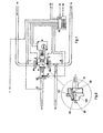
- the incoming liquid of the feed 14 passes through a connection 9A of a heat quantity meter 9 in a measuring nozzle ( Fig. 2 ), at which by a nozzle needle 100, the required flow is derived from the stroke of an actuator 8.
- the pressure difference of pressure transmitters 2 and 3 and the demand value of a temperature or pressure sensor 5 determine the proportionate admixture of the liquid from a connection 9B to an outlet 9C as a flow 17 of the consumer.
- the return 18 from the consumer passes as needed in the terminal 9B and the remainder as a difference in the return 15 of the feed.
- the pressure transmitters 2 and 3 provide a constant correction of the position of the nozzle needle 100 in the event that the pressure on the feed side is subject to fluctuations. In the event that a pressure limit on the side of the consumer is required, the pressure transducer 6 is provided.
- Temperature sensors 1 and 4 are used for heat measurement.
- the pressure transmitters 2 and 3 in conjunction with the actuator 8 define the effective pressure flow of the feed 14 via the nozzle constant. From the measured temperature difference and the measured flow, the heat consumption is calculated and stored in a database.
- the equipped with a processor controller 10 processes all signals of the temperatures (1, 4, 5, outside temperature sensor 7) and the pressures (2, 3, 6) for the position transmitter of the actuator. 8
- the control part consists of an annular part or a nozzle 101 with an internally formed conical bore. Inside the annular part 101 is a plunger or a needle 100 which is formed substantially cylindrical, but with a gradation 20 and finally a tapered portion 22nd
- control planes namely a control plane 21 and a second control plane 22 are defined and a calibrated orifice nozzle orifice 23.
- the needle part 100 can be adjusted with respect to the annular part 101, so that in this way the flow rate and the pressure can be adjusted as desired.
- the actuator 8 may be electrically, electronically, hydraulically or pneumatically.
- the positioner in the actuator can be realized inductively, digitally or by means of resistance.
- the actuation of the actuator can be a 3-point control or proportional or pneumatic.
Description
- Die Erfindung betrifft eine Vorrichtung zur Messung und Regelung der individuellen Verbrauchswerte einzelner Verbraucher von Flüssigkeiten als Wärmeträger in wärmetechnischen Anlagen, mit einem Vorlauf und einem Rücklauf von und zu einem Wärmelieferanten, einem Vorlauf und einem Rücklauf zu und von einem Verbraucher, einem Regelteil für die an den Verbraucher gelieferte Menge des Wärmeträgers sowie Messeinrichtungen für die Menge, den Druck und die Temperaturen des Wärmeträgers.
- Eine Vorrichtung der eingangs genannten Art ist aus der
US 5,153,823 A bekannt, welche ein sog. Drosselorgan verwendet. Gemäß einer Ausführung weist das Drosselorgan ein Gehäuse, das einen Strömungskanal für das Strömungsmedium umschließt, und eine Kreislochblende auf, die im Zuge des Strömungskanals quer zur Strömungsrichtung angeordnet ist. In die Öffnung der Kreislochblende taucht ein Verdrängungskörper ein, wodurch ein Ringspalt gebildet wird, der den wirksamen Querschnitt des Drosselorganes darstellt. Der Verdrängungskörper besteht aus einzelnen zylindrischen Abschnitten mit diskret abgestuften Außendurchmessern, um mehrere verschieden große Ringspalte zu erzeugen und dadurch das Drosselorgan mehrstufig schaltbar auszuführen. Neben anderen Größen wird auch der Druck durch einen externen Sensor erfasst, der als Differenzdrucksensor ausgeführt ist, dessen Komponenten gemäß einer bevorzugten Ausführung zumindest teilweise innerhalb des Verdrängungskörpers angeordnet sind. Bei einer modifizierten Ausführung ist im Inneren des Gehäuses eine konische Fläche ausgebildet, die als Sitz dient, gegen den in der Schließstellung ein am Verdrängungskörper ausgebildeter Teller mit einer ebenfalls konisch geformten Dichtfläche drückt, um in dieser Stelllung einen dichtenden Verschluss zu erzielen und ferner zu erreichen, dass bei geschlossenem Ventil der Differenzdruck am Differenzdrucksensor stets null ist. - Die
EP 03 096 643 A1 - Demgegenüber wird von der Erfindung vorgeschlagen eine Vorrichtung zur Messung und Regelung der individuellen Verbrauchswerte einzelner Verbraucher von Flüssigkeiten als Wärmeträger in wärmetechnischen Anlagen, mit einem Vorlauf und einem Rücklauf von und zu einem Wärmelieferanten, einem Vorlauf und einem Rücklauf zu und von einem Verbraucher, einem Regelteil für die an den Verbraucher gelieferte Menge des Wärmeträgers sowie Messeinrichtungen für die Menge, den Druck und die Temperaturen des Wärmeträgers, dadurch gekennzeichnet, dass der Regelteil mit der Messeinrichtung für die Menge des Wärmeträgers zu einem Gerät vereinigt ist, der Regelteil mit einer ringförmigen Düse mit einem im Wesentlichen konischen Durchgang und einem in der Düse verstellbaren Stößel ausgebildet ist, der Stößel zur Düse eichfähig so verstellbar ist, dass sowohl der Druck über eine Kante einer Abstufung am Stößel als auch die Menge des Wärmeträgers über eine Kante im konischen Durchgang der Düse einregelbar sind, der Stößel als längliche Nadel mit der Abstufung und einer kegeligen Spitze ausgebildet ist, der Regelteil im Inneren der mit dem Vorlauf vom Wärmelieferanten und dem Vorlauf zum Verbraucher verbundenen Leistungen der Messeinrichtung angeordnet ist und der Rücklauf vom Verbraucher sowohl mit dem Rücklauf zum Wärmelieferanten als auch mit dem Regelteil verbunden und die gesamte Anordnung derart getroffen ist, dass der Wärmeträger im Rücklauf vom Verbraucher je nach Bedarf in den Regelteil und der verbleibende Rest als Differenz in den Rücklauf zum Wärmelieferanten gelangt.
- Durch die Erfindung soll eine erhebliche bauliche Vereinfachung in den o.a. Anlagen erzielt werde, was bei einer Vorrichtung der vorangehend beschriebenen Art dadurch erreicht wird, dass der Regelteil mit der Messeinrichtung für die Menge des Energieträgers zu einem Gerät vereinigt ist, dass in einer ringförmigen Düse mit einem im wesentlichen konischen Durchgang ein eichfähig ausgebildeter und in der Düse eichfähig verstellbarer Stößel angeordnet ist, wobei je nach Position von Stößel und Düse sowohl der Druck über eine Kante am Stößel als auch die Menge des Energieträgers über eine Kante im konischen Durchgang der Düse eichfähig einregelbar sind.
- Die Erfindung geht von einer allgemein bekannten Wasserstrahlpumpe oder auch einem Dreiwegeventil aus, jedoch mit einer im Inneren veränderten Ausgestaltung, und zwar mit einer Messkammer und einer Messdüse, welche über zwei unterschiedliche Regelebenen verfügt. Ein Kragen einer Düsennadel regelt gemäß der Erfindung auf der ersten Ebene den Druck und gibt gleichzeitig einen gasdichten Abschluss. Die Düsennadel öffnet oder schließt mit der zweiten, genau kalibrierten Messöffnung der Düse den Durchfluss.
- Das eigentliche Messelement besteht aus Messdüse und Düsennadel und ist verschleißfrei. Die Genauigkeit der Messung übertrifft alle bekannten Messverfahren, die derzeit praktiziert werden. Darüber hinaus ist die Regelung der Temperatur und des Druckes sowie die Begrenzung von Temperatur, Druck und Durchfluss möglich. Diese Fähigkeiten werden dem Gerät durch eine elektronische Einheit verliehen, die Transmitter, Regler, Computer, Datenbank und Steuergerät umfasst. Der Transmitter wandelt die Messwerte des Drucks, der Temperatur in spezifische Größen um. Der Computerteil berechnet die Verhältnisse zwischen Temperaturen einerseits und Drücken andererseits. Der ermittelte Verbrauch und Durchfluss werden dauerhaft in der Datenbank generiert. Werte, welche eine Regelabweichung zu den eingestellten Sollwerten darstellen, werden an den Reglerteil übermittelt und als Regelabweichung an das Steuergerät in ein entsprechendes Signal umgewandelt, um das Stellglied zu verstellen. Die Messung mittels Düse und Düsennadel entspricht einer Messung mit einer veränderlichen Venturidüse und erbringt eine Messgenauigkeit über eine Messblende, welche Grundlage für die Eichung des verwendeten Durchflussmessers ist. Durch die Möglichkeit der Programmierung der Messeinheit mit spezifischen Werten und Eigenschaften der betreffenden Flüssigkeit sind Messfehler ausgeschlossen, wie sie in bekannten Verfahren zwangsläufig auftreten.
- Die Vorzüge der Erfindung bestehen darin, das keine beweglichen Teile erforderlich sind und ein Einsatz bei sehr hohen Drücken und Temperaturen möglich ist. Regelventile, Druckregler und Durchflussbegrenzer sind überflüssig. Unter Verwendung eines Diffusors werden elektrische Pumpen überflüssig, so dass elektrische Energie gespart wird. Die Anlagen werden übersichtlicher, bedienerfreundlicher und die Störungsanfälligkeit wird eliminiert.
- Die Erfindung wird nachstehend anhand der Zeichnung beispielsweise erläutert.
- Fig. 1
- zeigt ein Wärmeübergabesystem mit einem Regelteil gemäß der Erfindung.
- Fig. 2
- zeigt im vergrößerter Darstellung eine Querschnittsansicht des Regelteils gemäß der Erfindung.
- Die eintretende Flüssigkeit der Einspeisung 14 gelangt über einen Anschluss 9A eines Wärmemengenzählers 9 in eine Messdüse (
Fig. 2 ), an welcher durch eine Düsennadel 100 der erforderliche Durchfluss aus dem Hub eines Stellgliedes 8 hergeleitet wird. Die Druckdifferenz von Druckgebern 2 und 3 und der Bedarfswert eines Gebers für Temperatur 5 oder Druck 6 legen die anteilige Beimischung der Flüssigkeit von einem Anschluss 9B an einen Austritt 9C als Vorlauf 17 des Verbrauchers fest. Der Rücklauf 18 vom Verbraucher gelangt je nach Bedarf in den Anschluss 9B und der verbleibende Rest als Differenz in den Rücklauf 15 der Einspeisung. - Die Druckgeber 2 und 3 sorgen für eine ständige Korrektur der Lage der Düsennadel 100 für den Fall, dass der Druck auf der Einspeisungsseite Schwankungen unterworfen ist. Für den Fall, dass eine Druckbegrenzung auf der Seite des Verbrauchers verlangt wird, ist der Druckgeber 6 vorgesehen.
- Temperaturgeber 1 und 4 dienen der Wärmemessung. Die Druckgeber 2 und 3 in Verbindung mit dem Stellglied 8 definieren über die Düsenkonstante den effektiven Druckfluss der Einspeisung 14. Aus der gemessenen Temperaturdifferenz und dem gemessenen Durchfluss wird der Wärmeverbrauch errechnet und in einer Datenbank abgelegt.
- Der mit einem Prozessor ausgestattene Regler 10 verarbeitet alle Signale der Temperaturen (1, 4, 5, Außentemperaturfühler 7) und der Drücke (2, 3, 6) für den Stellungsgeber des Stellgliedes 8.
- Der Regelteil gemäß der Erfindung besteht aus einem ringförmigen Teil oder einer Düse 101 mit einer im Inneren ausgebildeten kegeligen Bohrung. Im Inneren des ringförmigen Teils 101 befindet sich ein Stößel oder eine Nadel 100, die im wesentlichen zylindrisch ausgebildet ist, allerdings mit einer Abstufung 20 und schließlich einem spitz zulaufenden Teil 22.
- Durch die Lage der Teile 100 und 101 in Bezug aufeinander werden zwei Regelebenen, nämlich eine Regelebene 21 und eine zweite Regelebene 22 festgelegt sowie eine kalibrierte Messblenden-Düsenöffnung 23.
- Der Nadelteil 100 kann in Bezug auf den ringförmigen Teil 101 verstellt werden, so dass auf diese Art und Weise die Durchflussmenge und der Druck in gewünschter Weise eingestellt werden kann.
- Am Regler 10 sind drei Ausgänge vorgesehen, und zwar Ausgang
- 1. für das Auslesen der Datenbank, der errechneten Verbrauchswerte sowie das Löschen überholter Verbrauchswerte aus einem früheren Zeitraumt: Ausgang 12,
- 2. für die Sollwert-Verstellung durch Telemetrie, Ausgang 16,
- 3. für das Auslesen der Datenbank und der errechneten Verbrauchswerte durch Telemeterie: Ausgang 11,
- 4. für die Datenkopplung über die Netzspeisung: Ausgang 13.
- Der Stellantrieb 8 kann elektrisch, elektronisch, hydraulisch oder pneumatisch ausgebildet sein. Der Stellungsgeber im Stellantrieb kann induktiv, digital oder mittels Widerstand realisiert werden. Die Ansteuerung des Stellantriebs kann eine 3-Punkt-Regelung oder proportional oder pneumatisch sein.
Claims (1)
- Vorrichtung zur Messung und Regelung der individuellen Verbrauchswerte einzelner Verbraucher von Flüssigkeiten als Wärmeträger in wärmetechnischen Anlagen, mit einem Vorlauf (14) und einem Rücklauf (15) von und zu einem Wärmelieferanten, einem Vorlauf (17) und einem Rücklauf (18) zu und von einem Verbraucher, einem Regelteil (9) für die an den Verbraucher gelieferte Menge des Wärmeträgers sowie Messeinrichtungen für die Menge, den Druck und die Temperaturen des Wärmeträgers,
dadurch gekennzeichnet, dass
der Regelteil (9) mit der Messeinrichtung für die Menge des Wärmeträgers zu einem Gerät vereinigt ist,
der Regelteil (9) mit einer ringförmigen Düse (101) mit einem im Wesentlichen konischen Durchgang (21) und einem in der Düse (101) verstellbaren Stößel (100) ausgebildet ist,
der Stößel (100) zur Düse (101) eichfähig so verstellbar ist, dass sowohl der Druck über eine Kante (20) einer Abstufung am Stößel (100) als auch die Menge des Wärmeträgers über eine Kante (23) im konischen Durchgang (21) der Düse (101) einregelbar sind,
der Stößel (100) als längliche Nadel mit der Abstufung und einer kegeligen Spitze (22) ausgebildet ist,
der Regelteil (9) im Inneren der mit dem Vorlauf (14) vom Wärmelieferanten und dem Vorlauf (17) zum Verbraucher verbundenen Leitungen der Messeinrichtung angeordnet ist und
der Rücklauf (18) vom Verbraucher sowohl mit dem Rücklauf (15) zum Wärmelieferanten als auch mit dem Regelteil (9) verbunden und die gesamte Anordnung derart getroffen ist, dass der Wärmeträger im Rücklauf (18) vom Verbraucher je nach Bedarf in den Regelteil (9) und der verbleibende Rest als Differenz in den Rücklauf (15) zum Wärmelieferanten gelangt.
Applications Claiming Priority (2)
| Application Number | Priority Date | Filing Date | Title |
|---|---|---|---|
| DE10058484 | 2000-11-24 | ||
| DE10058484A DE10058484A1 (de) | 2000-11-24 | 2000-11-24 | Vorrichtung für die Messung und Regelung der Verbrauchswerte von Wärmeübertragungsflüssigkeiten |
Publications (3)
| Publication Number | Publication Date |
|---|---|
| EP1211487A2 EP1211487A2 (de) | 2002-06-05 |
| EP1211487A3 EP1211487A3 (de) | 2002-07-24 |
| EP1211487B1 true EP1211487B1 (de) | 2010-03-10 |
Family
ID=7664584
Family Applications (1)
| Application Number | Title | Priority Date | Filing Date |
|---|---|---|---|
| EP01128027A Expired - Lifetime EP1211487B1 (de) | 2000-11-24 | 2001-11-26 | Vorrichtung für die Messung und Regelung der Verbrauchswerte von Energieträgerflüssigkeiten |
Country Status (4)
| Country | Link |
|---|---|
| EP (1) | EP1211487B1 (de) |
| AT (1) | ATE460648T1 (de) |
| DE (2) | DE10058484A1 (de) |
| DK (1) | DK1211487T3 (de) |
Cited By (1)
| Publication number | Priority date | Publication date | Assignee | Title |
|---|---|---|---|---|
| CN109340902A (zh) * | 2018-10-17 | 2019-02-15 | 余宝法 | 一种调节型水喷射泵供热平衡系统及其平衡方法 |
Families Citing this family (2)
| Publication number | Priority date | Publication date | Assignee | Title |
|---|---|---|---|---|
| ITMI20120727A1 (it) * | 2012-05-02 | 2013-11-03 | E D C S R L | Dispositivo di regolazione e misura di flusso di un fluido termovettore e relativo sistema di contabilizzazione di energia termica e di regolazione per un radiatore o calorifero |
| KR101407642B1 (ko) * | 2012-11-08 | 2014-06-13 | 한국에너지기술연구원 | 양방향 열량계 |
Family Cites Families (3)
| Publication number | Priority date | Publication date | Assignee | Title |
|---|---|---|---|---|
| US5153823A (en) * | 1989-04-03 | 1992-10-06 | Landis & Gyr Betriebs Ag | Device to measure and/or control flow-through and/or quantity of heat |
| AU2934700A (en) * | 1999-03-25 | 2000-10-16 | Technology Finance Corporation (Proprietary) Limited | Fluid flow control method and apparatus for filtration system |
| DE20009158U1 (de) * | 2000-05-20 | 2000-08-24 | Techem Service Ag | Vorrichtung zur Erfassung der Wärmeabgabe eines Heizkörpers und Regelung der Raumtemperatur |
-
2000
- 2000-11-24 DE DE10058484A patent/DE10058484A1/de not_active Withdrawn
-
2001
- 2001-11-26 DK DK01128027.8T patent/DK1211487T3/da active
- 2001-11-26 DE DE50115380T patent/DE50115380D1/de not_active Expired - Lifetime
- 2001-11-26 EP EP01128027A patent/EP1211487B1/de not_active Expired - Lifetime
- 2001-11-26 AT AT01128027T patent/ATE460648T1/de active
Cited By (1)
| Publication number | Priority date | Publication date | Assignee | Title |
|---|---|---|---|---|
| CN109340902A (zh) * | 2018-10-17 | 2019-02-15 | 余宝法 | 一种调节型水喷射泵供热平衡系统及其平衡方法 |
Also Published As
| Publication number | Publication date |
|---|---|
| DE10058484A1 (de) | 2002-05-29 |
| DK1211487T3 (da) | 2010-07-05 |
| DE50115380D1 (de) | 2010-04-22 |
| ATE460648T1 (de) | 2010-03-15 |
| EP1211487A3 (de) | 2002-07-24 |
| EP1211487A2 (de) | 2002-06-05 |
Similar Documents
| Publication | Publication Date | Title |
|---|---|---|
| DE2756178C2 (de) | ||
| DE60110836T2 (de) | Selbstzentrierende magnetanordnung zur verwendung in einem linearen wegmesser | |
| EP1084369B1 (de) | Regeleinrichtung für gasbrenner | |
| DE60128566T2 (de) | Durchflussregelung für ein prozessgas in der halbleiterfertigung | |
| DE10085498T5 (de) | Chemisch inerte Strömungssteuerung mit kontaminationsfreiem Gehäuse | |
| EP0946910B2 (de) | Strangregulierarmatur | |
| DE102008008427B3 (de) | Kalibriervorrichtung zum Kalibrieren eines Gasflussmessers | |
| EP1303717B1 (de) | Ventil | |
| EP1211487B1 (de) | Vorrichtung für die Messung und Regelung der Verbrauchswerte von Energieträgerflüssigkeiten | |
| DE3044540A1 (de) | Druckuebertrager | |
| DE4206875A1 (de) | Gasdruckregelsystem | |
| DE3220815C2 (de) | Druckregelvorrichtung für gasförmige und flüssige Strömungsmittel | |
| DE102008028189B4 (de) | Elektropneumatisches Ventil | |
| EP0565485A1 (de) | Verfahren und Vorrichtung zum Messen der Durchflussmenge eines Mediums und Anwendung des Verfahrens | |
| WO2020186279A1 (de) | Messsystem zur messung eines massendurchflusses, einer dichte, einer temperatur und/oder einer strömungsgeschwindigkeit | |
| DE19725376A1 (de) | Strangregulierarmatur | |
| EP3997424B1 (de) | Messsystem zur messung eines durchflusses | |
| DE102009060262A1 (de) | Verfahren und Anordnung zum Regeln einer Prozessfluidströmung und Stellungsregler | |
| EP0602629B1 (de) | Wasserarmatur, insbesondere Wassermischarmatur mit Durchflussmesseinrichtung | |
| EP0858565B1 (de) | Gaseinlassvorrichtung für eine beschichtungsanlage | |
| EP1447329A1 (de) | Verfahren und Vorrichtung zum Abfüllen eines Mediums | |
| DE10114996B4 (de) | Vorrichtung zur Messung von Druck- und/oder Temperatur in einem fluidführenden Mediumkanal | |
| DE4303483A1 (de) | Regler | |
| DE10062681C2 (de) | Flüssigkeitsventil für Heiz- und/oder Kühlanlagen | |
| AT521899B1 (de) | Messsystem und Verfahren zur Messung eines Massendurchflusses, einer Dichte, einer Temperatur oder einer Strömungsgeschwindigkeit |
Legal Events
| Date | Code | Title | Description |
|---|---|---|---|
| PUAI | Public reference made under article 153(3) epc to a published international application that has entered the european phase |
Free format text: ORIGINAL CODE: 0009012 |
|
| AK | Designated contracting states |
Kind code of ref document: A2 Designated state(s): AT BE CH CY DE DK ES FI FR GB GR IE IT LI LU MC NL PT SE TR |
|
| AX | Request for extension of the european patent |
Free format text: AL;LT;LV;MK;RO;SI |
|
| PUAL | Search report despatched |
Free format text: ORIGINAL CODE: 0009013 |
|
| AK | Designated contracting states |
Kind code of ref document: A3 Designated state(s): AT BE CH CY DE DK ES FI FR GB GR IE IT LI LU MC NL PT SE TR |
|
| AX | Request for extension of the european patent |
Free format text: AL;LT;LV;MK;RO;SI |
|
| RIC1 | Information provided on ipc code assigned before grant |
Free format text: 7G 01F 1/42 A, 7G 01K 17/16 B, 7G 05D 7/06 B |
|
| 17P | Request for examination filed |
Effective date: 20030116 |
|
| AKX | Designation fees paid |
Designated state(s): AT BE CH CY DE DK ES FI FR GB GR IE IT LI LU MC NL PT SE TR |
|
| 17Q | First examination report despatched |
Effective date: 20060301 |
|
| GRAP | Despatch of communication of intention to grant a patent |
Free format text: ORIGINAL CODE: EPIDOSNIGR1 |
|
| GRAS | Grant fee paid |
Free format text: ORIGINAL CODE: EPIDOSNIGR3 |
|
| GRAA | (expected) grant |
Free format text: ORIGINAL CODE: 0009210 |
|
| AK | Designated contracting states |
Kind code of ref document: B1 Designated state(s): AT BE CH CY DE DK ES FI FR GB GR IE IT LI LU MC NL PT SE TR |
|
| REG | Reference to a national code |
Ref country code: GB Ref legal event code: FG4D Free format text: NOT ENGLISH |
|
| REG | Reference to a national code |
Ref country code: CH Ref legal event code: EP |
|
| REG | Reference to a national code |
Ref country code: IE Ref legal event code: FG4D |
|
| REF | Corresponds to: |
Ref document number: 50115380 Country of ref document: DE Date of ref document: 20100422 Kind code of ref document: P |
|
| REG | Reference to a national code |
Ref country code: CH Ref legal event code: NV Representative=s name: PATENTANWAELTE SCHAAD, BALASS, MENZL & PARTNER AG |
|
| REG | Reference to a national code |
Ref country code: NL Ref legal event code: T3 |
|
| REG | Reference to a national code |
Ref country code: SE Ref legal event code: TRGR |
|
| REG | Reference to a national code |
Ref country code: DK Ref legal event code: T3 |
|
| REG | Reference to a national code |
Ref country code: IE Ref legal event code: FD4D |
|
| PG25 | Lapsed in a contracting state [announced via postgrant information from national office to epo] |
Ref country code: ES Free format text: LAPSE BECAUSE OF FAILURE TO SUBMIT A TRANSLATION OF THE DESCRIPTION OR TO PAY THE FEE WITHIN THE PRESCRIBED TIME-LIMIT Effective date: 20100621 Ref country code: CY Free format text: LAPSE BECAUSE OF FAILURE TO SUBMIT A TRANSLATION OF THE DESCRIPTION OR TO PAY THE FEE WITHIN THE PRESCRIBED TIME-LIMIT Effective date: 20100310 Ref country code: GR Free format text: LAPSE BECAUSE OF FAILURE TO SUBMIT A TRANSLATION OF THE DESCRIPTION OR TO PAY THE FEE WITHIN THE PRESCRIBED TIME-LIMIT Effective date: 20100611 |
|
| PLBE | No opposition filed within time limit |
Free format text: ORIGINAL CODE: 0009261 |
|
| STAA | Information on the status of an ep patent application or granted ep patent |
Free format text: STATUS: NO OPPOSITION FILED WITHIN TIME LIMIT |
|
| PG25 | Lapsed in a contracting state [announced via postgrant information from national office to epo] |
Ref country code: IE Free format text: LAPSE BECAUSE OF FAILURE TO SUBMIT A TRANSLATION OF THE DESCRIPTION OR TO PAY THE FEE WITHIN THE PRESCRIBED TIME-LIMIT Effective date: 20100310 Ref country code: PT Free format text: LAPSE BECAUSE OF FAILURE TO SUBMIT A TRANSLATION OF THE DESCRIPTION OR TO PAY THE FEE WITHIN THE PRESCRIBED TIME-LIMIT Effective date: 20100712 |
|
| 26N | No opposition filed |
Effective date: 20101213 |
|
| PG25 | Lapsed in a contracting state [announced via postgrant information from national office to epo] |
Ref country code: MC Free format text: LAPSE BECAUSE OF NON-PAYMENT OF DUE FEES Effective date: 20101130 |
|
| PG25 | Lapsed in a contracting state [announced via postgrant information from national office to epo] |
Ref country code: LU Free format text: LAPSE BECAUSE OF NON-PAYMENT OF DUE FEES Effective date: 20101126 |
|
| REG | Reference to a national code |
Ref country code: FR Ref legal event code: PLFP Year of fee payment: 15 |
|
| PGFP | Annual fee paid to national office [announced via postgrant information from national office to epo] |
Ref country code: CH Payment date: 20151123 Year of fee payment: 15 Ref country code: DE Payment date: 20151208 Year of fee payment: 15 Ref country code: GB Payment date: 20151123 Year of fee payment: 15 Ref country code: IT Payment date: 20151124 Year of fee payment: 15 Ref country code: FI Payment date: 20151120 Year of fee payment: 15 Ref country code: DK Payment date: 20151124 Year of fee payment: 15 |
|
| PGFP | Annual fee paid to national office [announced via postgrant information from national office to epo] |
Ref country code: FR Payment date: 20151124 Year of fee payment: 15 Ref country code: SE Payment date: 20151123 Year of fee payment: 15 Ref country code: BE Payment date: 20151124 Year of fee payment: 15 Ref country code: AT Payment date: 20151120 Year of fee payment: 15 Ref country code: NL Payment date: 20151124 Year of fee payment: 15 |
|
| PG25 | Lapsed in a contracting state [announced via postgrant information from national office to epo] |
Ref country code: BE Free format text: LAPSE BECAUSE OF NON-PAYMENT OF DUE FEES Effective date: 20161130 |
|
| REG | Reference to a national code |
Ref country code: DE Ref legal event code: R119 Ref document number: 50115380 Country of ref document: DE |
|
| REG | Reference to a national code |
Ref country code: DK Ref legal event code: EBP Effective date: 20161130 |
|
| REG | Reference to a national code |
Ref country code: CH Ref legal event code: PL |
|
| REG | Reference to a national code |
Ref country code: SE Ref legal event code: EUG |
|
| REG | Reference to a national code |
Ref country code: NL Ref legal event code: MM Effective date: 20161201 |
|
| REG | Reference to a national code |
Ref country code: AT Ref legal event code: MM01 Ref document number: 460648 Country of ref document: AT Kind code of ref document: T Effective date: 20161126 |
|
| GBPC | Gb: european patent ceased through non-payment of renewal fee |
Effective date: 20161126 |
|
| PG25 | Lapsed in a contracting state [announced via postgrant information from national office to epo] |
Ref country code: FI Free format text: LAPSE BECAUSE OF NON-PAYMENT OF DUE FEES Effective date: 20161126 Ref country code: LI Free format text: LAPSE BECAUSE OF NON-PAYMENT OF DUE FEES Effective date: 20161130 Ref country code: CH Free format text: LAPSE BECAUSE OF NON-PAYMENT OF DUE FEES Effective date: 20161130 |
|
| REG | Reference to a national code |
Ref country code: FR Ref legal event code: ST Effective date: 20170731 |
|
| PG25 | Lapsed in a contracting state [announced via postgrant information from national office to epo] |
Ref country code: AT Free format text: LAPSE BECAUSE OF NON-PAYMENT OF DUE FEES Effective date: 20161126 Ref country code: SE Free format text: LAPSE BECAUSE OF NON-PAYMENT OF DUE FEES Effective date: 20161127 |
|
| PG25 | Lapsed in a contracting state [announced via postgrant information from national office to epo] |
Ref country code: NL Free format text: LAPSE BECAUSE OF NON-PAYMENT OF DUE FEES Effective date: 20161201 |
|
| PG25 | Lapsed in a contracting state [announced via postgrant information from national office to epo] |
Ref country code: FR Free format text: LAPSE BECAUSE OF NON-PAYMENT OF DUE FEES Effective date: 20161130 Ref country code: IT Free format text: LAPSE BECAUSE OF NON-PAYMENT OF DUE FEES Effective date: 20161126 |
|
| PG25 | Lapsed in a contracting state [announced via postgrant information from national office to epo] |
Ref country code: DK Free format text: LAPSE BECAUSE OF NON-PAYMENT OF DUE FEES Effective date: 20161130 Ref country code: GB Free format text: LAPSE BECAUSE OF NON-PAYMENT OF DUE FEES Effective date: 20161126 Ref country code: DE Free format text: LAPSE BECAUSE OF NON-PAYMENT OF DUE FEES Effective date: 20170601 |
|
| PGFP | Annual fee paid to national office [announced via postgrant information from national office to epo] |
Ref country code: TR Payment date: 20151126 Year of fee payment: 15 |
|
| REG | Reference to a national code |
Ref country code: BE Ref legal event code: MM Effective date: 20161130 |
|
| PG25 | Lapsed in a contracting state [announced via postgrant information from national office to epo] |
Ref country code: TR Free format text: LAPSE BECAUSE OF NON-PAYMENT OF DUE FEES Effective date: 20161126 |